Table of Contents
Advertisement
Available languages
Available languages
Jumbo
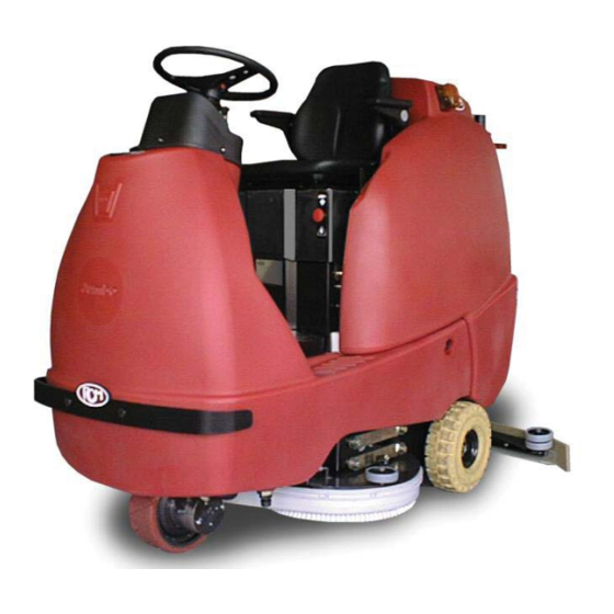
(33.JU.010) JUMBO 872 RN
(33.JU.011) JUMBO 962 N
(33.JU.012) JUMBO 1002 RN
ITA
MANUALE USO E MANUTENZIONE
GB
INSTRUCTION AND MAINTENANCE HANDBOOK
10/2012 Rev.00
RCM S.p.A. - 41041 CASINALBO (MO) Via Tiraboschi, 4
Tel. +39 059/51.53.11 - Telefax +39 059/51.07.83
Internet: http://www.rcm.it E-mail: inforcm@rcm.it
Advertisement
Table of Contents
Troubleshooting

Subscribe to Our Youtube Channel
Related Manuals for RCm Jumbo Series


Summary of Contents for RCm Jumbo Series
- Page 1 (33.JU.010) JUMBO 872 RN (33.JU.011) JUMBO 962 N (33.JU.012) JUMBO 1002 RN MANUALE USO E MANUTENZIONE INSTRUCTION AND MAINTENANCE HANDBOOK 10/2012 Rev.00 RCM S.p.A. - 41041 CASINALBO (MO) Via Tiraboschi, 4 Tel. +39 059/51.53.11 - Telefax +39 059/51.07.83 Internet: http://www.rcm.it E-mail: inforcm@rcm.it...
- Page 3 MANUALE USO E MANUTENZIONE INSTRUCTION AND MAINTENANCE HANDBOOK...
-
Page 4: Informazioni Preliminari
INFORMAZIONI PRELIMINARI I seguenti simboli hanno la funzione di attirare l’attenzione del lettore/utilizzatore ai fi ni di un uso corretto e sicuro della macchina, più precisamente hanno il seguente signifi cato: Attenzione: Evidenzia norme comportamentali da rispettare onde evitare danni alla macchina e la nascita di situazioni pericolose. -
Page 5: Preliminary Information
PRELIMINARY INFORMATION The symbols below are intended to attract the reader/user’s attention, in order to ensure proper, safe use of the machine. Their precise meanings are: Warning: Highlights procedures which must be followed in order to prevent damage to the machine and the generation of hazardous situations. -
Page 6: Table Of Contents
INDICE ARGOMENTI PAG. INFORMAZIONI PRELIMINARI ........................4 GENERALITÀ ..............................8 CARATTERISTICHE TECNICHE ........................10-12-14-16 COMANDI ................................18 DESCRIZIONE COMANDI ..........................20 NORME DI SICUREZZA GENERALI ......................24 MOVIMENTAZIONE MACCHINA ........................26 INDICAZIONI PER DISIMBALLARE LA MACCHINA ..................26 MOVIMENTAZIONE MACCHINA DISIMBALLATA ..................26 USO DELLA LAVASCIUGA ..........................28 • Norme per la messa in funzione della lavasciuga ..................28 NORME DA SEGUIRE DURANTE IL FUNZIONAMENTO ................30 NORME PER LA MANUTENZIONE ........................30 LAVAGGIO ..............................32... - Page 7 TABLE OF CONTENTS PAGE PRELIMINARY INFORMATION ........................5 GENERALITIES ...............................9 TECHNICAL DATA ............................11-13-15-17 CONTROLS ..............................19 DESCRIPTION OF CONTROLS ........................21 GENERAL SAFETY REGULATIONS ......................25 HANDLING THE MACHINE IN ITS PACKAGING ...................27 UNPACKING THE MACHINE ..........................27 HANDLING THE MACHINE AFTER UNPACKING ..................27 USING THE SCRUBBER/DRIER ........................29 •...
-
Page 8: Generalità
GENERALITÁ Dati per l’identifi cazione della lavasciuga FIG.1 TARGHETTA RIASSUNTIVA RICHIESTE DI INTERVENTO Le eventuali richieste di intervento devono essere fatte dopo una attenta analisi degli inconvenienti e delle loro cause ed è necessario riferire all’incaricato all’atto della chiamata: · Numero di matricola ·... -
Page 9: Generalities
GENERALITIES Data for Scrubber-Drier FIG.1 MACHINE TYPE LABEL CALLING IN THE AFTER-SALES SERVICE Before calling in the after-sales service, make a careful analysis of the problems and their causes When calling, please state: · Serial number · Detail of faults noted ·... -
Page 10: Caratteristiche Tecniche
CARATTERISTICHE TECNICHE Modelli : Jumbo 872RN Jumbo 962N Jumbo 1002RN Prestazioni Massima capacità oraria di pulizia m²/h 4300 4750 5000 Larghezza di lavaggio 1000 Larghezza di asciugatura 1100 1100 1100 Velocità max. di trasferimento km/h Velocità max. in retromarcia km/h Velocità... -
Page 11: Technical Data
TECHNICAL DATA Models : Jumbo 872RN Jumbo 962N Jumbo 1002RN Performances Max. cleaning capacity m²/h 4300 4750 5000 Scrub path 1000 Larghezza di asciugatura 1100 1100 1100 Max. transfer speed km/h Max. reverse speed km/h Max. working speed km/h Max. working gradient Max. - Page 12 CARATTERISTICHE TECNICHE Modelli : Jumbo 872RN Jumbo 962N Jumbo 1002RN Serbatoi Acqua pulita / soluzione Acqua sporca / recupero Depressione mm/H O 1600 1600 1600 Sterzatura meccanica su meccanica su meccanica su Sterzatura mediante volante tipo ruota anteriore ruota anteriore ruota anteriore Minimo spazio per inversione a “U”...
- Page 13 TECHNICAL DATA Models : Jumbo 872RN Jumbo 962N Jumbo 1002RN Tanks Solution tank (clean water) Recovery tank (dirt water) Vacuum-Operated mm/H O 1600 1600 1600 Steering mechanical on mechanical on mechanical on Steering wheel type front wheel front wheel front wheel Minimum “U”-turn space 2250 2250...
- Page 14 CARATTERISTICHE TECNICHE Modelli : Jumbo 872RN Jumbo 962N Jumbo 1002RN Dimensioni della macchina (tergipavimento escluso) Lunghezza (A) 1785 1785 1785 Larghezza (B) 1110 Altezza (C) 1580 1580 1580 FIG.2 Pesi Peso della macchina a vuoto Peso della macchina a vuoto con batteria Peso in assetto di lavoro escluso operatore 1007 1000...
- Page 15 TECHNICAL DATA Models : Jumbo 872RN Jumbo 962N Jumbo 1002RN Machine dimension (without machine) Lenght (A) 1785 1785 1785 Width (B) 1110 Height (C) 1580 1580 1580 FIG.2 Weight Machine weight Machine weight with battery Machine weight without operator 1007 1000 Instruments Solution low level indicator light (orange)
- Page 16 CARATTERISTICHE TECNICHE Modelli : Jumbo 872RN Jumbo 962N Jumbo 1002RN Accessori in dotazione Motori elettrici: trazione / aspirazione / rotazione spazzole Freno di servizio Freno di stazionamento Spazzola a rulli in PPL Spazzole a disco in PPL Tergipavimento Lampeggianti di emergenza Comando sollevamento spazzole Accessori a richiesta Dischi abrasivi...
- Page 17 TECHNICAL DATA Models : Jumbo 872RN Jumbo 962N Jumbo 1002RN Standard equipment Electric motors: Drive / Suction / Brush rotation Service brake Parking brake PPL Roll-brush PPL Disc-brush Squeegee Emergency blinker Lifting brush control Optionals Abrasive discs Detergent doser H2O lance kit Batteria corazzata Battery charger Polyurethane rear wheels...
-
Page 18: Comandi
COMANDI (FIG.3) 1) POTENZIOMETRO PRECARICO BASAMENTO SPAZZOLE 2) LEVA FRENO DI STAZIONAMENTO 3) PEDALE ACCELLERATORE E RETROMARCIA 4) PEDALE FRENO 5) LEVA APERTURA / CHIUSURA RUBINETTO SOLUZIONE 6) PULSANTE COMANDO ASPIRAZIONE 7) INTERRUTTORE GENERALE A CHIAVE 8) SPIA (VERDE) APERTURA SOLUZIONE 9) AVVISATORE ACUSTICO 10) DISPLAY E PULSANTE FUNZIONI 11) -... -
Page 19: Controls
CONTROLS (FIG.3) BRUSH SUPPORT PRESSURE TRIMMER PARKING BRAKE LEVER ACCELLERATOR AND REVERSE PEDAL BRAKE PEDAL SOLUTION TAP ON/OFF LEVER SUCTION CONTROL BUTTON STARTING KEY SWITCH SOLUTION ON INDICATOR LIGHT (GREEN) HORN DISPLAY AND FUNCTION SWITCH SPEED SWITCH BRUSH CONTROL BUTTON SOLUTION TANK CAP EMERGENCY STOP BUTTON FORWARD AND REVERSE TRAVEL JOYSTICK... -
Page 20: Descrizione Comandi
DESCRIZIONE COMANDI (FIG.3) 1 ) P O T E N Z I O M E N T R O P R E C A R I C O BASAMENTO SPAZZOLE. Serve per regolare la pressione delle spazzole sul pavimento. la rotazione del potenziomentro in senso orario incrementa la pressione complessiva esercitata sul pavimento. -
Page 21: Description Of Controls
DESCRIPTION OF CONTROLS (FIG.3) 1) BRUSH SUPPORT PRESSURE TRIMMER Used to adjust the pressure the brushes apply to the fl oor. Turn clockwise to increase the total pressure applied to the fl oor. PARKING BRAKE LEVER Used to lock the brake pedal in and release it from the parking position. ACCELERATOR AND REVERSE PEDAL Controls the scrubber/drier’s speed in forward or reverse travel. - Page 22 11) - 12) COMMUTATORE VELOCITÁ. Serve per impostare il tipo di velocità da utilizzare in fase di trasferimento o in lavoro. Commutare sul simbolo “tartaruga” per impostare la lavasciuga ad una velocità bassa per una pulizia accurata. Commutare sul simbolo “lepre” per impostare la lavapavimenti ad una velocità...
- Page 23 11) - 12) SPEED SWITCH Used to set the type of speed to be used during travel or work. Turn to the “tortoise” symbol to set the machine at a low speed for thorough cleaning. Turn to the “hare” symbol to set the machine at a high speed for travel between jobs. Turn to between the “tortoise and hare”...
-
Page 24: Norme Di Sicurezza Generali
NORME DI SICUREZZA GENERALI La macchina descritta nel presente manuale è stata costruita in conformità alla Direttiva Comunitaria sulle macchine 2006/42/CE (Direttiva Macchine).È obbligo del responsabile della gestione della macchina atte- nersi alle direttive comunitarie e alle leggi nazionali vigenti, nei riguardi dell’ambiente di lavoro, ai fi ni della sicurezza e della salute degli operatori. -
Page 25: General Safety Regulations
GENERAL SAFETY REGULATIONS The machine described in this manual has been constructed in accordance with the EC Directive on machines no. 2006/42/CE (Machinery Directive). The person in charge of the machine is responsible for complying with EEC directives and local regulations with regard to the working environment to ensure the health and safety of operatives. -
Page 26: Movimentazione Macchina
MOVIMENTAZIONE MACCHINA IMBALLATA La macchina giunge imballata su pallet. Il peso e le dimensioni sono riportate nelle CARATTERISTICHE TECNICHE. Le forche del carrello o del transpallet devono essere posizionate in modo che il centro dell’imballo sia circa al centro delle forche stesse. Il collo deve essere movimentato con estrema attenzione, evitando urti e di alzarlo ad altezze considerevoli. -
Page 27: Handling The Machine In Its Packaging
HANDLING THE MACHINE IN ITS PACKAGING The machine is delivered packed on a pallet. The weight and dimensions are provided in the Technical Data. The forks of the lift-truck or pallet trolley must be positioned so that the centre of the machine is halfway between them. -
Page 28: Uso Della Lavasciuga
USO DELLA LAVASCIUGA Precauzioni necessarie 1. La lavasciuga deve essere usata solo da persone competenti e responsabili. 2. Quando si lascia la lavasciugai incustodita, occorre togliere la chiave 7 (fi g.3) ed arrestarla bloccando il freno di stazionamento (vedi capitolo FRENI). 3. -
Page 29: Using The Scrubber/Drier
USING THE SCRUBBER/DRIER Necessary precautions The scrubber/drier must only be used by competent, responsible persons. When the scrubber/drier is left unattended, remove the key 7 (fi g. 3) and stop it moving by engaging and locking the parking brake (see BRAKES). When the fl... -
Page 30: Norme Da Seguire Durante Il Funzionamento
NORME DA SEGUIRE DURANTE IL FUNZIONAMENTO · Non lasciare avvicinare alla macchina persone estranee al lavoro. · L’uso della macchina é consentito solo agli operatori autorizzati dal responsabile della gestione della macchina e a conoscenza del contenuto del presente manuale. ·... -
Page 31: Regulation To Be Complied With During Operation
REGULATIONS TO BE COMPLIED WITH DURING OPERATION · Never allow outsiders to approach the machine. · The machine must only be used by operators authorized by the person in charge of the machine, familiar with the contents of this manual. ·... -
Page 32: Lavaggio
LAVAGGIO L’operazione di lavaggio con la vostra lavasciuga risulta essere molto semplice, sarà poi l’esperienza che vi aiuterà a migliorare il lavoro agevolandovi nella scelta del tipo di spazzole, del tipo di detergente, nella valutazione della necessità di una doppia azione di pulitura, ecc. In caso di pavimento molto sporco o molto tenace, sarà... -
Page 33: Washing
WASHING Washing using your scrubber/drier is very simple. Experience will enable you to improve results by choo- sing the most suitable type of brush and detergent, by deciding when to use the two phase procedure, etc. If the fl oor is very dirty or in case of very tough dirt, the two phase procedure should be used. A fi rst pass is made on a few tens of square metres of fl... -
Page 34: Carico E Scarico Acqua
Carico e scarico acqua (fi g.4) Prima di ogni lavaggio, riempire il serbatoio soluzione con la giusta quantità di acqua e detergente aprendo il bocchettone 14 (fi g. 3). Il serbatoio é costruito in polietilene, inattacabile da acidi e basi nonché dalla maggior parte dei solventi. Al termine del lavaggio scaricare l’acqua sporca dal serbatoio di recupero tramite il tubo 2 aprendo il tappo 3 Pulire perfettamente, almeno una volta alla settimana il serbatoio di recupero, aprendo il coperchio 1 to- gliendo il motore aspirazione, poi il suo fi... -
Page 35: Adding And Draining Water
Adding and draining water (fi g.4) Before each cleaning operation, open the cap 14 (fi g. 3) and fi ll the solution tank with the right amount of water and detergent. The tank is in polyethylene and is resistant to acids, bases and most solvents. After cleaning, drain the dirty water from the recovery tank using the hose 2, by opening the cap 3. -
Page 36: Piani Di Manutenzione
PIANI DI MANUTENZIONE (FIG.5) ATTENZIONE! PRIMA DI PROCEDERE ALLA SOSTITU- ZIONE DELLE SPAZZOLE, TOGLIERE LA CHIAVE DAL QUADRO DI AVVIAMENTO, EVITANDO COSÌ L’ACCENSIONE ACCI- DENTALE DI QUALCHE MOTORE. Sostituzione spazzole a disco Il basamento spazzole è dotato di due aperture d’ispezione (A, B) utilizzate per controllare lo stato di usura delle spazzole e la sostituzione delle stesse se necessario, procedere come segue:... -
Page 37: Maintenance
MAINTENANCE (FIG.5) CAUTION! BEFORE REPLACING THE BRUSHES, REMOVE THE KEY FROM THE STARTER PANEL, TO ENSURE THAT NO MOTOR CAN BE STARTED ACCIDENTALLY Replacing the disc brushes The brushes support has two inspection slots (A, B) used for check or replace the brush if necessary: - open the cover and insert the hand trough the slot (A &... -
Page 38: Sostituzione Spazzole A Rullo
Sostituzione spazzole a rullo (fi g.6) procedere nel seguente modo: Tirare verso l’alto la levetta laterale sinistra 1 del basamento spazzole per sganciare il fl ap 2. Ruotare il supporto spazzola 3 in senso orario fi no a fi ne asola. Sfi... -
Page 39: Replacing The Roller Brushes
Replacing the roll brushes (fi g.6) Proceed as follows: 1) Pull up left side lever 1 in order to unlock the fl ap 2. 2) Turn the brush mount 3 clockwise to the end of its slot. 3) Remove the mount 3 from the support and remove the brush 4 on left side as shown in the photo. 4) Fit the new brush by repeating the operations in reverse order. -
Page 40: Preparazione Della Macchina
PREPARAZIONE DELLA MACCHINA (FIG.7) Montaggio e regolazione del tergipavimento Per esigenze d’imballaggio il tergipavimento potrebbe venir fornito smontato dalla macchina e dovrà essere applicato alla piastra di traino sulla lavapavimenti. Per il montaggio del tergipavimento procedere nel seguente modo: · Sollevare la piastra porta tergipavimento. -
Page 41: Preparing The Machine
PREPARING THE MACHINE (FIG.7) Fitting and adjusting the squeegee To suit packaging requirements, the squeegee may be supplied dismantled from the machine, in which case it must be fi tted on the drive plate on the scrubber-drier. To fi t the squeegee, proceed as follows: ·... -
Page 42: Lame Tergipavimento
LAME TERGIPAVIMENTO (FIG.8) La funzione delle lame é quella di trattenere l’acqua usata per il lavaggio, pertanto occorre conservarle sempre perfettamente funzionanti e sostituirle in caso di rottura o usura. Sostituzione delle lame ATTENZIONE! QUANDO LO SPIGOLO DI CONTATTO SUL PAVIMENTO RISULTA CONSUMATO, BISOGNA SOSTITUIRE O RUOTARE LE LAME IN GOMMA DEL TERGIPAVIMENTO. -
Page 43: Squeegee Rubber Blades
SQUEEGEE RUBBER BLADES (FIG.8) The blades are fi tted to trap the water used for washing; they must therefore always be kept in perfect wor- king order and replaced in case of breakage or wear. Replacing the blades CAUTION! WHEN THE EDGE IN CONTACT WITH THE FLOOR SUFFERS ABRASION, THE SQUE- EGEE BLADES MUST BE REPLACED. -
Page 44: Sistema Di Avanzamento
LA LAVASCIUGA HA LA TERZA VELOCITÀ UTILIZZATA SOLO PER IL TRAFERIMEN- TO E NON PER IL LAVORO. IN CASO DI AVARIA ALL’IMPIANTO ELETTRICO, NON APRIRE, NON DISCONNET- TERE LA CENTRALINA ELETTRONICA E/O I RELATIVI COMPONENTI. PER QUALSIASI MANUTENZIONE, REVISIONE O RIPARAZIONE CONTATTARE L’ASSISTENZA RCM. -
Page 45: Travel System
THE SCRUBBER-DRIER HAVE THE THIRD SPEED USED ONLY FOR TRANSFER BUT NOT TO WORK. IN CASE OF FAILURE OF THE ELECTRIC SYSTEM DO NOT OPEN, DO NOT DISCONNECT THE ELECTRONIC CONTROL UNIT AND/OR ITS COMPONENTS. FOR ANY MAINTENANCE, REVISION OR REPAIR, CONTACT THE RCM AUTHORISED SERVICE STAFF. -
Page 46: Sterzo
STERZO (FIG.10) Lo sterzo é azionato da una catena 1, che trasmette il moto dal pignone di rinvio 2 alla corona 3 sulla ruota anteriore. Per registrare il gioco che si puó creare sul volante guida, spostare il supporto del pignone agendo sui dadi 4. -
Page 47: Steering System
STEERING SYSTEM (FIG.10) The steering system is operated by a chain 1 which transmits the motion from the drive sprocket 2 to the driven sprocket 3 on the front wheel. To adjust any backlash which may have arisen on the steering wheel, move the drive sprocket support using the nuts 4. -
Page 48: Freni
FRENI (FIG.11) I freni servono per arrestare la lavasciuga in movimento e per tenerla ferma su superfi ci inclinate. La frenatura agisce sulle ruote posteriori tramite ganasce 2. Il comando freno 1 é di tipo meccanico. Per bloccare la macchina in posizione di stazionamento, agire nel seguente modo: A) Premere a fondo il pedale 3. -
Page 49: Brakes
BRAKES (FIG.11) The brakes are used to stop the scrubber/drier when in motion and to keep it stationary on inclined surfaces. The braking system acts on the rear wheels by means of shoes 2. The brake is operated by a mechanical system 1. To lock the machine in the parking position, proceed as below: A) Push to bottom the pedal 3. -
Page 50: Motore Aspirazione
MOTORE ASPIRAZIONE (FIG.12) Serve ad aspirare l’acqua raccolta dal tergipavimento. Il motore aspirazione 1 aspira tramite l’azionamento del pulsante 6 (fi g. 3), esso deve essere controllato giornalmente e all’ occorenza lavare il sottostante fi ltro 2. Per il controllo del motore aspirazione e per la pulizia del fi ltro operare nel seguente modo: ·... -
Page 51: Suction Motor
SUCTION MOTOR (FIG.12) This sucks up the water collected by the squeegee. The suction motor 1 is operated by means of the button 6 (fi g. 3); it must be checked daily, washing the fi lter underneath 2 if necessary. To check the suction motors and clean the fi... -
Page 52: Batteria
BATTERIA Controllo dello stato di carica della batteria. Poiché é acquisito che intercorre una relazione diretta tra il peso specifi co dell’elettrolito e lo stato di carica della batteria, si assume la misurazione del peso specifi co dell’elettrolito come effi cace e corretto controllo dello stato di carica della batteria. -
Page 53: Batteries
BATTERIES Check the battery charge condition Since the specifi c weight of the electrolyte is proportional to the battery’s charge condition, measuring the specifi c weight of the electrolyte is an effective, accurate way of checking the charge of the battery. When the battery is charged and in normal conditions, with the electrolyte at the correct level, its density will be about 1.260 (30°... -
Page 54: Installazione Batteria
INSTALLAZIONE BATTERIA (FIG.13) Per sostituire e/o montare la batteria procedere nel sguente modo: 1) Rimuovere sedile 1 dal supporto 2. 2) Sollevare il supporto 2. 3) Ribaltare il serbaboio di recupero 3 fi no ad appoggiarlo sul suo supporto 4. ATTENZIONE! SE SI DEVE SOLO CONTROLLARE LA BATTERIA ESEGUIRE LE STESSE... -
Page 55: Installing The Batteries
INSTALLING THE BATTERIES (FIG.13) To replace or mounting the battery proceed as follows: Remove seat 1 fromits support 2 Lift support 2 Turn over the recovery tank 3 and set it against the support 4. CAUTION! IF THE BATTERY MUST BE CHECKED, EXECUTE THE SAME OPERATIONS AS DESCRIBED IN THE POINTS 2)3) WITHOUT REMOVE SEAT 1. -
Page 56: Centralina Elettronica
CENTRALINA ELETTRONICA (FIG.14) La lavasciuga è dotata di una centralina elettronica 1 per il controllo dell’avanzamento. Questo tipo di apparecchiatura prevede anche la funzione di diagnostica degli eventuali problemi che do- vessero presentarsi. L’anomalia o il guasto verrà segnalato sul display. 2C00... -
Page 57: Descrizione Allarmi
DESCRIZIONE ALLARMI (FIG.14) ATTENZIONE! SE DOPO AVER RIPRISTINATO L’ANOMALIA O IL GUASTO NON DOVESSE SCOMPARIRE L’ALLARME VISUALIZZATO SUL DISPLAY, PROVARE A SPEGNERE E RIAVVIARE LA MACCHINA. CODICE ERRORE DESCRIZIONE DEL PROBLEMA AZIONE CORRETTIVA DA INTRAPRENDERE 0003 Provate a disconnettere le batterie, aspettate 30 0100 Individuato un possibile errore sulla scheda. - Page 58 CODICE ERRORE DESCRIZIONE DEL PROBLEMA AZIONE CORRETTIVA DA INTRAPRENDERE L’attuatore del piatto spazzole (ausiliario 1) è consi- Controllate lo stato delle connessioni dell’attuatore. 1412 derato in cortocircuito con il connettore 0V. Controllate eventuali cortocircuiti lungo il cablaggio. L’attuatore dello squeegee (ausiliario 2) è considerato Controllate lo stato delle connessioni dell’attuatore.
- Page 59 Blocco di emergenza attivato. Controllate i cavi al pulsante di emergenza. 7901 Il pulsante di sicurezza operatore è stato attivato. Controllate lo stato dei cavi al pulsante di sicurezza. RCM. TTENZIONE ER EVENTUALI CODICI ERRORE NON RIPORTATI IN TABELLA ONTATTARE IL ERVIZIO...
-
Page 60: Electronic Control Unit
ELECTRONIC CONTROL UNIT (FIG.14) The scrubber/drier is equipped with an electronic control unit 1 for control of its travel drive function. This type of equipment also includes diagnostics of any problems which may occur. The anomaly or failu- re is indicated on the display. -
Page 61: Description Of Alarms
DESCRIPTION OF ALARMS (FIG.14) WARNING! AFTER YOU HAVE REPAIRED THE FAILURE OR BREAKDOWN THE DISPLAY SHOWS THE SAME ALARM, TRY TO SWITCH OFF THE MACHINE AND RESTART IT. ERROR CODE PROBLEM DESCRIPTION CORRECTIVE ACTION 0003 Try disconnecting the batteries, wait for 30 seconds, 0100 A controller error has been detected. - Page 62 ERROR CODE PROBLEM DESCRIPTION CORRECTIVE ACTION The brush deck actuator, auxiliary 1, has been de- Check for contamination on the actuator connections. 1412 tected as being shorted to 0V. Check for a short circuit in the wiring harness. The squeegee actuator, auxiliary 2 has been de- Check for contamination on the actuator connections.
- Page 63 7900 Emergency Stop input has been activated. Check wiring to the E-Stop switch. 7901 Belly button has been activated. Check wiring to the belly button switch. AUTION ONTACT RCM SERVICE FOR ANY ERROR CODES NOT LISTED IN THE TABLE...
-
Page 64: Schema Impianto Elettrico
IMPIANTO ELETTRICO - LINEA CRUSCOTTO (FIG.15) ELECTRIC SYSTEM - DASHBOARD LINE... - Page 65 LEGENDA LINEA DASHBOARD LINE KEY CRUSCOTTO Spia elettrovalvola H2O H2O electrovalve warning light Potenziometro pressione spazzole Brushes pressure trimmer Interruttore avviamento Starting switch Claxon Horn Interruttore aspirazione Vacuum switch Pulsante arresto d’emergenza Emergency stop button Commutatore velocità Drive speed switch Interruttore spazzola Brush control switch Interruttore spazzola...
- Page 66 IMPIANTO ELETTRICO - LINEA CENTRALE CRUSCOTTO (FIG.15A) ELECTRIC SYSTEM - DASHBOARD MAIN LINE...
- Page 67 LEGENDA LINEA DASHBOARD MAIN LINE CENTRALE CRUSCOTTO Galleggiante H2O H2O Float Micro valvola H2O H2O valve microswitch M BR Motore spazzola M BR Brush motor M BR1 Motore spazzola M BR1 Brush motor P BRUSH Centralina spazzola P BRUSH Brush control unit P BRUSH Centralina spazzola P BRUSH Brush control unit Connettore LCD...
- Page 68 IMPIANTO ELETTRICO - LINEA POSTERIORE (FIG.15B) ELECTRIC SYSTEM - REAR LINE...
- Page 69 LEGENDA LINEA REAR LINE KEY POSTERIORE Centralina Electronic control unit Micro sedile Seat microswitch Micro sedile Float microswitch Luce d’emergenza Emergency light Buzzer retromarcia Reverse drive buzzer Motore (ventola) aspirazione Vacuum fan motor Vacum Centralina Vacum Electronic control X1.s Connettore linea centrale cruscotto X1.s Dashboard main line connector Legenda colori...
-
Page 70: Electric System
IMPIANTO ELETTRICO - LINEA ATTUATORI (PEDANA) (FIG.15C) ELECTRIC SYSTEM - ACTUATORS LINE (BOARD) - Page 71 LEGENDA LINEA ACTUATORS LINE KEY ATTUATORI Centralina Electronic control unit Fine corsa attuatore spazzole Brushes actuator limit switch Fine corsa attuatore squeegee Squeegee actuator limit switch Claxon Horn Attuatore spazzole Brushes actuator Attuatore squeegee Squeegee actuator Legenda colori Wiring colors Azzurro Light Blue Bianco...
-
Page 72: Fusibili E Led
FUSIBILI (FIG.16) FUSIBILE GENERALE 150A... -
Page 73: Fuses And Leds
FUSES (FIG.16) 150A MASTER FUSE... -
Page 74: Operazioni Periodiche Di Controllo Emanutenzione E Controlli Di Sicurezza
OPERAZIONI PERIODICHE DI CONTROLLO E MANUTENZIONE E CONTROLLI DI SICUREZZA 1) la lavasciuga deve essere ispezionata da un tecnico specializzato che controlli le condizioni di sicu- rezza della macchina o la presenza di eventuali danni o difetti nei seguenti casi: •... -
Page 75: Periodic Maintenance And Safety Checks
ROUTINE CONTROL AND MAINTENANCE OPERATIONS AND SAFETY CHECKS 1) The scrubber must be inspected by a specialist technician who checks its safety or for any damage or defects in the following cases: • before it is put into operation • after modifi... -
Page 76: Ricerca Dei Guasti
. Prima di sostituire il fusibile contattare Fusibile generale bruciato. La macchina non si avvia. il servizio assistenza RCM. Microinterruttore sotto il sedile è rotto. Sostituire microinterruttore. Disinserire il pulsante e ripetere la pro- cedura di avviamento. (vedi USO DELLA Pulsante arresto d’emergenza inserito. - Page 77 L’attuatore non riceve corrente. Controllare. Il gruppo spazzola non si alza o non si Motore attuatore rotto. Sostituire. abbassa. Problema sulla centralina. Contattare l’assistenza RCM. L’attuatore non riceve corrente. Controllare. Il tergipavimento non si alza o non si Motore attuatore rotto. Sostituire. abbassa.
-
Page 78: Troubleshooting
The battery fl at. display shows the problem. Before replace the fuse, contact the Main fuse blown. RCM Authorized service staff. The machine does not start. Microswitch under seat faulty. Replace the microswitch. Release the button and repeat the start- up procedure (see USING THE SCRUB- Emergency stop button pressed. -
Page 79: Troubleshooting
The brushes system does not lift and The actuator motor damaged. Replace. does not low. Problem on the electronic unit. Contact the RCM Authorized service staff. The actuator does not receve current. Check. The squeegee does not lift and does not The actuator motor damaged. -
Page 80: Informazioni Di Sicurezza
INFORMAZIONI DI SICUREZZA 1) Pulizia: Quando si effettua la pulizia o il lavaggio della macchina i detergenti aggressivi, acidi, ecc. devono essere usati con cautela. Attenersi alle istruzioni del produttore dei detergenti, e, nel caso, usare indumenti protettivi (tute, guanti, occhiali, ecc.). Vedi direttive CEE sull’argomento 2) Atmosfera esplosiva: La macchina non è... -
Page 81: Safety Information
SAFETY INFORMATION 1) Cleaning: When cleaning and washing the machine, take care when using aggressive detergents, acids, etc. Follow the instructions provided by the detergent producer, and wear protective clothing if appropriate (e.g. overalls, gloves, goggles, etc. - see EEC directives on this subject). 2) Explosive atmosphere: The machine is not constructed to work in environments where there is a risk that there might be explosive gases, dusts or vapours, and so its use in an explosive atmosphere is FORBIDDEN.
Need help?
Do you have a question about the Jumbo Series and is the answer not in the manual?
Questions and answers