Sign In
Upload
Download
Table of Contents
Contents
Add to my manuals
Delete from my manuals
Share
URL of this page:
HTML Link:
Bookmark this page
Add
Manual will be automatically added to "My Manuals"
Print this page
×
Bookmark added
×
Added to my manuals
Manuals
Brands
MSI Manuals
Server
MS-S322
User manual
MSI MS-S322 User Manual
Hide thumbs
Also See for MS-S322
:
User manual
(43 pages)
1
Table Of Contents
2
3
4
5
6
7
8
9
10
11
12
13
14
15
16
17
18
19
20
21
22
23
24
25
26
27
28
29
30
31
32
33
34
35
36
37
38
39
40
41
42
43
44
45
46
47
48
49
50
51
52
53
54
55
56
57
page
of
57
Go
/
57
Contents
Table of Contents
Bookmarks
Table of Contents
Table of Contents
Regulatory Notices
Safety Information
System Specifications
System Overview
System LED Indicators
Motherboard Overview
Motherboard Connectors
Power Connectors
Storage Connectors
FPC Connectors
Box Headers
Motherboard Jumpers
Motherboard Expansion Slots
Onboard Leds
Getting Started
Necessary Tools
Safety Precautions
System Setup
Drive Bay
Installing 2.5" HDD/ SSD
System Cover
Removing System Cover
CPU & Heatsink
Installing CPU & Heatsink
Memory
Recommended Memory Population
Installing Memory Modules
M.2 M Key
Installing M.2 M Key
Pcie Add-In Card
Installing Pcie Add-In Card
Installing Riser Card Assembly
System Fan
Installing 2U Fan
Installing 2U Fan Cage
Air Duct
Installing Air Duct
Power Supply Unit (PSU)
Installing PSU
Cable Routing
Slide Rail
Disassembling Slide Rail
Installing Inner Rail to System
Retracting Outer Rail Bracket
Attaching Outer Rail Bracket to Rack Frame
Installing System into Rack
Detaching Outer Rail Bracket from Rack Frame
Detaching Inner Rail from System
Advertisement
Quick Links
Download this manual
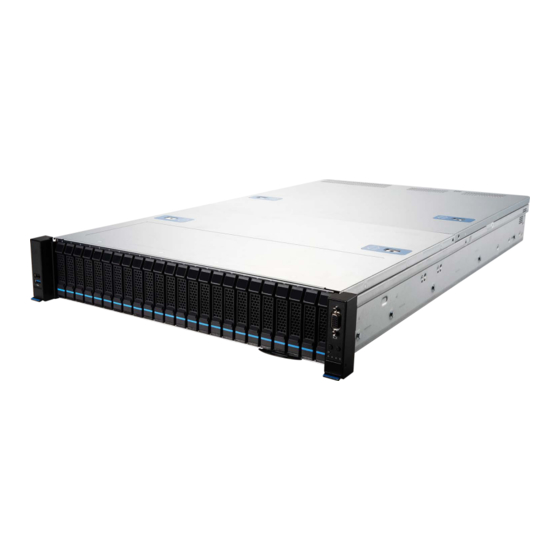
S2205 (2U24)
MS-S322
Server System
User Guide
Table of
Contents
Previous
Page
Next
Page
1
2
3
4
5
Advertisement
Table of Contents
Need help?
Do you have a question about the MS-S322 and is the answer not in the manual?
Ask a question
Questions and answers
Related Manuals for MSI MS-S322
Server MSI S2205 2U24 User Manual
(43 pages)
Server MSI S2206 2U24 User Manual
(42 pages)
Server MSI S2206 User Manual
(56 pages)
Server MSI S1102-01 User Manual
(39 pages)
Server MSI S1102-02 User Manual
(42 pages)
Server MSI MS-S2201 Manual
(36 pages)
Server MSI G3101 User Manual
(34 pages)
Server MSI G4101-01 User Manual
(55 pages)
Server MSI S1201 User Manual
(52 pages)
Server MSI E2101 User Manual
(24 pages)
Server MSI MS-S311 User Manual
Server system (54 pages)
Server MSI S1205 User Manual
Server system (55 pages)
Server MSI S2301 User Manual
(61 pages)
Server MSI CD270-S4051-X4 User Manual
(76 pages)
Server MSI S5063G480RAE20 User Manual
(56 pages)
Server MSI CD270-S4051-X2 User Manual
(78 pages)
This manual is also suitable for:
S2205
Table of Contents
Print
Rename the bookmark
Delete bookmark?
Delete from my manuals?
Login
Sign In
OR
Sign in with Facebook
Sign in with Google
Upload manual
Upload from disk
Upload from URL


Need help?
Do you have a question about the MS-S322 and is the answer not in the manual?
Questions and answers