Table of Contents
Advertisement
SMART POSITIONER
PRODUCT MANUAL
YT-3300 / 3350 / 3303 / 3301 / 3302 SERIES (New Software)
YT-3300 (New NCS type)
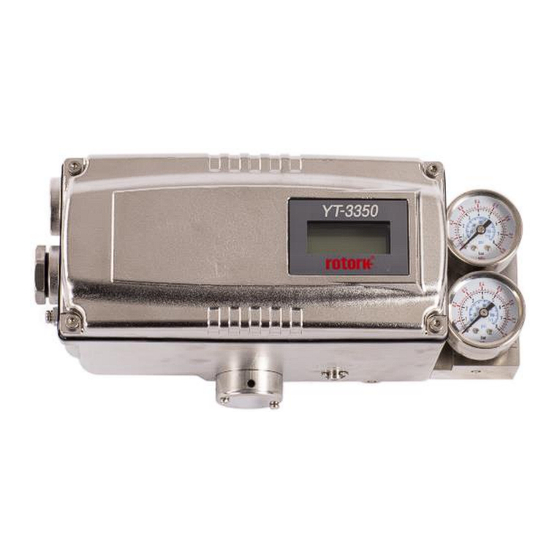
YT-3350 (New NCS type)
YT-3300 + Internal Limit Switch
YT-3303
(Potentiometer type)
(Potentiometer type)
YT-3301 (MS Connector Type)
(Potentiometer type)
YT-3302 (Junction Box Type)
(Potentiometer type)
Rotork YTC Limited
VERSION 2.12
Advertisement
Table of Contents

Subscribe to Our Youtube Channel
Related Manuals for rotork YT-3302 Series


Summary of Contents for rotork YT-3302 Series
- Page 1 YT-3300 / 3350 / 3303 / 3301 / 3302 SERIES (New Software) YT-3300 (New NCS type) YT-3350 (New NCS type) YT-3300 + Internal Limit Switch YT-3303 (Potentiometer type) (Potentiometer type) YT-3301 (MS Connector Type) (Potentiometer type) YT-3302 (Junction Box Type) (Potentiometer type) Rotork YTC Limited VERSION 2.12...
-
Page 2: Table Of Contents
Smart Positioner YT-3300 / 3350 / 3303 / 3301 / 3302 series (New Software) Product Manual Contents Introduction ..............................6 General Information for the users ......................6 Manufacturer Warranty .........................6 Explosion Proof Warning (Only for Intrinsic safety type positioners) ............7 Product Description ...........................9 General ..............................9 Main Features and Functions .......................9 Label Description .......................... - Page 3 Smart Positioner YT-3300 / 3350 / 3303 / 3301 / 3302 series (New Software) Product Manual 3.4.3 YT-3301R / 3302R remote sensor components ................46 3.4.4 Rotary Bracket Information (Only YT-3300R / 3350R / 3303R) ............ 47 3.4.5 Rotary positioner Installation Steps ....................48 Connection - Air ............................
- Page 4 Smart Positioner YT-3300 / 3350 / 3303 / 3301 / 3302 series (New Software) Product Manual 9.6.3 Auto Calibration 2 (AUTO 2) ......................75 9.6.4 Auto Calibration 3 (AUTO 3) ......................76 9.6.5 Travel Zero (TVL ZERO) and Travel end (TVL ENd) ..............77 Manual Operation (MAN OPER)......................
- Page 5 Smart Positioner YT-3300 / 3350 / 3303 / 3301 / 3302 series (New Software) Product Manual 9.11.6 Polling address setting (POL AddR) ..................100 9.11.7 Factory Reset (dEFAULT oFF / on) ..................101 9.11.8 Positioner Self-Test (SELFTEST) .................... 102 9.12 Diagnosis Mode (dIAGNd) .......................
-
Page 6: Introduction
Introduction General Information for the users Thank you for purchasing Rotork YTC Limited products. Each product has been fully inspected after its production to offer you the highest quality and reliable performance. Please read the product manual carefully prior to installing and commissioning the product. -
Page 7: Explosion Proof Warning (Only For Intrinsic Safety Type Positioners)
God, failure due to power surge, or cosmetic damage. Improper or incorrectly performed maintenance will void this limited warranty. For detailed warranty information, please contact the corresponding local Rotork YTC Limited ➢... - Page 8 Smart Positioner YT-3300 / 3350 / 3303 / 3301 / 3302 series (New Software) Product Manual ➢ For Intrinsically Safe installations, the product must be connected to suitably rated intrinsically safe equipment, and must be installed in accordance with applicable intrinsically safe installation standards.
-
Page 9: Product Description
Smart Positioner YT-3300 / 3350 / 3303 / 3301 / 3302 series (New Software) Product Manual Product Description General YT-3300 / 3350 / 3303 / 3301 / 3302 series Smart Valve Positioner accurately controls valve stroke in response to an input signal of 4 ~ 20 mA from the controller. Built-in micro-processor optimizes the positioner’s performance and provides unique functions such as Auto-Calibration, PID Control, and HART Protocol Communications. -
Page 10: Label Description
Smart Positioner YT-3300 / 3350 / 3303 / 3301 / 3302 series (New Software) Product Manual ➢ Hand calibration function can set Zero point or End point manually. It has IP66, Type 4X(FM) protection grade. ➢ ➢ Polyester powder coating resists the corrosion process. (except YT-3350). ➢... - Page 11 Smart Positioner YT-3300 / 3350 / 3303 / 3301 / 3302 series (New Software) Product Manual Fig. L-2: YT-3300 / 3303 / 3301 / 3302 Non-explosion proof (EAC) Fig. L-3: YT-3300 / 3303/ 3301 / 3302 Intrinsic safety type (UKEX, ATEX, IECEx, KCs, NEPSI, PESO) (PESO applies only to YT-3300) Fig.
- Page 12 Smart Positioner YT-3300 / 3350 / 3303 / 3301 / 3302 series (New Software) Product Manual Fig. L-5: YT-3301 Intrinsic safety type (FM, CSA) Fig. L-6: YT-3300 / 3303 / 3301 / 3302 Intrinsic safety type (EAC) Fig. L-7: YT-3300 / 3303 / 3301 / 3302 Intrinsic safety type (INMETRO) Ver.
- Page 13 Smart Positioner YT-3300 / 3350 / 3303 / 3301 / 3302 series (New Software) Product Manual Fig. L-8: YT-3300 Intrinsic safety type (CCC) Fig. L-9: YT-3303 Intrinsic safety type (CCC) Fig. L-10: YT-3301 Intrinsic safety type (CCC) Ver. 2.12...
- Page 14 Smart Positioner YT-3300 / 3350 / 3303 / 3301 / 3302 series (New Software) Product Manual Fig. L-11: YT-3302 Intrinsic safety type (CCC) Fig. L-12: YT-3350 Non-explosion proof Fig. L-13: YT-3350 Intrinsic safety type (UKEX, ATEX, IECEx, KCs, NEPSI) Ver. 2.12...
- Page 15 Smart Positioner YT-3300 / 3350 / 3303 / 3301 / 3302 series (New Software) Product Manual Fig. L-14: YT-3350 Intrinsic safety type (FM, CSA) Fig. L-15: YT-3350 Intrinsic safety type (EAC) Fig. L-16: YT-3350 Intrinsic safety type (INMETRO) Ver. 2.12...
-
Page 16: Product Code
Smart Positioner YT-3300 / 3350 / 3303 / 3301 / 3302 series (New Software) Product Manual Fig. L-17: YT-3350 Intrinsic safety type (CCC) Product Code YT-3300 / 3350 series follows suffix symbols as follows. 2.4.1 YT-3300 / 3350 1 Linear (Positioner is attached the right yoke of actuator.) Motion Type Rotary Single... - Page 17 Smart Positioner YT-3300 / 3350 / 3303 / 3301 / 3302 series (New Software) Product Manual 10 ~ 40 mm (Standard type) 20 ~ 100 mm (Standard type) 90 ~ 150 mm (Standard type) 16 ~ 30 mm (Adapter type) Linear 16 ~ 60 mm (Adapter type) 16 ~ 100 mm (Adapter type)
-
Page 18: Yt-3303 Series Follows Suffix Symbols As Follows
Smart Positioner YT-3300 / 3350 / 3303 / 3301 / 3302 series (New Software) Product Manual YT-3303 series follows suffix symbols as follows. 2.4.2 (YT-3303 has only a potentiometer type) YT-3303 1 Linear (Positioner is attached the left yoke of actuator.) Motion Type Rotary Single... -
Page 19: Yt-3301 / 3302 Series Follows Suffix Symbols As Follows
Smart Positioner YT-3300 / 3350 / 3303 / 3301 / 3302 series (New Software) Product Manual -30 ~ 85 °C (-22 ~ 185 °F, except EAC) Operating Temp. -40 ~ 85 °C (-40 ~ 185 °F) (Non-explosion proof) -55 ~ 85 °C (-67 ~ 185 °F, only EAC) In case of INMETRO, put “INMETRO”... - Page 20 Smart Positioner YT-3300 / 3350 / 3303 / 3301 / 3302 series (New Software) Product Manual None Communication + HART Communication None Option + Position Transmitter -30 ~ 85 °C (-22 ~ 185 °F, except EAC) Operating Temp. -40 ~ 85 °C (-40 ~ 185 °F) (Non-explosion proof) -55 ~ 85 °C (-67 ~ 185 °F, only EAC) Cable Length...
-
Page 21: Product Specification
Smart Positioner YT-3300 / 3350 / 3303 / 3301 / 3302 series (New Software) Product Manual Product Specification YT-3300 / 3303 / 3350 Specification 2.5.1 Model YT-3300 / 3303 YT-3350 Housing Material Aluminum Stainless Steel 316 Motion Type Linear Rotary Linear Rotary Acting Type... -
Page 22: Yt-3301 / 3302 Specification
5.1 kg (11.2 lb) Painting Polyester Powder Coating Tested under ambient temperature of 20 °C, absolute pressure of 760 mmHg, and humidity of 65 %. Please contact Rotork YTC Limited for detailed testing specification. YT-3301 / 3302 Specification 2.5.2 Model... - Page 23 1.0 kg (2.1 lb) Cable(5M) 0.6 kg (1.3 lb) Painting Polyester Powder Coating Tested under ambient temperature of 20 °C, absolute pressure of 760 mmHg, and humidity of 65 %. Please contact Rotork YTC Limited for detailed testing specification. Ver. 2.12...
-
Page 24: Certifications
Smart Positioner YT-3300 / 3350 / 3303 / 3301 / 3302 series (New Software) Product Manual Certifications ※ All certifications below are posted on Rotork YTC Limited homepage(www.ytc.co.kr). KCs (Korea) ➢ Type : Intrinsic safety Rating : Ex ia IIC T5/T6, Ex iaD T100°C/T85°C, IP66 Certification No. - Page 25 Smart Positioner YT-3300 / 3350 / 3303 / 3301 / 3302 series (New Software) Product Manual ➢ Rating : Class I, Div 1, Groups ABCD Class I, Zone 0 AEx ia IIC Class II/III, Div 1, Groups EFG Class I, II, III, Div 2, Groups ABCDFG NEMA Type 4X, IP66 (Only YT-3301: Positioner IP54, Feedback sensor Type 4X, IP66) Certificate No.: FM16US0268X...
- Page 26 Smart Positioner YT-3300 / 3350 / 3303 / 3301 / 3302 series (New Software) Product Manual SIL2 (in a redundant structure up to SIL 3) ➢ Intended application : Safety function is defined as to move into fail-safe-position, when signal to positioner is interrupted. Certification No.
-
Page 27: Parts And Assembly
Smart Positioner YT-3300 / 3350 / 3303 / 3301 / 3302 series (New Software) Product Manual Parts and Assembly YT-3300 / 3350 2.7.1 Fig. 2-1: YT-3300 / 3350 exploded view 1. Base Cover 7. Base body 2. PCB Cover 8. Pilot Block 3. - Page 28 Smart Positioner YT-3300 / 3350 / 3303 / 3301 / 3302 series (New Software) Product Manual YT-3303 2.7.2 Fig. 2-2: YT-3303 exploded view 1. Base Cover 7. Potentiometer 2. PCB Cover 8. Base body 3. Main PCB 9. Auto Manual Switch 4.
- Page 29 Smart Positioner YT-3300 / 3350 / 3303 / 3301 / 3302 series (New Software) Product Manual YT-3301 2.7.3 Positioner main body Rotary Remote Sensor Linear Remote Sensor Fig. 2-3: YT-3301 exploded view 1. Base cover of Positioner main body 9. Dome cover of Remote sensor 2.
- Page 30 Smart Positioner YT-3300 / 3350 / 3303 / 3301 / 3302 series (New Software) Product Manual YT-3302 2.7.4 Positioner main body Rotary Remote Sensor Linear Remote Sensor Fig. 2-4: YT-3302 exploded view 1. Base cover of Positioner main body 9. Remote cable 2.
-
Page 31: Product Dimension
Smart Positioner YT-3300 / 3350 / 3303 / 3301 / 3302 series (New Software) Product Manual Product Dimension YT-3300 2.8.1 Fig. 2-5: YT-3300L (Standard Lever Type) Fig. 2-6: YT-3300L (Adapter Lever Type) Fig. 2-7: YT-3300R (Fork lever Type) Fig. 2-8: YT-3300R+LS (Namur Type) Ver. - Page 32 Smart Positioner YT-3300 / 3350 / 3303 / 3301 / 3302 series (New Software) Product Manual YT-3350 2.8.2 Fig. 2-9: YT-3350L (Standard Lever Type) Fig. 2-10: YT-3350L (Adapter Lever Type) Fig. 2-11: YT-3350R (Fork lever Type) Fig. 2-12: YT-3350R+LS (Namur Type) Ver.
- Page 33 Smart Positioner YT-3300 / 3350 / 3303 / 3301 / 3302 series (New Software) Product Manual YT-3303 2.8.3 Fig. 2-13: YT-3303L Fig. 2-14: YT-3303R (Fork lever Type) Fig. 2-15: YT-3300R+LS (Namur Type) Ver. 2.12...
- Page 34 Smart Positioner YT-3300 / 3350 / 3303 / 3301 / 3302 series (New Software) Product Manual YT-3301 / 3302 2.8.4 Fig. 2-16: Linear Remote Sensor Fig. 2-17: Rotary Remote Sensor Fig. 2-18: YT-3301 Positioner main body Fig. 2-19: YT-3302 Positioner main body Ver.
-
Page 35: Installation
Smart Positioner YT-3300 / 3350 / 3303 / 3301 / 3302 series (New Software) Product Manual Installation Safety When installing a positioner, please ensure to read and follow safety instructions. ➢ Any input or supply pressures to valve, actuator, and / or to other related devices must be turned off. -
Page 36: Linear Positioner Installation
Smart Positioner YT-3300 / 3350 / 3303 / 3301 / 3302 series (New Software) Product Manual Linear positioner Installation Linear positioner should be installed on linear motion valves such as globe or gate type which uses spring return type diaphragm or piston actuators. Linear positioner Installation of Standard lever type 3.3.1 Fig. -
Page 37: 3.3.1.1 Safety
Smart Positioner YT-3300 / 3350 / 3303 / 3301 / 3302 series (New Software) Product Manual 3.3.1.1 Safety Proper bracket must be made in order to adapt the positioner on the actuator yoke. Please consider following important points when a bracket is being designed. ➢... - Page 38 Smart Positioner YT-3300 / 3350 / 3303 / 3301 / 3302 series (New Software) Product Manual 3) Connect connection bar to the actuator clamp. The hole gap on the feedback lever is 6.5 mm so the connection bar’s outer diameter should be less than 6 mm. 4) Connect an air-filter regulator to the actuator temporarily.
- Page 39 Smart Positioner YT-3300 / 3350 / 3303 / 3301 / 3302 series (New Software) Product Manual 6) Check if feedback lever is vertical to the valve stem at 50 % of the valve stroke. If it is not vertical, adjust the bracket or the connection bar to make vertical. Improper installation may cause poor linearity.
- Page 40 Smart Positioner YT-3300 / 3350 / 3303 / 3301 / 3302 series (New Software) Product Manual Stroke : 30 mm Stroke : 70 mm Fig. 3-15: YT-3303L / 3301L / 3302L Feedback lever and location of the connection bar 8) After installing the positioner, operate the valve from 0 % to 100 % stroke by using direct air to the actuator.
- Page 41 Smart Positioner YT-3300 / 3350 / 3303 / 3301 / 3302 series (New Software) Product Manual Fig. 3-17: YT-3303L / 3301L / 3302L Feedback lever should not touch lever stopper on 0 % ~ 100 % valve stroke. 9) After the installation, tighten all of the bolts on the bracket and the connection bar. Ver.
-
Page 42: Yt-3300L / 3350L Installation Of Adapter Lever Type (On Tubeless Actuator)
Smart Positioner YT-3300 / 3350 / 3303 / 3301 / 3302 series (New Software) Product Manual YT-3300L / 3350L Installation of Adapter lever type (on tubeless actuator) 3.3.2 Fig. 3-18: YT-3300L / 3350L installation of adapter lever type example Before proceeding with the installation, ensure following components are available. Positioner ➢... -
Page 43: 3.3.2.2 Adapter Lever Type Positioner Installation Steps
Smart Positioner YT-3300 / 3350 / 3303 / 3301 / 3302 series (New Software) Product Manual 3.3.2.2 Adapter lever type positioner Installation Steps 1) Remove Out1 Plug(Fig. 3-20) on the bottom of the positioner. Plug up out1 port of gauge block with 1/4 plug using sealant. - Page 44 Smart Positioner YT-3300 / 3350 / 3303 / 3301 / 3302 series (New Software) Product Manual Fig. 3-21: YT-3300 / 3350L(Adapter Lever Type) 5) Connect Air-filter regulator to Supply port of the positioner. 6) Turn the Auto/Manual switch counterclockwise (toward “M”). Refer to 6.2 for more detail. Supply enough air pressure to the actuator in order to position the valve stroke at 50 % of the total stroke.
-
Page 45: Rotary Positioner Installation
Smart Positioner YT-3300 / 3350 / 3303 / 3301 / 3302 series (New Software) Product Manual Rotary positioner Installation Rotary positioner should be installed on rotary motion valve such as ball or butterfly type which uses rack and pinion, scotch yoke or other type of actuators which its stem rotates 90 degrees. Before proceeding with the installation, ensure following components are available. -
Page 46: Yt-3303R Components
Smart Positioner YT-3300 / 3350 / 3303 / 3301 / 3302 series (New Software) Product Manual YT-3303R Components 3.4.2 ➢ Positioner ➢ Fork lever (Only Fork lever type) ➢ Rotary bracket set (2 piece) ➢ 4 pcs x hexagonal headed bolts (M8 x 1.25P) 4 pcs x M8 plate washers ➢... -
Page 47: Rotary Bracket Information (Only Yt-3300R / 3350R / 3303R)
Smart Positioner YT-3300 / 3350 / 3303 / 3301 / 3302 series (New Software) Product Manual Rotary Bracket Information (Only YT-3300R / 3350R / 3303R) 3.4.4 The rotary bracket set (included with the positioner) contains two components. (but the upper brackets of Fork lever type and Namur type are different in case of YT-3300 / 3350). -
Page 48: Rotary Positioner Installation Steps
Smart Positioner YT-3300 / 3350 / 3303 / 3301 / 3302 series (New Software) Product Manual Fig. 3-28: Actuator stem Height Fig. 3-29: Exploded Brackets Rotary positioner Installation Steps 3.4.5 1) Please check the actuator’s stem height and adjust the brackets by referring to the above bracket table. - Page 49 Smart Positioner YT-3300 / 3350 / 3303 / 3301 / 3302 series (New Software) Product Manual 5) (Only Fork lever type) After setting fork lever position, fasten lock nuts which are located on the bottom of the fork lever. Ensure to set the gap between the top of upper bracket and the top of the fork lever within 23 ~ 28 mm(YT-3300R / 3350R) and 6 ~ 11 mm(YT-3303R).
- Page 50 Smart Positioner YT-3300 / 3350 / 3303 / 3301 / 3302 series (New Software) Product Manual 7) (Only YT-3300 / 3350) After installing the positioner, operate the valve from 0 % to 100 % stroke by using direct air to the actuator. On both 0 % and 100 %, the indicator should not touch the indicator stopper, which is located on the backside of the positioner.
-
Page 51: Connection - Air
Smart Positioner YT-3300 / 3350 / 3303 / 3301 / 3302 series (New Software) Product Manual Connection - Air Safety ➢ Supply pressure should be clean and dry air – avoiding moisture, oil and dust. Always recommended to use air filter regulator (i.e. YT-200 series). ➢... -
Page 52: Connection - Piping With Actuator
Smart Positioner YT-3300 / 3350 / 3303 / 3301 / 3302 series (New Software) Product Manual Connection – Piping with actuator Single acting actuator 4.4.1 Singe acting type positioner is set to use only OUT1 port. OUT1 port of positioner should be connected with supply port of actuator when using spring return actuator of single acting type. -
Page 53: Double Acting Actuator
Smart Positioner YT-3300 / 3350 / 3303 / 3301 / 3302 series (New Software) Product Manual Double acting actuator 4.4.2 Double acting type positioner is set to use OUT1 and OUT2 port. As input signal increases, the supply pressure will be supplied through OUT1 port. Fig. -
Page 54: Connection - Power
Smart Positioner YT-3300 / 3350 / 3303 / 3301 / 3302 series (New Software) Product Manual Connection – Power Safety ➢ There are two conduit entries on the product. See “2.4 Product Code” for conduit entry threads. Before connecting terminal, ensure that the power is off completely. ➢... -
Page 55: Connection
Smart Positioner YT-3300 / 3350 / 3303 / 3301 / 3302 series (New Software) Product Manual Connection Standard Terminals 5.2.1 Terminal Signal name Function name Current input signal (+) Apply analog current command 4 ~ 20 mA to this terminal to supply power and signal to the positioner. Current input signal (-) Safety ground Safety ground... -
Page 56: Terminals With Micro-Limit Switch Option
Smart Positioner YT-3300 / 3350 / 3303 / 3301 / 3302 series (New Software) Product Manual Terminals with micro-limit switch option 5.2.2 The input and output terminals of products equipped with micro-limit switches can be connected to an external system as shown below. Refer to the table below for the signal name and function of each terminal. -
Page 57: Terminals With Inductive Proximity Limit Switch Option
Smart Positioner YT-3300 / 3350 / 3303 / 3301 / 3302 series (New Software) Product Manual Terminals with inductive proximity Limit Switch option 5.2.3 The input and output terminals of products equipped with inductive proximity limit switch switches can be connected to an external system as shown below. Refer to the table below for the signal name and function of each terminal. -
Page 58: Terminals Between Positioner Main Body And Remote Sensor Of Yt-3301 / 3302
Smart Positioner YT-3300 / 3350 / 3303 / 3301 / 3302 series (New Software) Product Manual Terminals between Positioner main body and Remote sensor of YT-3301 / 3302 5.2.4 Fig. 5-4: Remote sensor and cables Fig. 5-5: YT-3302 Positioner main body and cables Ground 1) Ground must be done before operating the positioner. -
Page 59: Adjustments
Smart Positioner YT-3300 / 3350 / 3303 / 3301 / 3302 series (New Software) Product Manual Adjustments Limit Switch Adjustment YT-3300 / 3350 can have limit switch option. If user wants to adjust the sensing positions, please loosen bolts and adjust cam. Fig. -
Page 60: A/M Switch Adjustment
Smart Positioner YT-3300 / 3350 / 3303 / 3301 / 3302 series (New Software) Product Manual A/M switch adjustment 1) On the right hand bottom of positioner, there is A/M switch (Auto/Manual). A/M Switch allows the positioner to be functioned as by-pass. If the switch is turned clockwise (toward “A”) and it is fasten tightly, then the supply pressure will be transferred to actuator through outport by positioner control. -
Page 61: Orifice Installment
Smart Positioner YT-3300 / 3350 / 3303 / 3301 / 3302 series (New Software) Product Manual Orifice Installment Hunting can be occurred when the actuator’s volume is too small. In order to prevent hunting, orifice can be used. Plate type Orifice Installment (except YT-3303) 6.3.1 By installing the plate type orifice, the flow rate of the supply pressure to actuator can be reduced. -
Page 62: Optional Sub-Pcb Installment
Smart Positioner YT-3300 / 3350 / 3303 / 3301 / 3302 series (New Software) Product Manual Optional Sub-PCB Installment By adding sub-PCB, the positioner can have additional functions. There are 3 types of sub-PCB. HART Only Ptm Only Ptm+HART Fig. 7-1: Three types of Sub-PCB When purchasing option sub-PCBs separately, 4 Bolts and 2 supports are supplied together with sub- PCB. - Page 63 Smart Positioner YT-3300 / 3350 / 3303 / 3301 / 3302 series (New Software) Product Manual Inductive proximity limit switch type (Only YT-3300 / 3350) Fig. 7-3: Installation of Option PCB on Main PCBs JP1 jumper must be removed, when HART option included sub-PCB is being mounted. 5) After PTM sub-PCB is installed newly, values of PTM ZERO and PTM ENd must be calibrated for correct output signals.
-
Page 64: Maintenance
Smart Positioner YT-3300 / 3350 / 3303 / 3301 / 3302 series (New Software) Product Manual Maintenance Supply air If Supply air pressure is not stable or Supply air is not clean, the positioner may not function properly. Air quality and pressure should be checked regularly to see if the air is clean and pressure set is normal. Seals Once a year, it is recommend to check if there are any damaged parts of the positioner. -
Page 65: Auto Calibration And Pcb Operation
Smart Positioner YT-3300 / 3350 / 3303 / 3301 / 3302 series (New Software) Product Manual Auto Calibration and PCB Operation Warning Following process will operate valve and actuator. Before proceeding with any Auto Calibration, please separate valve from the entire system by using bypass valve, so Auto Calibration will not affect entire valve process. -
Page 66: Button And Function
Smart Positioner YT-3300 / 3350 / 3303 / 3301 / 3302 series (New Software) Product Manual 9.2.2 Button and function Positioner has 4 buttons that perform various functions. Fig 9-2 Buttons Function Used to navigate to each menu at the same level or to increase the value of the selected parameter. -
Page 67: Menu Levels
Smart Positioner YT-3300 / 3350 / 3303 / 3301 / 3302 series (New Software) Product Manual Menu levels The basic menu structure consists of the RUN Mode Monitor and the Configuration/Operation. The Run Mode Monitor menu allows you to monitor the values of various variables. The Configuration/Operation menu provides calibration and tuning, manual operation, configuration of I/O port function, configuration and self-test of positioner, configuration of diagnostic function, and basic information of the positioner. -
Page 68: Run Mode (Run)
Smart Positioner YT-3300 / 3350 / 3303 / 3301 / 3302 series (New Software) Product Manual Run Mode (RUN) The RUN Mode Monitor is displayed on the LCD display when power is provided to the positioner. Pressing the UP/DOWN button scrolls through the various process variables shown in table below. -
Page 69: Configuration And Operation
Smart Positioner YT-3300 / 3350 / 3303 / 3301 / 3302 series (New Software) Product Manual Configuration and Operation The Table below shows the eight Configuration/Operation menus, each submenu, ranges for each parameter, and initial factory settings. The words shown in [ ] for each menu represent the abbreviations of each word displayed when operating the LCD screen. - Page 70 Smart Positioner YT-3300 / 3350 / 3303 / 3301 / 3302 series (New Software) Product Manual Level 1 Level 2 Range Initial factory setting Linear, Quick Open, Equal Percent, User Set Characterization [CHAR] 5point, User Set 21point [LIN, QO, EQ, U5, U21] User Set Characterization 5p 0 %, 25 %, 50 %, 75 %, 0 ~ 110[%]...
- Page 71 Smart Positioner YT-3300 / 3350 / 3303 / 3301 / 3302 series (New Software) Product Manual Level 1 Level 2 Range Initial factory setting View Event Log [EVT LOG] RECORd 0 - 19 View PST Result Record bLANK RECORd 1 - 10 [PST RSLT] INTERVAL, 365 d,...
- Page 72 Smart Positioner YT-3300 / 3350 / 3303 / 3301 / 3302 series (New Software) Product Manual Level 2 Level 3 Range Initial factory setting PST Interval [INTERVAL] 1 ~ 365 [days] PST Starting Position 0 ~ 100 [%] 100 % [START PO] PST Tolerance [TOL] 0.1 ~ 10 [%]...
-
Page 73: Calibration (Calib)
Smart Positioner YT-3300 / 3350 / 3303 / 3301 / 3302 series (New Software) Product Manual Calibration (CALIb) The calibration consists of five menus. Acting Type Set manually single or double acting by actuator type [SINGLE/ dOUbLE] Auto Calibration 1 [AUTO 1] Calibration on the zero and end points of the valve Auto Calibration 2 [AUTO 2] Calibration on all parameters required to operate the valve... -
Page 74: Acting Type (Single / Double)
Smart Positioner YT-3300 / 3350 / 3303 / 3301 / 3302 series (New Software) Product Manual Acting Type (SINGLE / dOUBLE) 9.6.1 This is used to change the settings of the positioner to SINGLE or dOUBLE, depending on the actuator type. -
Page 75: Auto Calibration 2 (Auto 2)
Smart Positioner YT-3300 / 3350 / 3303 / 3301 / 3302 series (New Software) Product Manual Auto Calibration 2 (AUTO 2) 9.6.3 AUTO 2 tunes up and then changes all parameters required for valve operation. Be sure to perform this AUTO 2 when installing the positioner on the valve for the first time or when reinstalling the positioner from the actuator. -
Page 76: Auto Calibration 3 (Auto 3)
Smart Positioner YT-3300 / 3350 / 3303 / 3301 / 3302 series (New Software) Product Manual Auto Calibration 3 (AUTO 3) 9.6.4 AUTO 3 tunes up and then changes all parameters required for valve operation. It is mainly used when valve characteristics change during valve operation or due to aging. -
Page 77: Travel Zero (Tvl Zero) And Travel End (Tvl End)
Smart Positioner YT-3300 / 3350 / 3303 / 3301 / 3302 series (New Software) Product Manual Travel Zero (TVL ZERO) and Travel end (TVL ENd) 9.6.5 This is a manual adjustment of the zero point or endpoint of the valve after auto calibration. Once you enter the TVL ZERO (or TVL ENd) setting, press the UP/DOWN button to change the zero point (or endpoint) of the valve, and then press the ENTER button to save it. -
Page 78: Manual Operation (Man Oper)
Smart Positioner YT-3300 / 3350 / 3303 / 3301 / 3302 series (New Software) Product Manual Manual Operation (MAN OPER) It is used to manually raise or lower the valve stem by operating the UP or DOWN buttons. This can be used to observe the move of valve stem without any external input signals. -
Page 79: Manual Operation By Manipulator Value (Man Mv)
Smart Positioner YT-3300 / 3350 / 3303 / 3301 / 3302 series (New Software) Product Manual Manual Operation by Manipulator Value (MAN MV) 9.7.2 The input to I/P converter is incremented or decremented by the UP and DOWN buttons based on the currently entered I/P input value, which moves the stem of the valve up and down. -
Page 80: Control Parameters (Ctl Parm)
Smart Positioner YT-3300 / 3350 / 3303 / 3301 / 3302 series (New Software) Product Manual Control Parameters (CTL PARM) Followings are the values changeable at the Control Parameters Mode. 1) Dead Band (dEAdbANd) 2) Forward P parameter (KP UP) and reverse P parameter (KP dN) 3) Forward Integral time parameter (TI UP) and reverse Integral time parameter (TI dN) 4) Forward D parameter (Kd UP) and reverse D parameter (Kd dN) 5) GAP Parameter (GAP) -
Page 81: Forward P Parameter (Kp Up) And Reverse P Parameter (Kp Dn)
Smart Positioner YT-3300 / 3350 / 3303 / 3301 / 3302 series (New Software) Product Manual Forward P parameter (KP UP) and reverse P parameter (KP dN) 9.8.2 The KP parameter is the proportional control constant to the calibration signal to reduce the error between the target position and the current position, the KP UP is applied when the valve moves in the direction of increasing output air pressure, and KP dN is applied when the valve moves in the direction of venting output air pressure. -
Page 82: Forward D Parameter (Kd Up) And Reverse D Parameter (Kd Dn)
Smart Positioner YT-3300 / 3350 / 3303 / 3301 / 3302 series (New Software) Product Manual Forward D parameter (Kd UP) and reverse D parameter (Kd dN) 9.8.4 The Kd parameter is a differential value that adds the correction signal due to the rate of error to the existing calibration signal. -
Page 83: Gap P Parameter (Gp)
Smart Positioner YT-3300 / 3350 / 3303 / 3301 / 3302 series (New Software) Product Manual GAP P parameter (GP) 9.8.6 GP is a proportional gain. If the valve position is within the GAP parameter range, a proportion gain created based on KP and GP is applied to valve control. 3 seconds →... -
Page 84: Auto Dead Band Mode (Auto Db)
Smart Positioner YT-3300 / 3350 / 3303 / 3301 / 3302 series (New Software) Product Manual Auto Dead band Mode (AUTO db) 9.8.9 This function is used to suppress a hunting for valves with high static friction. The initial value is OFF and it shall be set to 0 % to activate the auto dead band automatically. -
Page 85: Input Configuration (In Cfg)
Smart Positioner YT-3300 / 3350 / 3303 / 3301 / 3302 series (New Software) Product Manual Input Configuration (IN CFG) Followings are the values changeable at the Input Configuration Mode. 1) Signal Direction (SIG NORM / REVS) 2) Split Range Mode (SPLIT) 3) Custom Split Range Zero (CST ZERO) 4) Custom Split Range End (CST ENd) 5) Characterization Curves (CHAR) -
Page 86: Split Range Mode (Split)
Smart Positioner YT-3300 / 3350 / 3303 / 3301 / 3302 series (New Software) Product Manual Split Range Mode (SPLIT) 9.9.2 This is used to set the range of the input signal to control the entire stroke of the valve. You can select one of the four input signals that consists of 4 ~ 20 mA, 4 ~ 12 mA, 12 ~ 20 mA, and user settings (Custom, CSt). -
Page 87: Custom Split Range End (Cst End)
Smart Positioner YT-3300 / 3350 / 3303 / 3301 / 3302 series (New Software) Product Manual Custom Split Range End (CST ENd) 9.9.4 It is used to set the current corresponding to the endpoint when the valve position of 0 to 100 % is controlled by the user-set CUSTOM. -
Page 88: User Set Characterization 5 Points (U5)
Smart Positioner YT-3300 / 3350 / 3303 / 3301 / 3302 series (New Software) Product Manual User Set Characterization 5 Points (U5) 9.9.6 A total of 5 target positions are set every 4 mA intervals. When shipped from the factory, the initial positions are P0 (4 mA, 0 %), P1 (8 mA, 25 %), P2 (12 mA, 50 %), P3 (16 mA, 75 %), and P4 (20 mA, 100 %). -
Page 89: User Set Characterization 21 Points (U21)
Smart Positioner YT-3300 / 3350 / 3303 / 3301 / 3302 series (New Software) Product Manual User Set Characterization 21 Points (U21) 9.9.7 A total of 21 target points can be set every 0.8 mA intervals. When shipped from the factory, the initial P0 (4 mA, 0 %), P1 (4.8 mA, 5 %), P2 (5.6 mA 10 %), - - -, P19 (19.2 mA, 95 %), and P20 (20 mA, 100 %). -
Page 90: Tight Shut Open (Tshut Op)
Smart Positioner YT-3300 / 3350 / 3303 / 3301 / 3302 series (New Software) Product Manual Tight Shut Open (TSHUT OP) 9.9.8 It is used to ensure that the valve is fully opened with a large force. When the input signal SP is greater than the value set in the TSHUT OP, all available force is applied to OUT 1 port to tightly open the valve. -
Page 91: Tight Shut Close (Tshut Cl)
Smart Positioner YT-3300 / 3350 / 3303 / 3301 / 3302 series (New Software) Product Manual Tight Shut Close (TSHUT CL) 9.9.9 It is used to ensure that the valve is fully closed with a large force. When the input signal SP is smaller than the value set in the TSHUT CL, air pressure is vented through OUT 1 port to tightly close the valve. -
Page 92: Target Position Ramp Up Rate (Ramp Up) And Target Position Ramp Down Rate (Ramp Dn)
Smart Positioner YT-3300 / 3350 / 3303 / 3301 / 3302 series (New Software) Product Manual Target Position Ramp Up Rate (RAMP UP) and Target Position Ramp Down Rate (RAMP dN) 9.9.10 It is used to prevent the valve from moving too fast when the process to be controlled is too sensitive to rapid changes in flow or pressure. - Page 93 Smart Positioner YT-3300 / 3350 / 3303 / 3301 / 3302 series (New Software) Product Manual 3 seconds → → → Press <UP> or Press <UP> or <DOWN> button <DOWN> button if the above is not if the above is not displayed.
-
Page 94: Output Configuration (Out Cfg)
Smart Positioner YT-3300 / 3350 / 3303 / 3301 / 3302 series (New Software) Product Manual Output Configuration (OUT CFG) 9.10 Followings are the values changeable at the Output Configuration Mode. 1) Position Transmitter Direction (PTM NORM / REVS) 2) Position Transmitter Zero / End (PTM ZERO / ENd) 3) HART Feedback Direction (HT NORM / REVS) 4) Back Calculation (bACKCAL oFF / on) Position Transmitter Direction (PTM NORM / REVS) -
Page 95: Position Transmitter Zero / End (Ptm Zero / End)
Smart Positioner YT-3300 / 3350 / 3303 / 3301 / 3302 series (New Software) Product Manual Position Transmitter Zero / End (PTM ZERO / ENd) 9.10.2 ZERO adjusts the zero point of the position transmitter (4 mA feedback), and ENd adjusts the end point of the transmitter (20 mA feedback). -
Page 96: Hart Feedback Direction (Ht Norm / Revs)
Smart Positioner YT-3300 / 3350 / 3303 / 3301 / 3302 series (New Software) Product Manual <UP>/<DOWN> 3 seconds → → → Press <UP> or Adjusting zero The actuator <DOWN> button point. moves to zero if the above is not Press <UP>... -
Page 97: Back Calculation (Backcal Off / On)
Smart Positioner YT-3300 / 3350 / 3303 / 3301 / 3302 series (New Software) Product Manual Back Calculation (bACKCAL oFF / on) 9.10.4 This function recalculates the output "RUN AP" value changed by the flow characteristics setting mode to display it linearly proportional to actual input current. For example, if the flow characteristic mode is set from "LIN"... -
Page 98: Device Configuration (Dev Cfg)
Smart Positioner YT-3300 / 3350 / 3303 / 3301 / 3302 series (New Software) Product Manual Device Configuration (dEV CFG) 9.11 Followings are the values changeable at the dEV CFG Mode. 1) Action Setting (ACT REVS / dIR) 2) Linear Lever Type (STd / AdT) 3) Linear Interpolation (ITP oFF / on) 4) Lock of Parameters (Write Protect, W UNLOCK / LOCK) 5) Actual Position View Mode (View Mode, VI NORM / REVS) -
Page 99: Linear Interpolation (Itp Off / On)
Smart Positioner YT-3300 / 3350 / 3303 / 3301 / 3302 series (New Software) Product Manual Linear Interpolation (ITP oFF / on) 9.11.3 ITP is used to compensate the linear motion of the actuator into rotary motion of the feedback lever. Following Auto Calibration, the ITP mode is set automatically to “on”... -
Page 100: Actual Position View Mode (View Mode, Vi Norm / Revs)
Smart Positioner YT-3300 / 3350 / 3303 / 3301 / 3302 series (New Software) Product Manual Actual Position View Mode (View Mode, VI NORM / REVS) 9.11.5 This function is used to set the "RUN AP" value on the LCD to be displayed as direct (NORM) or reversely (REVS) as the actual position of the valve. -
Page 101: Factory Reset (Default Off / On)
Smart Positioner YT-3300 / 3350 / 3303 / 3301 / 3302 series (New Software) Product Manual Factory Reset (dEFAULT oFF / on) 9.11.7 This function initializes all parameters stored in the positioner to initial factory setting. In the dEFAULT mode, press the Enter button to enables ON/OFF setting and then pressing Enter button for approximately 3 seconds changes the dEFAULT mode from oFF to “on". -
Page 102: Positioner Self-Test (Selftest)
Smart Positioner YT-3300 / 3350 / 3303 / 3301 / 3302 series (New Software) Product Manual Positioner Self-Test (SELFTEST) 9.11.8 This function is used to diagnose the operation of the memory (RAM or NVM) inside the positioner. If no error is found during SELFTEST, the SELFTEST menu is displayed after FINISH is displayed, and if abnormalities are detected, the message "SEt / NVMW"... -
Page 103: Diagnosis Mode (Diagnd)
Smart Positioner YT-3300 / 3350 / 3303 / 3301 / 3302 series (New Software) Product Manual Diagnosis Mode (dIAGNd) 9.12 Followings are the values changeable at the dIAGNO Mode. 1) Default Alarm Settings 2) Process Status (PS) 3) Device Status (dS) 4) View Monitoring Counts (VI CNTS) 5) Diagnostic Limit Configuration (LIMT CFG) 6) Reset Alarm Status (RST ALRM) -
Page 104: Default Alarm Settings
Smart Positioner YT-3300 / 3350 / 3303 / 3301 / 3302 series (New Software) Product Manual Default Alarm Settings 9.12.1 The table below shows the initial values set at factory for handling the positioner status or associated process conditions. Each status or alarm is set to one of the Failure, Out of Specification, Maintenance Required, or Functional Check at factory, so that the corresponding NE107 symbol is displayed when a specific alarm occurs. -
Page 105: Process Status (Ps)
Smart Positioner YT-3300 / 3350 / 3303 / 3301 / 3302 series (New Software) Product Manual Process Status (PS) 9.12.2 The status of the current process is indicated as GOOd, NE107 symbol, and abbreviation for alarm. NE107 symbols Function Abbreviation None PS GOOd Good... -
Page 106: Device Status (Ds)
Smart Positioner YT-3300 / 3350 / 3303 / 3301 / 3302 series (New Software) Product Manual Device Status (dS) 9.12.3 The status of the current device is indicated as GOOd, NE107 symbol, and abbreviation for alarm. NE107 symbols Function Abbreviation None dS GOOd Good... -
Page 107: View Monitoring Counts (Vi Cnts)
Smart Positioner YT-3300 / 3350 / 3303 / 3301 / 3302 series (New Software) Product Manual View Monitoring Counts (VI CNTS) 9.12.4 It is used to just view the accumulated data information for valve movement up to now. Counter Name Abbreviation [unit] Function The accumulated number of times the valve has changed its... -
Page 108: Diagnostic Limit Configuration (Limt Cfg)
Smart Positioner YT-3300 / 3350 / 3303 / 3301 / 3302 series (New Software) Product Manual Diagnostic Limit Configuration (LIMT CFG) 9.12.5 This configuration is used to set the upper or lower limit that is generated by the Travel High Limit Alarm and Travel Low Limit Alarm. -
Page 109: Reset Alarm Status (Rst Alrm Off / On)
Smart Positioner YT-3300 / 3350 / 3303 / 3301 / 3302 series (New Software) Product Manual Reset Alarm Status (RST ALRM oFF / on) 9.12.6 The alarm is automatically released when the cause of the alarm is removed. For example, if the Partial Stroke Test fails or Auto Calibration fails, use this function to release the alarm. -
Page 110: View Event Log (Evt Log)
Smart Positioner YT-3300 / 3350 / 3303 / 3301 / 3302 series (New Software) Product Manual View Event Log (EVT LOG) 9.12.7 This is used to show the 20 most recent events that occurred in operation. Record 0 is the most recent of the 20 events and Record 19 is the oldest event. -
Page 111: Partial Stroke Test Record (View Pst Result Record, Pst Rslt)
Smart Positioner YT-3300 / 3350 / 3303 / 3301 / 3302 series (New Software) Product Manual Partial Stroke Test Record (View PST Result Record, PST RSLT) 9.12.8 This is used to show information about the 10 most recent Partial Stroke Tests performed. Record 1 is the most recent of the 10 PST histories, and Record 10 is the result of the oldest PST operation. -
Page 112: Pst Configuration (Pst Cfg)
Smart Positioner YT-3300 / 3350 / 3303 / 3301 / 3302 series (New Software) Product Manual PST Configuration (PST CFG) 9.12.9 Parameter names Abbreviation [unit] Description Sets time interval PST is triggered. Initial factory setting PST Interval INTERVAL [days] is 365 days. Sets the start position to launch PST. -
Page 113: Run Pst (Pst Now)
Smart Positioner YT-3300 / 3350 / 3303 / 3301 / 3302 series (New Software) Product Manual 3 seconds → → → Press <UP> or Press <UP> or <DOWN> button <DOWN> button if the above is not if the above is not displayed. -
Page 114: Periodic Pst Test (Pst Schedule, Pst Schd Off / On)
Smart Positioner YT-3300 / 3350 / 3303 / 3301 / 3302 series (New Software) Product Manual 9.12.11 Periodic PST Test (PST Schedule, PST SCHd oFF / on) When PST SCHd is set to ON, the Partial Stroke Test is executed regularly under the conditions set in 9.12.9 above. - Page 115 Smart Positioner YT-3300 / 3350 / 3303 / 3301 / 3302 series (New Software) Product Manual LCD display Description YT3300L Model Name Software Version [SOFT VER] “4.0.00” Software Input date : “2022-01(JA)-31” 4.0.00 (January JA, February FB, March MR, April AR, May MY, June JN, July JL, SOFT VER August AG, September SP, October OT, November NV, December DC) 2022JA31...
-
Page 116: Error Codes During Automatic Calibration
Smart Positioner YT-3300 / 3350 / 3303 / 3301 / 3302 series (New Software) Product Manual Error codes during automatic calibration 9.14 The error detected during the automatic calibration is displayed on LCD especially when the positioner may become out of control, may malfunction or may become poor in precision. Once it is detected, the auto calibration is aborted. -
Page 117: Status And Alarm Code
Smart Positioner YT-3300 / 3350 / 3303 / 3301 / 3302 series (New Software) Product Manual Status and Alarm Code 9.15 Refer to the table below to check the status and alarm codes that can be displayed on LCD screen or HART monitor, and then take the appropriate action. - Page 118 Smart Positioner YT-3300 / 3350 / 3303 / 3301 / 3302 series (New Software) Product Manual Alarm Abbreviation Status / Alarm name Description or proposed actions Code It is active when auto-calibration has not done after NCAL Not Calibrated installation. Perform AUTO 2 calibration after checking if the installed state is good.
-
Page 119: Main Software Map
Smart Positioner YT-3300 / 3350 / 3303 / 3301 / 3302 series (New Software) Product Manual Main Software Map Ver. 2.12... - Page 120 Product Manual Manufacturer: Rotork YTC Limited Address: 81, Hwanggeum-ro, 89 Beon-gil, Yangchon-eup, Gimpo-si, Gyeonggi-do, South Korea Postal code: 10048 Tel: +82-31-986-8545 Fax: +82-70-4170-4927 Email: ytc.sales@rotork.com Homepage : http://www.ytc.co.kr Issued : 2023-09-26 Copyright © Rotork YTC Limited. All Rights Reserved. Ver. 2.12...
Need help?
Do you have a question about the YT-3302 Series and is the answer not in the manual?
Questions and answers