
Related Manuals for rotork YT-3700


Summary of Contents for rotork YT-3700
- Page 1 SMART POSITIONER PRODUCT MANUAL YT-3700 / 3750 YT-3700 YT-3750 Rotork YTC Limited VERSION 1.03...
-
Page 2: Table Of Contents
Smart Positioner YT-3700 / 3750 Product Manual Contents Introduction ..............................5 General Information for the users ......................5 Manufacturer Warranty .........................5 Explosion Proof Warning (Only for Intrinsic safety type positioners) ............6 Product Description ...........................7 General ..............................7 Main Features and Functions .......................7 Label Description ..........................8 Product Code ............................. - Page 3 Smart Positioner YT-3700 / 3750 Product Manual 5.2.3 Terminals with proximity Limit Switch option ................. 35 Ground ............................... 35 Adjustments ............................. 36 Limit Switch Adjustment ........................36 A/M switch adjustment ........................37 Orifice Installment ..........................38 6.3.1 Plate type Orifice Installment ......................38 Optional Sub-PCB Installment ........................
- Page 4 Smart Positioner YT-3700 / 3750 Product Manual 8.9.8 Tight Shut Open (TSHUT OP) ....................... 63 8.9.9 Tight Shut Close (TSHUT CL) ....................... 64 8.9.10 Target Position Ramp Up Rate (RAMP UP) and Target Position Ramp Down Rate (RAMP dN) 8.9.11 Digital Input Function (dIF) ......................
-
Page 5: Introduction
Introduction General Information for the users Thank you for purchasing Rotork YTC Limited products. Each product has been fully inspected after its production to offer you the highest quality and reliable performance. Please read the product manual carefully prior to installing and commissioning the product. -
Page 6: Explosion Proof Warning (Only For Intrinsic Safety Type Positioners)
été enlevées ou la zone est connue pour être non dangereux. ➢ The enclosure of model YT-3700 contains aluminum, which is considered to constitute a potential risk of ignition when subjected to impact or friction. Care must be used during installation in locating this equipment to prevent impact or friction ➢... -
Page 7: Product Description
Product Description General YT-3700 / 3750 series Smart Valve Positioner accurately controls valve stroke in response to an input signal of 4~20mA from the controller. Built-in micro-processor optimizes the positioner’s performance and provides unique functions such as Auto-Calibration, PID Control, and HART Protocol Communications. -
Page 8: Label Description
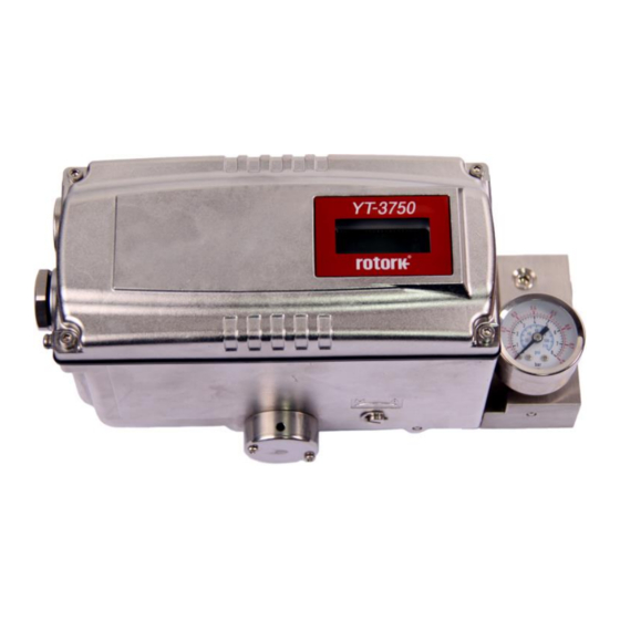
You can also see the details in the certificate. ※ Precautions Be careful not to apply volatile solvent (hardener of instant adhesive, acetone, WD-40, etc.) to the sticker nameplate. Printed contents may be erased. Fig. L-1: YT-3700 Non-explosion proof Ver. 1.03... - Page 9 Smart Positioner YT-3700 / 3750 Product Manual Fig. L-2: YT-3700 Intrinsic safety type (ATEX, IECEx, KCs, NEPSI) Fig. L-3: YT-3700 Intrinsic safety type (FM, CSA) Fig. L-4: YT-3700 Non-explosion proof (TRCU) Ver. 1.03...
- Page 10 Smart Positioner YT-3700 / 3750 Product Manual Fig. L-5: YT-3700 Intrinsic safety type (TRCU) Fig. L-6: YT-3700 Intrinsic safety type (INMETRO) Fig. L-7: YT-3750 Non-explosion proof Ver. 1.03...
- Page 11 Smart Positioner YT-3700 / 3750 Product Manual Fig. L-8: YT-3750 Intrinsic safety type (ATEX, IECEx, KCs, NEPSI) Fig. L-9: YT-3750 Intrinsic safety type (FM, CSA) Fig. L-10: YT-3750 Intrinsic safety type (TRCU) Ver. 1.03...
- Page 12 Smart Positioner YT-3700 / 3750 Product Manual Fig. L-11: YT-3750 Intrinsic safety type (INMETRO) Ver. 1.03...
-
Page 13: Product Code
Smart Positioner YT-3700 / 3750 Product Manual Product Code YT-3700 / 3750 1 Linear Motion Type Rotary Single Acting type Double Non-Explosion Explosion Proof ATEX, IECEx, KCs, NEPSI, INMETRO : Ex ia IIC T5/T6 Gb, Ex ia IIIC T100℃/T85℃ Db, IP66 FM &... -
Page 14: Product Specification
※ N/A at Limit switch options. Weight 2 kg (4.4 lb) 5.1 kg (11.2 lb) Painting Epoxy Polyester Powder Coating Tested under ambient temperature of 20°C, absolute pressure of 760mmHg, and humidity of 65%. Please contact Rotork YTC Limited for detailed testing specification. Ver. 1.03... -
Page 15: Specification Of Digital In, Digital Out
Smart Positioner YT-3700 / 3750 Product Manual Specification of Digital In, Digital out 1) Digital In • Control voltage : 0 ~ 5V DC Logical switching state "0" 11 ~ 28V DC Logical switching state "1" • Current Max. 4mA 2) Digital Out •... -
Page 16: Certifications
Smart Positioner YT-3700 / 3750 Product Manual Certifications ※ All certifications below are posted on Rotork YTC Limited homepage(www.ytc.co.kr). ➢ KCs (Korea, Pending) Type : Intrinsic safety Rating : Ex ia IIC T5/T6, Ex iaD T100℃/T85℃, IP66 Certification No. : XX-KA2BO-XXXXX(YT-3700) - Page 17 Smart Positioner YT-3700 / 3750 Product Manual ➢ CSA (Pending) Type : Intrinsic safety Rating : Class I, Division 1&2 Groups ABCD T5/T6 Class II, Division 1&2 Groups EFG T100℃/T85℃ Class III Ex ia IIC T5/T6 Ga Ex tb IIIC T100℃/T85℃ Db IP66 Certificate No.: CSA XX.XXXXXXXX...
-
Page 18: Parts And Assembly
Smart Positioner YT-3700 / 3750 Product Manual Parts and Assembly Fig. 2-1: Exploded view of standard type positioner 1. Base Cover 7. Base body 2. PCB Cover 8. Pilot Block 3. Main PCB 9. Auto Manual Switch 4. Torque Motor 10. - Page 19 Smart Positioner YT-3700 / 3750 Product Manual Fig. 2-2: Exploded view of limit switch type positioner 1. Base Cover 8. Potentiometer 2. PCB Cover 9. Base body 3. Main PCB(limit switch type) 10. Pilot Block 4. Torque Motor 11. Auto Manual Switch 5.
-
Page 20: Product Dimension
Smart Positioner YT-3700 / 3750 Product Manual Product Dimension 2.9.1 YT-3700 Fig. 2-3: YT-3700L Fig. 2-4: YT-3700R+LS 2.9.2 YT-3750 Fig. 2-5: YT-3750L Fig. 2-6: YT-3750R+LS Ver. 1.03... -
Page 21: Installation
Smart Positioner YT-3700 / 3750 Product Manual Installation Safety When installing a positioner, please ensure to read and follow safety instructions. ➢ Any input or supply pressures to valve, actuator, and / or to other related devices must be turned off. -
Page 22: Linear Positioner Installation
Smart Positioner YT-3700 / 3750 Product Manual Linear positioner Installation Linear positioner should be installed on linear motion valves such as globe or gate type which uses spring return type diaphragm or piston actuators. 3.3.1 Linear positioner Installation of Standard lever type Fig. -
Page 23: Standard Lever Type Positioner Installation Steps
Smart Positioner YT-3700 / 3750 Product Manual 3.3.3 Standard lever type positioner Installation Steps 1. Assemble the positioner or remote sensor with the bracket made in previous step by fastening the bolts. Fig. 3-3: Linear positioner, bracket, actuator 2. Attach the positioner with the bracket to the actuator yoke –... - Page 24 Smart Positioner YT-3700 / 3750 Product Manual 5. Insert the connection bar between the feedback lever and lever spring. The connection bar must be located upward from the lever spring as shown below left figure. If it is located downward from the lever spring as shown below right figure, the connection bar or the lever spring will be worn out quickly because of excessive strong tension.
- Page 25 Smart Positioner YT-3700 / 3750 Product Manual 7. Check the valve stroke. The stroke numbers are engraved on the feedback lever of the positioner. Position the connection bar at the number on the feedback lever which corresponds with the desired valve stroke. To adjust, move the bracket, the connection bar or both.
-
Page 26: Rotary Positioner Installation
Smart Positioner YT-3700 / 3750 Product Manual Rotary positioner Installation Rotary positioner should be installed on rotary motion valve such as ball or butterfly type which uses rack and pinion, scotch yoke or other type of actuators which its stem rotates 90 degrees. Before proceeding with the installation, ensure following components are available. -
Page 27: Rotary Bracket Information
Smart Positioner YT-3700 / 3750 Product Manual 3.4.2 Rotary Bracket Information The rotary bracket set (included with the positioner) contains two components. The bracket is designed to fit onto the actuator with 20mm, 30mm and 50mm stem height (H) according to VDI/VDE 3845 standard. -
Page 28: Rotary Positioner Installation Steps
Smart Positioner YT-3700 / 3750 Product Manual Fig. 3-11: Actuator stem Height Fig. 3-12: Exploded Brackets 3.4.3 Rotary positioner Installation Steps 1. Please check the actuator’s stem height and adjust the brackets by referring to the above bracket table. 2. Attached the brackets onto the actuator. It is recommended to use spring washer so the bolts will not be loosen from vibration. -
Page 29: Connection - Air
Supply pressure should be clean and dry air – avoiding moisture, oil and dust. ➢ Always recommended to use air filter regulator (i.e. YT-200 series). Rotork YTC Limited has not tested positioner’s operation with any other gases other than ➢ clean air. Please contact Rotork YTC Limited for any questions. -
Page 30: Connection - Piping With Actuator
Smart Positioner YT-3700 / 3750 Product Manual Connection – Piping with actuator 4.4.1 Single acting actuator Singe acting type positioner is set to use only OUT1 port. OUT1 port of positioner should be connected with supply port of actuator when using spring return actuator of single acting type. -
Page 31: Connection - Power
Smart Positioner YT-3700 / 3750 Product Manual Connection – Power Safety ➢ Before connecting terminal, ensure that the power is off completely. ➢ Please use ring terminal to protect against vibration or any other external impact. ➢ Positioner usually uses 4~20mA DC. Minimum ampere of input signal is 3.8 mA but maximum ampere of input signal should be 24mA or under. -
Page 32: Connection
Smart Positioner YT-3700 / 3750 Product Manual Connection 5.2.1 Standard Terminals The input/output terminals of the basic model are connected to an external system as shown below. Refer to the table below for the signal name and function of each terminal. - Page 33 Smart Positioner YT-3700 / 3750 Product Manual Terminal Signal name Function name Current input signal (+) Apply analog current command 4 - 20 mA to this terminal to supply power and signal to the positioner. Current input signal (-) Safety ground...
-
Page 34: Terminals With Micro-Limit Switch Option
Smart Positioner YT-3700 / 3750 Product Manual 5.2.2 Terminals with micro-limit switch option The input and output terminals of products equipped with micro-limit switches can be connected to an external system as shown below. Refer to the table below for the signal name and function of each terminal. -
Page 35: Terminals With Proximity Limit Switch Option
Smart Positioner YT-3700 / 3750 Product Manual 5.2.3 Terminals with proximity Limit Switch option The input and output terminals of products equipped with proximity limit switch switches can be connected to an external system as shown below. Refer to the table below for the signal name and function of each terminal. -
Page 36: Adjustments
YT-3700 / 3750 Product Manual Adjustments Limit Switch Adjustment YT-3700 / 3750 can have limit switch option. If user wants to adjust the sensing position, please loosen bolts and adjust cam. Fig. 6-1: Mechanical Type Fig. 6-2: Proximity Type Ver. 1.03... -
Page 37: A/M Switch Adjustment
Smart Positioner YT-3700 / 3750 Product Manual A/M switch adjustment 1. On the right hand bottom of positioner, there is A/M switch (Auto/Manual). A/M Switch allows the positioner to be functioned as by-pass. If the switch is turned clockwise (toward “A”) and it is fasten tightly, then the supply pressure will be transferred to actuator through outport by positioner control. -
Page 38: Orifice Installment
Smart Positioner YT-3700 / 3750 Product Manual Orifice Installment Hunting can be occurred when the actuator’s volume is too small. In order to prevent hunting, orifice can be used. 6.3.1 Plate type Orifice Installment By installing the plate type orifice, the flow rate of the supply pressure to actuator can be reduced. -
Page 39: Optional Sub-Pcb Installment
By adding sub-PCB, the positioner can have additional functions. There are 3 types of sub-PCB. Hart Only Ptm Only Ptm+Hart Fig. 7-1: Three types of Sub-PCB of YT-3700 / 3701 / 3703 / 3750 When purchasing option sub-PCBs separately, 4 Bolts and 2 supports are supplied together with sub-PCB. Installation steps 1. - Page 40 Smart Positioner YT-3700 / 3750 Product Manual Proximity Limit switch type Fig. 7-3: Installation of Option PCB on Main PCBs JP1 jumper must be removed, when HART option included sub-PCB is being mounted. 5. After PTM sub-PCB is installed newly, values of PTM ZERO and PTM ENd must be calibrated for correct output signals.
-
Page 41: Auto Calibration And Pcb Operation
Smart Positioner YT-3700 / 3750 Product Manual Auto Calibration and PCB Operation Warning Following process will operate valve and actuator. Make sure to disconnect the Valve from the system prior to the automatic calibration (AutoCal) to prevent any disruption of the process since this operation shall move the Valve and Actuator. -
Page 42: Button And Function
Smart Positioner YT-3700 / 3750 Product Manual 8.2.2 Button and function Positioner has 4 buttons, and they enable to perform various functions. Fig. 8-2 Buttons Function Used to navigate to each menu at the same level or to increase the value of the selected parameter. -
Page 43: Menu Levels
Smart Positioner YT-3700 / 3750 Product Manual Menu levels The basic menu structure consists of the RUN Mode Monitor and the Configuration/Operation. The Run Mode Monitor menu allows you to monitor the values of various variables. The Configuration/Operation menu provides calibration and tuning, manual operation, configuration of I/O port function, configuration and self-test of positioner, configuration of diagnostic function, and basic information of the positioner. -
Page 44: Run Mode Monitor
Smart Positioner YT-3700 / 3750 Product Manual RUN Mode Monitor The RUN Mode Monitor is displayed on the LCD display when power is provided to the positioner. Pressing the UP/DOWN button scrolls through the various process variables shown in table below. A "30.0%" in the LCD display below indicates that the valve is in the 30% position, and an "AP"... -
Page 45: Configuration And Operation
Smart Positioner YT-3700 / 3750 Product Manual Configuration and Operation The Table below shows the eight Configuration/Operation menus, each submenu, ranges for each parameter, and initial factory settings. The words shown in [ ] for each menu represent the abbreviations of each word displayed when operating the LCD screen. - Page 46 Smart Positioner YT-3700 / 3750 Product Manual Initial factory setting Level 1 Level 2 Range Input Configuration Linear, Quick Open, [IN CFG] Equal Percent, User Set Characterization [CHAR] 5point, User Set 21point [LIN, QO, EQ, U5, U21] User Set Characterization 5p...
- Page 47 Smart Positioner YT-3700 / 3750 Product Manual Initial factory setting Level 1 Level 2 Range Diagnosis [dIAGNO] Process Status [PS] GOOd, FAIL, FUNC, GOOd OUTS, MNTR Device Status [dS] GOOd, Refer to 8.14 GOOd Status and Alarm Code. View Monitoring Counts...
- Page 48 Smart Positioner YT-3700 / 3750 Product Manual The Table below identifies the range and initial factory settings of each parameter for Menu Level 2 and Menu Level 3 where the menu hierarchy has been lowered by one level. Initial factory setting...
-
Page 49: Calibration (Calib)
Smart Positioner YT-3700 / 3750 Product Manual Calibration (CALIb) The calibration consists of five menus. Calibration Acting Type Set manually single or double acting by actuator type [CALIb] [SINGLE/ dOUbLE] Auto Calibration 1 [AUTO 1] Calibration on the zero and end points of the valve... -
Page 50: Auto Calibration 1 (Auto 1)
Smart Positioner YT-3700 / 3750 Product Manual 8.6.2 Auto Calibration 1 (AUTO 1) AUTO 1 is used to set only the origin and end points. It does not change the PID and other parameter values that already have been set. This is usually used when the origin and end points of the already calibrated positioner have changed slightly. -
Page 51: Travel Zero (Tvl Zero) And Travel End (Tvl End)
Smart Positioner YT-3700 / 3750 Product Manual 8.6.4 Travel Zero (TVL ZERO) and Travel end (TVL ENd) This is a manual adjustment of the zero point or endpoint of the valve after auto calibration. Once you enter the TRAVEL ZERO (or TRAVE END) setting, press the UP/DOWN button to change the zero point (or endpoint) of the valve, and then press the ENTER button to save it. -
Page 52: Manual Operation (Man Oper)
Smart Positioner YT-3700 / 3750 Product Manual Manual Operation (MAN OPER) It is use to manually raise or lower the valve stem by operating the UP or DOWN buttons. This can be used to observe the move of valve stem without any external input signals. When engaged, the current input signal to the positioner has no effect on the positioner. -
Page 53: Manual Operation By Mv (Man Mv)
Smart Positioner YT-3700 / 3750 Product Manual 8.7.2 Manual Operation by MV (MAN MV) The input to I/P converter is incremented or decremented by the UP and DOWN buttons based on the currently entered I/P input value, which moves the stem of the valve up and down. Once out of the menu by <ESC>, the positioner is controlled again by an input signal. -
Page 54: Control Parameters (Ctl Parm)
Smart Positioner YT-3700 / 3750 Product Manual Control Parameters (CTL PARM) Followings are the values changeable at the Control Parameters Mode. 1) Dead Band (dEAdbANd) 2) Forward P parameter (KP UP) and reverse P parameter (KP dN) 3) Forward Integral time parameter (TI UP) and reverse Integral time parameter (TI dN) -
Page 55: Forward P Parameter (Kp Up) And Reverse P Parameter (Kp Dn)
Smart Positioner YT-3700 / 3750 Product Manual 8.8.2 Forward P parameter (KP UP) and reverse P parameter (KP dN) The KP parameter is the proportional control constant to the calibration signal to reduce the error between the target position and the current position, the KP UP is applied when the valve moves in the direction of increasing output air pressure, and KP dN is applied when the valve moves in the direction of venting output air pressure. -
Page 56: Forward D Parameter (Kd Up) And Reverse D Parameter (Kd Dn)
Smart Positioner YT-3700 / 3750 Product Manual 8.8.4 Forward D parameter (Kd UP) and reverse D parameter (Kd dN) The Kd parameter is a differential value that adds the correction signal due to the rate of error to the existing calibration signal. Kd UP is applied when the valve moves in the direction of increasing output air pressure, and Kd dN is applied when the valve moves in the direction of decreasing output air pressure. -
Page 57: Performance Mode (Per)
Smart Positioner YT-3700 / 3750 Product Manual 8.8.6 Performance Mode (PER) This mode has three modes of operation: Stable, Normal, and Fast that allow you to select the required responsiveness. The gains settings are accomplished from low response to fast response in the order of Stable, Normal, and Fast. -
Page 58: Input Configuration(In Cfg)
Smart Positioner YT-3700 / 3750 Product Manual Input Configuration(IN CFG) Followings are the values changeable at the Input Configuration Mode. 1) Signal Direction (SIG NORM / REVS) 2) Split Range Mode (SPLIT) 3) Custom Split Range Zero (CST ZERO) 4) Custom Split Range End (CST ENd) -
Page 59: Split Range Mode (Split)
Smart Positioner YT-3700 / 3750 Product Manual 8.9.2 Split Range Mode (SPLIT) This is used to set the range of the input signal to control the entire stroke of the valve. You can select one of the four input signals that consists of 4-20 mA, 4-12 mA, 12-20 mA, and user settings (Custom, CSt). -
Page 60: Custom Split Range End (Cst End)
Smart Positioner YT-3700 / 3750 Product Manual 8.9.4 Custom Split Range End (CST ENd) It is used to set the current corresponding to the endpoint when the valve position of 0 to 100% is controlled by the user-set CUSTOM. For example, if the valve is controlled by 4-18 mA instead of 4- 20 mA, CST END is 17 mA. -
Page 61: User Set Characterization 5 Points (U5)
Smart Positioner YT-3700 / 3750 Product Manual 8.9.6 User Set Characterization 5 Points (U5) A total of 5 target positions are set every 4 mA intervals. When shipped from the factory, the initial positions are P0 (4mA, 0%), P1 (8mA, 25%), P2 (12mA, 50%), P3 (16mA, 75%), and P4 (20mA, 100%). -
Page 62: User Set Characterization 21 Points (U21)
Smart Positioner YT-3700 / 3750 Product Manual 8.9.7 User Set Characterization 21 Points (U21) A total of 21 target points can be set every 0.8 mA intervals. When shipped from the factory, the initial P0 (4mA, 0%), P1 (4.8 mA, 5%), P2 (5.6 mA 10%), - - -, P19 (19.2 mA, 95%), and P20 (20 mA, 100%). -
Page 63: Tight Shut Open (Tshut Op)
Smart Positioner YT-3700 / 3750 Product Manual 8.9.8 Tight Shut Open (TSHUT OP) It is used to ensure that the valve is fully opened with a large force. When the input signal SP is greater than the value set in the TSHUT OP, all available force is applied to OUT 1 port to tightly open the valve. -
Page 64: Tight Shut Close (Tshut Cl)
Smart Positioner YT-3700 / 3750 Product Manual 8.9.9 Tight Shut Close (TSHUT CL) It is used to ensure that the valve is fully closed with a large force. When the input signal SP is smaller than the value set in the TSHUT CL, air pressure is vented through OUT 1 port to tightly close the valve. -
Page 65: Target Position Ramp Up Rate (Ramp Up) And Target Position Ramp Down Rate (Ramp Dn)
Smart Positioner YT-3700 / 3750 Product Manual 8.9.10 Target Position Ramp Up Rate (RAMP UP) and Target Position Ramp Down Rate (RAMP dN) It is used to prevent the valve from moving too fast when the process to be controlled is too sensitive to rapid changes in flow or pressure. - Page 66 Smart Positioner YT-3700 / 3750 Product Manual 3 seconds Press <UP> or Press <UP> or <DOWN> button <DOWN> button if the above is not if the above is not displayed. displayed. <UP>/<DOWN> <ESC> <DOWN> ...
-
Page 67: Digital Input Function (Dif)
Smart Positioner YT-3700 / 3750 Product Manual 8.9.11 Digital Input Function (dIF) It is used to perform a specific function as the signal is activated on the digital input port. The configuration of dIF and di LOGIC is needed. Function name... -
Page 68: Output Configuration (Out Cfg)
Smart Positioner YT-3700 / 3750 Product Manual 8.10 Output Configuration (OUT CFG) Followings are the values changeable at the Output Configuration Mode. 1) Position Transmitter Direction (PTM NORM / REVS) 2) Position Transmitter Zero / End (PTM ZERO / ENd) -
Page 69: Position Transmitter Zero / End (Ptm Zero / End)
Smart Positioner YT-3700 / 3750 Product Manual 8.10.2 Position Transmitter Zero / End (PTM ZERO / ENd) ZERO adjusts the zero point of the position transmitter (4mA feedback), and ENd adjusts the end point of the transmitter (20mA feedback). This is used when the analog output signal needs to be feedbacked differently than the actual position of the valve, or to be adjusted a little. -
Page 70: Hart Feedback Direction (Ht Norm / Revs)
Smart Positioner YT-3700 / 3750 Product Manual <UP>/<DOWN> 3 seconds Press <UP> or Adjusting zero The actuator <DOWN> button point. moves to zero if the above is not Press <UP> or point. displayed. <DOWN> button if the above is not displayed. -
Page 71: Back Calculation (Backcal Off / On)
Smart Positioner YT-3700 / 3750 Product Manual 8.10.4 Back Calculation (bACKCAL oFF / on) This function recalculates the output "RUN AP" value changed by the flow characteristics setting mode to display it linearly proportional to actual input current. For example, if the flow characteristic mode is set from "LIN"... -
Page 72: Digital Output Function (Dof)
Smart Positioner YT-3700 / 3750 Product Manual 8.10.5 Digital Output Function (dOF) This is used to output a specific alarm through the digital output port when triggered. Any of the alarms below can be configured to activate digital output. Assign any alarm to one of four NE107 signals to activate a digital output even when several alarms are triggered. -
Page 73: Digital Output Logic (Do Logic Hi / Lo)
Smart Positioner YT-3700 / 3750 Product Manual 8.10.6 Digital Output Logic (dO LOGIC HI / Lo) This logic function activates digital output to High (HI) or Low (Lo). The initial factory setting is HI, which means that when 11 - 28 V DC voltage is applied, the output current will be in the range of 2.2 to 14 mA flowing through the output port. -
Page 74: Analog Output Function (Aof)
Smart Positioner YT-3700 / 3750 Product Manual 8.10.7 Analog Output Function (AOF) This is used to output a specific alarm through the analog output port when triggered. If one of the alarms below occurs, it can be configured so that the analog output is activated. Assign any alarm to one of the four NE107 signals to activate an analog output signal required for any of the listed alarms. -
Page 75: Analog Output Logic (Ao Logic Lo / Hi)
Smart Positioner YT-3700 / 3750 Product Manual 8.10.8 Analog Output Logic (AO LOGIC Lo / HI) This logic function activates the analog output to High (HI) or Low (Lo). A current of less than 3.6 mA is sourced from the analog output port when the initial factory setting is low (Lo) with an external voltage source applied to the analog output. -
Page 76: Device Configuration (Dev Cfg)
Smart Positioner YT-3700 / 3750 Product Manual 8.11 Device Configuration (dEV CFG) Followings are the values changeable at the dEV CFG Mode. 1) Action Setting (ACT REVS / dIR) 2) Linear Interpolation (ITP oFF / on) 3) Lock of Parameters (Write Protect, W UNLOCK / LOCK) -
Page 77: Linear Interpolation (Itp Off / On)
Smart Positioner YT-3700 / 3750 Product Manual 8.11.2 Linear Interpolation (ITP oFF / on) ITP is used to compensate the linear motion of the actuator into rotary motion of the feedback lever. Following Auto Calibration, the ITP mode is set automatically to ON when the angle range of the feedback lever is greater than 20°, but it is set to OFF when this angle is less than 20°... -
Page 78: Actual Position View Mode (View Mode, Vi Norm / Revs)
Smart Positioner YT-3700 / 3750 Product Manual 8.11.4 Actual Position View Mode (View Mode, VI NORM / REVS) This function is used to set the "RUN AP" value on the LCD to be displayed as direct (NORM) or reversely (REVS) as the actual position of the valve. -
Page 79: Factory Reset (Default Off / On)
Smart Positioner YT-3700 / 3750 Product Manual 8.11.6 Factory Reset (dEFAULT oFF / on) This function initializes all parameters stored in the positioner to initial factory setting. In the dEFAULT mode, pressing the Enter button for approximately 3 seconds enables ON/OFF setting mode and then setting it to ON resets all parameters. -
Page 80: Positioner Self-Test (Selftest)
Smart Positioner YT-3700 / 3750 Product Manual 8.11.7 Positioner Self-Test (SELFTEST) This function is used to diagnose the operation of the memory (RAM or NVM) inside the positioner. If no error is found during SELFTEST, the SELFTEST menu is displayed after FINISH is displayed, and if abnormalities are detected, the message "SEt / NVMW"... -
Page 81: Diagnosis Mode (Diagnd)
Smart Positioner YT-3700 / 3750 Product Manual 8.12 Diagnosis Mode (dIAGNd) Followings are the values changeable at the dIAGNO Mode. 1) Default Alarm Settings 2) Process Status (PS) 3) Device Status (dS) 4) View Monitoring Counts (VI CNTS) 5) Diagnostic Limit Configuration (LIMT CFG) - Page 82 Smart Positioner YT-3700 / 3750 Product Manual Is the Status or Alarm reset Status / Alarm Activation NE107 signals manually? Cycle Count Limit Disable Maintenance Required Travel Accumulate Limit Disable Maintenance Required Operating Count Limit Disable Maintenance Required Temperature High Limit...
-
Page 83: Process Status (Ps)
Smart Positioner YT-3700 / 3750 Product Manual 8.12.2 Process Status (PS) The status of the current process is indicated as GOOd, NE107 symbol, and abbreviation for alarm. NE107 symbols Abbreviation Function None PS GOOd Good PS FAIL Failure PS FUNC... -
Page 84: Device Status (Ds)
Smart Positioner YT-3700 / 3750 Product Manual <ESC> 3 seconds 2 times Press <UP> or Press <UP> or <DOWN> button <DOWN> button if the above is not if the above is not displayed. displayed. 8.12.3 Device Status (dS) The status of the current process is indicated as GOOd, NE107 symbol, and abbreviation for alarm. - Page 85 Smart Positioner YT-3700 / 3750 Product Manual Process Alarm Abbreviation Loop Operation Active LOPA Auto Calibration Running CALR PST Running PSTR Diagnosis Running dIGR Position Sensor High Limit PSNH Position Sensor Low Limit PSNL Critical NVM Fail NVMF Non-Critical NVM Fail...
-
Page 86: View Monitoring Counts (Vi Cnts)
Smart Positioner YT-3700 / 3750 Product Manual 8.12.4 View Monitoring Counts (VI CNTS) It is used to view the accumulated data information for valve movement up to now. Counter Name Abbreviation [unit] Function Cycle Count CYCL CNT The accumulated number of times the valve has changed its direction. -
Page 87: Diagnostic Limit Configuration (Limt Cfg)
Smart Positioner YT-3700 / 3750 Product Manual 8.12.5 Diagnostic Limit Configuration (LIMT CFG) This configuration is used to set the upper or lower limit that is generated by the Travel High Limit Alarm, Travel Low Limit Alarm, Temperature High Limit Alarm, Temperature Low Limit Alarm, and Deviation Timeout Alarm. -
Page 88: Reset Alarm Status (Rst Alrm Off / On)
Smart Positioner YT-3700 / 3750 Product Manual 8.12.6 Reset Alarm Status (RST ALRM oFF / on) The alarm is automatically released when the cause of the alarm is removed. For example, if a high- temperature alarm is created, the alarm is automatically released when internal temperature drops below the Temperature High Limit. -
Page 89: View Event Log (Evt Log)
Smart Positioner YT-3700 / 3750 Product Manual 8.12.7 View Event Log (EVT LOG) This is used to show the 20 most recent events that occurred in operation. Record 0 is the most recent of the 20 events and Record 19 is the oldest event. The event detail can be viewed in EVT INFO as well as the time of the event in EVT TIME, time when the event occurred. -
Page 90: Partial Stroke Test Record (View Pst Result Record, Pst Rslt)
Smart Positioner YT-3700 / 3750 Product Manual 8.12.8 Partial Stroke Test Record (View PST Result Record, PST RSLT) This is used to show information about the 10 most recent Partial Stroke Tests performed. Record 1 is the most recent of the 10 PST histories, and Record 10 is the result of the oldest PST operation. -
Page 91: Pst Configuration (Pst Cfg)
Smart Positioner YT-3700 / 3750 Product Manual 8.12.9 PST Configuration (PST CFG) Parameter names Abbreviation [unit] Description PST Interval INTERVAL [days] Sets time interval PST is triggered. Initial factory setting is 365 days. PST Start Position START PO [%] Sets the start position to launch PST. Initial factory setting is 100 %. -
Page 92: Run Pst (Pst Now)
Smart Positioner YT-3700 / 3750 Product Manual 3 seconds Press <UP> or Press <UP> or <DOWN> button <DOWN> button if the above is not if the above is not displayed. displayed. <UP>/<DOWN> <ESC> 4 times ... -
Page 93: Periodic Pst Test (Pst Schedule, Pst Schd Off / On)
Smart Positioner YT-3700 / 3750 Product Manual 8.12.11 Periodic PST Test (PST Schedule, PST SCHd oFF / on) When PST SCHd is set to ON, the Partial Stroke Test is executed regularly under the conditions set in 5.7.9 above. For example, PST is performed every 365 days when PST Interval is set to 365 days. -
Page 94: Position Information (Info)
Smart Positioner YT-3700 / 3750 Product Manual 8.13 Position information (INFO) The diverse Positioner information is provided in the INFO Mode. <DOWN> 3 seconds Press <UP> or <DOWN> button if the above is not displayed. <DOWN> <DOWN>... - Page 95 Smart Positioner YT-3700 / 3750 Product Manual LCD display Description YT3700L Model Name Software Version [SOFT VER] “1.0.00” 1.0.00 Software Input date : “2019 MA 21” SOFT VER At SOFT VER status if button is pressed, the date will be displayed and then if 2019MA21 button is pressed again, SOFT VER is displayed again.
-
Page 96: Status And Alarm Code
Smart Positioner YT-3700 / 3750 Product Manual 8.14 Status and Alarm Code The status and alarm codes can be displayed on the LCD screen as required. Refer to the table below to check the status and alarm codes, and then take the appropriate action.(See 8.5... - Page 97 Smart Positioner YT-3700 / 3750 Product Manual Alarm Abbreviation Status / Alarm name Description or proposed actions Code TVLH Travel Hi Limit It is active when the travel exceeds Travel Hi Limit. TVLL Travel Lo Limit It is active when the travel falls below Travel Lo Limit.
- Page 98 Smart Positioner YT-3700 / 3750 Product Manual Alarm Abbreviation Status / Alarm name Description or proposed actions Code Replace the electronics board by contacting the STAK Stack Overflow manufacturer or manufacturer’s representative. It is active if the HART related communication errors...
-
Page 99: Main Software Map
Smart Positioner YT-3700 / 3750 Product Manual Main Software Map Ver. 1.03... - Page 100 Product Manual Manufacturer: Rotork YTC Limited Address: 81, Hwanggeum-ro, 89 Beon-gil, Yangchon-eup, Gimpo-si, Gyeonggi-do, South Korea Postal code: 10048 Tel: +82-31-986-8545 Fax: +82-70-4170-4927 Email: ytc.sales@rotork.com Homepage : http://www.ytc.co.kr Issued : 2019-08-13 Copyright © Rotork YTC Limited. All Rights Reserved. Ver. 1.03...
Need help?
Do you have a question about the YT-3700 and is the answer not in the manual?
Questions and answers
При открытии клапана на 40+- процентов уходит в ошибку PS LPCl 37
The error PS LPCL 37 on the Rotork YT-3700 indicates "Loop Current Low," meaning the loop input current is below 3.8 mA. This can occur regardless of the valve position, including when the valve is opened to approximately 40 percent.
This answer is automatically generated