Table of Contents
Advertisement
Advertisement
Table of Contents

Related Manuals for rotork YT-3100


Summary of Contents for rotork YT-3100
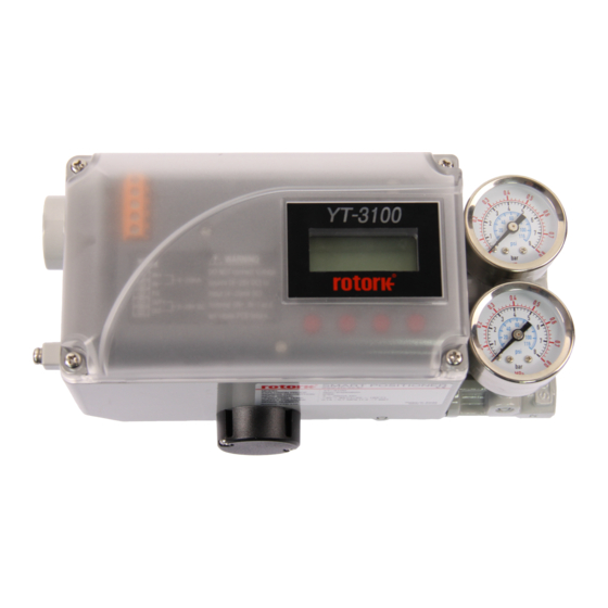
- Page 1 SMART POSITIONER PRODUCT MANUAL YT-3100 Rotork YTC Limited VERSION 1.19...
-
Page 2: Table Of Contents
Smart Positioner YT-3100 Product Manual Contents Introduction ..............................5 General Information for the users ......................5 Manufacturer Warranty .........................5 Explosion Proof Warning (Only for Intrinsic safety type positioners) ............6 Product Description ...........................7 General ..............................7 Main Features and Functions .......................7 Label Description ..........................8 Product Code ............................. - Page 3 Smart Positioner YT-3100 Product Manual Installation steps ..........................28 Maintenance ............................. 29 Supply air ............................29 Seals ..............................29 Auto Calibration and PCB Operation ..................... 30 Warning .............................. 30 LCD display and buttons ........................30 9.2.1 LCD display and symbols ......................30 9.2.2...
- Page 4 Smart Positioner YT-3100 Product Manual 9.10.3 Back Calculation (bACKCAL oFF / on) ..................53 9.11 Device Configuration (dEV CFG)....................... 54 9.11.1 Action Setting (ACT) ........................54 9.11.2 Linear Interpolation (ITP oFF / on)..................... 55 9.11.3 Lock of Parameters (Write Protect, W UNLOCK / LOCK) ............55 9.11.4...
-
Page 5: Introduction
Introduction General Information for the users Thank you for purchasing Rotork YTC Limited products. Each product has been fully inspected after its production to offer you the highest quality and reliable performance. Please read the product manual carefully prior to installing and commission the product. -
Page 6: Explosion Proof Warning (Only For Intrinsic Safety Type Positioners)
Smart Positioner YT-3100 Product Manual Explosion Proof Warning (Only for Intrinsic safety type positioners) Please ensure the unit is being used and installed in conformity with local, regional, and national explosion proof within the proper safety barrier environment. ➢ Refer to “2.6 Certifications”... -
Page 7: Product Description
Product Manual Product Description General YT-3100 Smart Valve Positioner accurately controls valve stroke in response to an input signal of 4 ~ 20 mA from the controller. Built-in micro-processor optimizes the positioner’s performance and provides unique functions such as Auto-Calibration, PID Control. -
Page 8: Label Description
Smart Positioner YT-3100 Product Manual Label Description • MODEL : Indicates the model number and any options of the positioner. • EXPLOSION PROOF : Indicates certified explosion proof grade. • INGRESS PROTECTION : Indicates enclosure protection grade. • INPUT SIGNAL : Indicates input signal range. - Page 9 Smart Positioner YT-3100 Product Manual Fig. L-3: Intrinsic safety type (CCC) Ver. 1.19...
-
Page 10: Product Code
Smart Positioner YT-3100 Product Manual Product Code YT-3100 follows suffix symbols as follows. YT-3100 1 Linear (Positioner is attached the right yoke of actuator.) Motion Type Rotary Single Acting type Double Non-Explosion Ex ia IIC T5/T6 Gb : ATEX, IECEx, KCs, NEPSI... -
Page 11: Product Specification
Weight 1.7 kg (3.7 lb) Painting of base body Polyester Powder Coating Tested under ambient temperature of 20 °C, absolute pressure of 760 mmHg, and humidity of 65 %. Please contact Rotork YTC Limited for detailed testing specification. Ver. 1.19... -
Page 12: Certifications
Smart Positioner YT-3100 Product Manual Certifications ※ All certifications below are posted on YTC homepage(www.ytc.co.kr). KCs (Korea) ➢ Type : Intrinsic safety Rating : Ex ia IIC T5/T6 Certification No. : 19-KA2BO-0502X Ambient temperature : -30 ~ +60°C (T5), -30 ~ +40°C (T6) ATEX ➢... -
Page 13: Parts And Assembly
Smart Positioner YT-3100 Product Manual Parts and Assembly Fig. 2-1: exploded view 1. Base Cover 6. Pilot 2. PCB Cover 7. Pilot Block 3. Main PCB 8. Base body 4. Torque Motor 9. Feedback Lever 5. Main Shaft 10. Gauge Block... -
Page 14: Product Dimension
Smart Positioner YT-3100 Product Manual Product Dimension Fig. 2-2: YT-3100L Fig. 2-3: YT-3100R Ver. 1.19... -
Page 15: Installation
Smart Positioner YT-3100 Product Manual Installation Safety When installing a positioner, please ensure to read and follow safety instructions. ➢ Any input or supply pressures to valve, actuator, and / or to other related devices must be turned off. ➢... -
Page 16: Linear Positioner Installation
Smart Positioner YT-3100 Product Manual Linear positioner Installation Linear positioner should be installed on linear motion valves such as globe or gate type which uses spring return type diaphragm or piston actuators. Fig. 3-2: installation example Before proceeding with the installation, ensure following components are available. -
Page 17: Standard Lever Type Positioner Installation Steps
Smart Positioner YT-3100 Product Manual Standard lever type positioner Installation Steps 3.3.2 1) Assemble the positioner with the bracket made in previous step by fastening the bolts. Fig. 3-3: Linear (Standard Lever Type) 2) Attach the positioner with the bracket to the actuator yoke –... - Page 18 Smart Positioner YT-3100 Product Manual 4) Connect an air-filter regulator to the actuator temporarily. Supply enough air pressure to the actuator in order to position the valve stroke at 50 % of the total stroke. Fig. 3-4: Linear (Standard Lever Type) 5) Insert the connection bar between the feedback lever and lever spring.
- Page 19 Smart Positioner YT-3100 Product Manual 6) Check if feedback lever is vertical to the valve stem at 50 % of the valve stroke. If it is not vertical, adjust the bracket or the connection bar to make vertical. Improper installation may cause poor linearity.
- Page 20 Smart Positioner YT-3100 Product Manual 8) After installing the positioner, operate the valve from 0 % to 100 % stroke by using direct air to the actuator. On both 0 % and 100 %, the feedback lever should not touch the lever stopper, which is located on the backside of the positioner.
-
Page 21: Rotary Positioner Installation
Smart Positioner YT-3100 Product Manual Rotary positioner Installation Rotary positioner should be installed on rotary motion valve such as ball or butterfly type which uses rack and pinion, scotch yoke or other type of actuators which its stem rotates 90 degrees. Before proceeding with the installation, ensure following components are available. -
Page 22: Rotary Bracket Information
Smart Positioner YT-3100 Product Manual Rotary Bracket Information 3.4.2 The rotary bracket set (included with the positioner) contains two components. (but the upper brackets of Fork lever type and Namur type are different). The bracket is designed to fit onto the actuator with 20 mm, 30 mm and 50 mm stem height (H) according to VDI/VDE 3845 standard. -
Page 23: Rotary Positioner Installation Steps
Smart Positioner YT-3100 Product Manual Fig. 3-11: Actuator stem Height Fig. 3-12: Exploded Brackets Rotary positioner Installation Steps 3.4.3 1) Please check the actuator’s stem height and adjust the brackets by referring to the above bracket table. 2) Attached the brackets onto the actuator. It is recommended to use spring washer so the bolts will not be loosen from vibration. -
Page 24: Connection - Air
➢ Always recommended to use air filter regulator (i.e. YT-200 series). ➢ Rotork YTC Limited has not tested positioner’s operation with any other gases other than clean air. Please contact Rotork YTC Limited for any questions. Supply Pressure Condition ➢... -
Page 25: Double Acting Actuator
Smart Positioner YT-3100 Product Manual Double acting actuator 4.4.2 Double acting type positioner is set to use OUT1 and OUT2 port. As input signal increases, the supply pressure will be supplied through OUT1 port. Fig. 4-3: Double acting linear actuator Fig. -
Page 26: Connection - Power
Smart Positioner YT-3100 Product Manual Connection – Power Safety ➢ There is a conduit entry on the product. See “2.4 Product Code” for conduit entry thread. ➢ Before connecting terminal, ensure that the power is off completely. ➢ Please use ring terminal to protect against vibration or any other external impact. -
Page 27: Ground
Smart Positioner YT-3100 Product Manual Ground 1) Ground must be done before operating the positioner. 2) Open base cover and there is an internal ground “F.G” on the left hand. An external ground bolt is located next to the conduit entry. Please make sure that the resistance is less than 100 ohm. -
Page 28: Optional Sub-Pcb Installment
Smart Positioner YT-3100 Product Manual Optional Sub-PCB Installment By adding sub-PCB, the positioner can have an additional PTM(position transmitter) function. Fig. 7-1: Sub-PCB of PTM When purchasing option a sub-PCB separately, 4 Bolts and 2 supports are supplied together with sub- PCB. -
Page 29: Maintenance
Smart Positioner YT-3100 Product Manual Maintenance Supply air If Supply air pressure is not stable or Supply air is not clean, the positioner may not function properly. Air quality and pressure should be checked regularly to see if the air is clean and pressure set is normal. -
Page 30: Auto Calibration And Pcb Operation
Smart Positioner YT-3100 Product Manual Auto Calibration and PCB Operation Warning Following process will operate valve and actuator. Make sure to disconnect the Valve from the system prior to the automatic calibration (AutoCal) to prevent any disruption of the process since this operation shall move the Valve and Actuator. -
Page 31: Button And Function
Smart Positioner YT-3100 Product Manual Button and function 9.2.2 Positioner has 4 buttons, and they enable to perform various functions. Fig. 9-2: Buttons Function Used to navigate to each menu at the same level or to increase the value of the selected parameter. -
Page 32: Menu Levels
Smart Positioner YT-3100 Product Manual Menu levels The basic menu structure consists of the RUN Mode Monitor and the Configuration/Operation. The Run Mode Monitor menu allows you to monitor the values of various variables. The Configuration/Operation menu provides calibration and tuning, manual operation, configuration of I/O port function, configuration and self-test of positioner, configuration of diagnostic function, and basic information of the positioner. -
Page 33: Run Mode Monitor
Smart Positioner YT-3100 Product Manual RUN Mode Monitor The RUN Mode Monitor is displayed on the LCD display when power is provided to the positioner. Pressing the UP/DOWN button scrolls through the various process variables shown in table below. A "30.0%" in the LCD display below indicates that the valve is in the 30 % position, and an "AP"... -
Page 34: Configuration And Operation
Smart Positioner YT-3100 Product Manual Configuration and Operation The Table below shows the eight Configuration/Operation menus, each submenu, ranges for each parameter, and initial factory settings. The words shown in [ ] for each menu represent the abbreviations of each word displayed when operating the LCD screen. - Page 35 Smart Positioner YT-3100 Product Manual Initial factory setting Level 1 Level 2 Range Linear, Quick Open, Equal Percent, User Set Characterization [CHAR] 5point, User Set 21point [LIN, QO, EQ, U5, U21] User Set Characterization 5p 0 %, 25 %, 50 %, 75 %,...
-
Page 36: Calibration (Calib)
Smart Positioner YT-3100 Product Manual Calibration (CALIb) The calibration consists of five menus. Acting Type Set manually single or double acting by actuator type [SINGLE/ dOUbLE] Auto Calibration 1 [AUTO 1] Calibration on the zero and end points of the valve... -
Page 37: Auto Calibration 1 (Auto 1)
Smart Positioner YT-3100 Product Manual Auto Calibration 1 (AUTO 1) 9.6.2 AUTO 1 is used to set only the origin and end points. It does not change the PID and other parameter values that already have been set. This is usually used when the origin and end points of the already calibrated positioner have changed slightly. -
Page 38: Travel Zero (Tvl Zero) And Travel End (Tvl End)
Smart Positioner YT-3100 Product Manual Travel Zero (TVL ZERO) and Travel end (TVL ENd) 9.6.4 This is a manual adjustment of the zero point or endpoint of the valve after auto calibration. Once you enter the TRAVEL ZERO (or TRAVE END) setting, press the UP/DOWN button to change the zero point (or endpoint) of the valve, and then press the ENTER button to save it. -
Page 39: Manual Operation (Man Oper)
Smart Positioner YT-3100 Product Manual Manual Operation (MAN OPER) It is used to manually raise or lower the valve stem by operating the UP or DOWN buttons. This can be used to observe the move of valve stem without any external input signals. When engaged, the current input signal to the positioner has no effect on the positioner. -
Page 40: Manual Operation By Mv (Man Mv)
Smart Positioner YT-3100 Product Manual Manual Operation by MV (MAN MV) 9.7.2 The input to I/P converter is incremented or decremented by the UP and DOWN buttons based on the currently entered I/P input value, which moves the stem of the valve up and down. Once out of the menu by <ESC>, the positioner is controlled again by an input signal. -
Page 41: Control Parameters (Ctl Parm)
Smart Positioner YT-3100 Product Manual Control Parameters (CTL PARM) Followings are the values changeable at the Control Parameters Mode. 1) Dead Band (dEAdbANd) 2) Forward P parameter (KP UP) and reverse P parameter (KP dN) 3) Forward Integral time parameter (TI UP) and reverse Integral time parameter (TI dN) -
Page 42: Forward Integral Time Parameter (Ti Up) And Reverse Integral Time Parameter (Ti Dn)
Smart Positioner YT-3100 Product Manual Forward Integral time parameter (TI UP) and reverse Integral time parameter (TI dN) 9.8.3 TI parameters are an integral value that add the error correction signal to the existing calibration signal, TI UP is applied when the valve moves in the direction of increasing the output air pressure, and TI DN is applied when the valve moves in the direction of decreasing the output air pressure. -
Page 43: Auto Dead Band Mode (Auto Db)
Smart Positioner YT-3100 Product Manual Auto Dead band Mode (AUTO db) 9.8.5 This function is used to suppress a hunting for valves with high static friction. The initial value is OFF and it shall be set to 0 % to activate the auto dead band automatically. The value is changed to a proper value once this mode is activated. -
Page 44: Input Configuration (In Cfg)
Smart Positioner YT-3100 Product Manual Input Configuration (IN CFG) Followings are the values changeable at the Input Configuration Mode. 1) Signal Direction (SIG NORM / REVS) 2) Split Range Mode (SPLIT) 3) Custom Split Range Zero (CST ZERO) 4) Custom Split Range End (CST ENd) -
Page 45: Split Range Mode (Split)
Smart Positioner YT-3100 Product Manual Split Range Mode (SPLIT) 9.9.2 This is used to set the range of the input signal to control the entire stroke of the valve. You can select one of the four input signals that consists of 4 ~ 20 mA, 4 ~ 12 mA, 12 ~ 20 mA, and user settings (Custom, CSt). -
Page 46: Custom Split Range End (Cst End)
Smart Positioner YT-3100 Product Manual Custom Split Range End (CST ENd) 9.9.4 It is used to set the current corresponding to the endpoint when the valve position of 0 to 100 % is controlled by the user-set CUSTOM. For example, if the valve is controlled by 4 ~ 18 mA instead of 4 ~ 20 mA, CST END is 18 mA. -
Page 47: User Set Characterization 5 Points (U5)
Smart Positioner YT-3100 Product Manual User Set Characterization 5 Points (U5) 9.9.6 A total of 5 target positions are set every 4 mA intervals. When shipped from the factory, the initial positions are P0 (4 mA, 0 %), P1 (8 mA, 25 %), P2 (12 mA, 50 %), P3 (16 mA, 75 %), and P4 (20 mA, 100 %). -
Page 48: User Set Characterization 21 Points (U21)
Smart Positioner YT-3100 Product Manual User Set Characterization 21 Points (U21) 9.9.7 A total of 21 target points can be set every 0.8 mA intervals. When shipped from the factory, the initial P0 (4 mA, 0 %), P1 (4.8 mA, 5 %), P2 (5.6 mA 10 %), - - -, P19 (19.2 mA, 95 %), and P20 (20 mA, 100 %). -
Page 49: Tight Shut Open (Tshut Op)
Smart Positioner YT-3100 Product Manual Tight Shut Open (TSHUT OP) 9.9.8 It is used to ensure that the valve is fully opened with a large force. When the input signal SP is greater than the value set in the TSHUT OP, all available force is applied to OUT 1 port to tightly open the valve. -
Page 50: Tight Shut Close (Tshut Cl)
Smart Positioner YT-3100 Product Manual Tight Shut Close (TSHUT CL) 9.9.9 It is used to ensure that the valve is fully closed with a large force. When the input signal SP is smaller than the value set in the TSHUT CL, air pressure is vented through OUT 1 port to tightly close the valve. -
Page 51: Output Configuration (Out Cfg)
Smart Positioner YT-3100 Product Manual Output Configuration (OUT CFG) 9.10 Followings are the values changeable at the Output Configuration Mode. 1) Position Transmitter Direction (PTM NORM / REVS) 2) Position Transmitter Zero / End (PTM ZERO / ENd) 3) Back Calculation (bACKCAL oFF / on) Position Transmitter Direction (PTM NORM / REVS) 9.10.1... -
Page 52: Position Transmitter Zero / End (Ptm Zero / End)
Smart Positioner YT-3100 Product Manual Position Transmitter Zero / End (PTM ZERO / ENd) 9.10.2 PTM ZERO is capable of changing the output current at the origin (4 mA output) of the position transducer, and PTM End is a function to change the output current at the final point (20 mA output). -
Page 53: Back Calculation (Backcal Off / On)
Smart Positioner YT-3100 Product Manual <UP>/<DOWN> 3 seconds → → → Press <UP> or Adjusting zero The actuator <DOWN> button point. moves to zero if the above is not Press <UP> or point. displayed. <DOWN> button if the above is not displayed. -
Page 54: Device Configuration (Dev Cfg)
Smart Positioner YT-3100 Product Manual Device Configuration (dEV CFG) 9.11 Followings are the values changeable at the dEV CFG Mode. 1) Action Setting (ACT REVS / dIR) 2) Linear Interpolation (ITP oFF / on) 3) Lock of Parameters (Write Protect, W UNLOCK / LOCK) -
Page 55: Linear Interpolation (Itp Off / On)
Smart Positioner YT-3100 Product Manual Linear Interpolation (ITP oFF / on) 9.11.2 ITP is used to compensate the linear motion of the actuator into rotary motion of the feedback lever. Following Auto Calibration, the ITP mode is set automatically to ON when the angle range of the feedback lever is greater than 20°, but it is set to OFF when this angle is less than 20°... -
Page 56: Actual Position View Mode (View Mode, Vi Norm / Revs)
Smart Positioner YT-3100 Product Manual Actual Position View Mode (View Mode, VI NORM / REVS) 9.11.4 This function is used to set the "RUN AP" value on the LCD to be displayed as direct (NORM) or reversely (REVS) as the actual position of the valve. -
Page 57: Positioner Self-Test (Selftest)
Smart Positioner YT-3100 Product Manual Positioner Self-Test (SELFTEST) 9.11.6 This function is used to diagnose the operation of the memory (RAM or NVM) inside the positioner. If no error is found during SELFTEST, the SELFTEST menu is displayed after FINISH is displayed, and if abnormalities are detected, the message "SEt / NVMW"... -
Page 58: Diagnosis Mode (Diagnd)
Smart Positioner YT-3100 Product Manual Diagnosis Mode (dIAGNd) 9.12 Followings are the values changeable at the dIAGNO Mode. 1) Default Alarm Settings 2) Device Status (dS) 3) Reset Alarm Status (RST ALRM) 4) View Event Log (EVT LOG) Default Alarm Settings 9.12.1... -
Page 59: Device Status (Ds)
Smart Positioner YT-3100 Product Manual Device Status (dS) 9.12.2 The status of the current devices is indicated as GOOd, NE107 symbol, and abbreviation for alarm. NE107 symbols Function Abbreviation None dS GOOd Good dS FAIL Failure dS FUNC Functional Check... -
Page 60: Reset Alarm Status (Rst Alrm Off / On)
Smart Positioner YT-3100 Product Manual Reset Alarm Status (RST ALRM oFF / on) 9.12.3 The alarm is automatically released when the cause of the alarm is removed. For example, if a high- temperature alarm is created, the alarm is automatically released when internal temperature drops below the Temperature High Limit. -
Page 61: View Event Log (Evt Log)
Smart Positioner YT-3100 Product Manual View Event Log (EVT LOG) 9.12.4 This is used to show the 20 most recent events that occurred in operation. Record 0 is the most recent of the 20 events and Record 19 is the oldest event. The event detail shows the time when the event occurred (EVT TIME) as well as the content of the event (EVT INFO). -
Page 62: Position Information (Info)
Smart Positioner YT-3100 Product Manual Position information (INFO) 9.13 The diverse Positioner information is provided in the INFO Mode. <DOWN> 3 seconds → → → Press <UP> or <DOWN> button if the above is not displayed. <DOWN> <DOWN> <DOWN> →... - Page 63 Smart Positioner YT-3100 Product Manual LCD display Description YT3100L Model Name Software Version [SOFT VER] “1.0.00” Software Input date : “2020-12(DC)-31” 1.0.00 (January JA, February FB, March MR, April AR, May MY, June JN, July JL, SOFT VER August AG, September SP, October OT, November NV, December DC)
-
Page 64: Error Codes During Automatic Calibration
Smart Positioner YT-3100 Product Manual Error codes during automatic calibration 9.14 There may be an error during the automatic calibration in case of irregularity. ➢ Error code : indicated if the positioner is out of control, malfunctions or becomes imprecise. -
Page 65: Status And Alarm Code
Smart Positioner YT-3100 Product Manual Status and Alarm Code 9.15 The status and alarm codes can be displayed on the LCD screen as required. Refer to the table below to check the status and alarm codes, and then take the appropriate action. - Page 66 Smart Positioner YT-3100 Product Manual Alarm Abbreviation Status / Alarm name Description or proposed actions Code It is active when auto-calibration has failed. Retry auto- Auto Calibration calibration after checking if there is no problem with CALF Failure installed state such pneumatic leaks, lever position and others.
-
Page 67: Main Software Map
Smart Positioner YT-3100 Product Manual Main Software Map Ver. 1.19... - Page 68 Product Manual Manufacturer: Rotork YTC Limited Address: 81, Hwanggeum-ro, 89 Beon-gil, Yangchon-eup, Gimpo-si, Gyeonggi-do, South Korea Postal code: 10048 Tel: +82-31-986-8545 Fax: +82-70-4170-4927 Email: ytc.sales@rotork.com Homepage : http://www.ytc.co.kr Issued : 2021-07-23 Copyright © Rotork YTC Limited. All Rights Reserved. Ver. 1.19...
Need help?
Do you have a question about the YT-3100 and is the answer not in the manual?
Questions and answers