Sign In
Upload
Manuals
Brands
rotork Manuals
Valve Positioners
YT-3302 Series
rotork YT-3302 Series Manuals
Manuals and User Guides for rotork YT-3302 Series. We have
1
rotork YT-3302 Series manual available for free PDF download: Product Manual
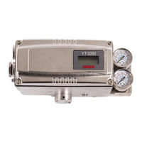
rotork YT-3302 Series Product Manual (120 pages)
SMART POSITIONER
Brand:
rotork
| Category:
Valve Positioners
| Size: 7 MB
Table of Contents
Table of Contents
2
Introduction
6
General Information for the Users
6
Manufacturer Warranty
6
Explosion Proof Warning (Only for Intrinsic Safety Type Positioners)
7
Product Description
9
General
9
Main Features and Functions
9
Label Description
10
Product Code
16
YT-3300 / 3350 Series Follows Suffix Symbols as Follows
16
YT-3303 Series Follows Suffix Symbols as Follows
18
YT-3301 / 3302 Series Follows Suffix Symbols as Follows
19
Product Specification
21
YT-3300 / 3303 / 3350 Specification
21
YT-3301 / 3302 Specification
22
Certifications
24
Parts and Assembly
27
Product Dimension
31
Installation
35
Safety
35
Tools for Installation
35
Linear Positioner Installation
36
Linear Positioner Installation of Standard Lever Type
36
3.3.1.1 Safety
37
3.3.1.2 Standard Lever Type Positioner Installation Steps
37
YT-3300L / 3350L Installation of Adapter Lever Type (on Tubeless Actuator)
42
3.3.2.1 Safety
42
3.3.2.2 Adapter Lever Type Positioner Installation Steps
43
Rotary Positioner Installation
45
YT-3300R / 3350R Components
45
YT-3303R Components
46
YT-3301R / 3302R Remote Sensor Components
46
Rotary Bracket Information (Only YT-3300R / 3350R / 3303R)
47
Rotary Positioner Installation Steps
48
Connection - Air
51
Safety
51
Supply Pressure Condition
51
Piping Condition
51
Connection - Piping with Actuator
52
Single Acting Actuator
52
Double Acting Actuator
53
Connection - Power
54
Safety
54
Connection
55
Standard Terminals
55
Terminals with Micro-Limit Switch Option
56
Terminals with Inductive Proximity Limit Switch Option
57
Terminals between Positioner Main Body and Remote Sensor of YT-3301 / 3302
58
Ground
58
Adjustments
59
Limit Switch Adjustment
59
A/M Switch Adjustment
60
Orifice Installment
61
Plate Type Orifice Installment (Except YT-3303)
61
Variable Orifice Adjustment (Only YT-3303)
61
Optional Sub-PCB Installment
62
Installation Steps
62
Maintenance
64
Supply Air
64
Seals
64
Auto Calibration and PCB Operation
65
Warning
65
LCD Display and Buttons
65
LCD Display and Symbols
65
Button and Function
66
Menu Levels
67
Run Mode (RUN)
68
Configuration and Operation
69
Calibration (Calib)
73
Acting Type (SINGLE / Double)
74
Auto Calibration 1 (AUTO 1)
74
Auto Calibration 2 (AUTO 2)
75
Auto Calibration 3 (AUTO 3)
76
Travel Zero (TVL ZERO) and Travel End (TVL End)
77
Manual Operation (man OPER)
78
Manual Operation by Set Position (man SP)
78
Manual Operation by Manipulator Value (man MV)
79
Control Parameters (CTL PARM)
80
Dead Band (Deadband)
80
Forward P Parameter (KP UP) and Reverse P Parameter (KP Dn)
81
Forward Integral Time Parameter (TI UP) and Reverse Integral Time Parameter (TI Dn)
81
Forward D Parameter (Kd UP) and Reverse D Parameter (Kd Dn)
82
GAP Parameter (GAP)
82
GAP P Parameter (GP)
83
GAP I Parameter (GI)
83
GAP D Parameter (Gd)
83
Auto Dead Band Mode (AUTO Db)
84
Performance Mode (PER)
84
Input Configuration (in CFG)
85
Signal Direction (SIG NORM / REVS)
85
Split Range Mode (SPLIT)
86
Custom Split Range Zero (CST ZERO)
86
Custom Split Range End (CST End)
87
Valve Flow Characterization Curves (CHAR)
87
User Set Characterization 5 Points (U5)
88
User Set Characterization 21 Points (U21)
89
Tight Shut Open (TSHUT OP)
90
Tight Shut Close (TSHUT CL)
91
Target Position Ramp up Rate (RAMP UP) and Target Position Ramp down Rate (RAMP Dn)
92
Output Configuration (out CFG)
94
Position Transmitter Direction (PTM NORM / REVS)
94
Position Transmitter Zero / End (PTM ZERO / End)
95
HART Feedback Direction (HT NORM / REVS)
96
Back Calculation (Backcal off / On)
97
Device Configuration (Dev CFG)
98
Action Setting (ACT REVS / Dir)
98
Linear Lever Type (LEVT Std / Adt)
98
Linear Interpolation (ITP off / On)
99
Lock of Parameters (Write Protect, W UNLOCK / LOCK)
99
Actual Position View Mode (View Mode, VI NORM / REVS)
100
Polling Address Setting (POL Addr)
100
Factory Reset (Default off / On)
101
Positioner Self-Test (SELFTEST)
102
Diagnosis Mode (Diagnd)
103
Default Alarm Settings
104
Process Status (PS)
105
Device Status (Ds)
106
View Monitoring Counts (VI CNTS)
107
Diagnostic Limit Configuration (LIMT CFG)
108
Reset Alarm Status (RST ALRM off / On)
109
View Event Log (EVT LOG)
110
Partial Stroke Test Record (View PST Result Record, PST RSLT)
111
PST Configuration (PST CFG)
112
Run PST (PST NOW)
113
Periodic PST Test (PST Schedule, PST Schd off / On)
114
Position Information (INFO)
114
Error Codes During Automatic Calibration
116
Status and Alarm Code
117
Main Software Map
119
Advertisement
Advertisement
Related Products
rotork YT-3700
rotork YT-3750
rotork YT-3100
rotork YT-3300 Series
rotork YT-3350 Series
rotork YT-3303 Series
rotork YT-3301 Series
rotork YT-3702
rotork YT-1000 Series
rotork YT-1200R
rotork Categories
Controller
Valve Positioners
Industrial Equipment
Switch
Control Unit
More rotork Manuals
Login
Sign In
OR
Sign in with Facebook
Sign in with Google
Upload manual
Upload from disk
Upload from URL