
Related Manuals for rotork YT-3400 Series


Summary of Contents for rotork YT-3400 Series
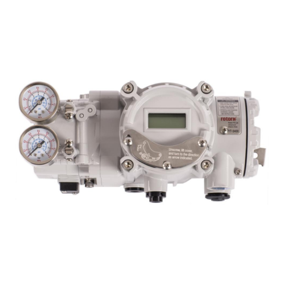
- Page 1 SMART POSITIONER PRODUCT MANUAL YT-3400 / 3450 SERIES (New NCS type) YT-3400 YT-3450 Terminal appearance Rotork YTC Limited VERSION 2.06...
-
Page 2: Table Of Contents
Smart Positioner YT-3400 / 3450 series (New NCS type) Product manual Contents Introduction ..............................6 General Information for the users ......................6 Manufacturer Warranty .........................6 Explosion Proof Warning & Specific Conditions of Use ...............7 Product Description ...........................8 General ..............................8 Main Features and Functions .......................8 Label Description ..........................9 Product Code ............................. - Page 3 Smart Positioner YT-3400 / 3450 series (New NCS type) Product manual Variable Orifice Adjustment ....................... 38 Maintenance ............................. 39 Supply air ............................39 Seals ..............................39 Auto Calibration and PCB Operation ..................... 40 Warning .............................. 40 LCD display and buttons ........................40 8.2.1 LCD display and symbols ......................
- Page 4 Smart Positioner YT-3400 / 3450 series (New NCS type) Product manual 8.9.9 Tight Shut Close (TSHUT CL) ....................... 65 8.9.10 Target Position Ramp Up Rate (RAMP UP) and Target Position Ramp Down Rate (RAMP dN) 8.9.11 Digital Input Function (dIF) ......................67 8.9.12 Digital Input Logic (dI LOGIC) ....................
- Page 5 Smart Positioner YT-3400 / 3450 series (New NCS type) Product manual Ver. 2.06...
-
Page 6: Introduction
Introduction General Information for the users Thank you for purchasing Rotork YTC Limited products. Each product has been fully inspected after its production to offer you the highest quality and reliable performance. Please read the product manual carefully prior to installing and commissioning the product. -
Page 7: Explosion Proof Warning & Specific Conditions Of Use
Smart Positioner YT-3400 / 3450 series (New NCS type) Product manual Explosion Proof Warning & Specific Conditions of Use Please ensure the unit is being used and installed in explosion proof certified environment. The positioners are Explosion proof construction for internal pressure. ➢... -
Page 8: Product Description
Smart Positioner YT-3400 / 3450 series (New NCS type) Product manual Product Description General The smart positioner accurately controls valve stroke in response to an input signal of 4 ~ 20 mA from the controller. Built-in micro-processor optimizes the positioner’s performance and provides unique functions such as Auto-Calibration, PID Control, and HART Protocol Communications. -
Page 9: Label Description
Smart Positioner YT-3400 / 3450 series (New NCS type) Product manual ➢ Polyester powder coating resists the corrosion process. (except YT-3450). ➢ Maintenance of the positioner is easy because of modularized inner structure. ➢ SIL2 certified.(For more information, see SIL Safety Instruction on homepage) Label Description •... - Page 10 Smart Positioner YT-3400 / 3450 series (New NCS type) Product manual Fig. L-2: YT-3400 metal label Fig. L-3: YT-3400 metal label (KCs) (ATEX, IECEx, NEPSI) Ver. 2.06...
- Page 11 Smart Positioner YT-3400 / 3450 series (New NCS type) Product manual Fig. L-4: YT-3400 labels (FM, CSA) Fig. L-5: YT-3450 metal label (FM, CSA) Ver. 2.06...
- Page 12 Smart Positioner YT-3400 / 3450 series (New NCS type) Product manual Fig. L-6: YT-3400, 3450 labels (EAC) Fig. L-7: YT-3450 metal label (ATEX, IECEx, KCs, NEPSI) Ver. 2.06...
- Page 13 Smart Positioner YT-3400 / 3450 series (New NCS type) Product manual Fig. L-8: YT-3400, 3450 labels (INMETRO) Ver. 2.06...
- Page 14 Smart Positioner YT-3400 / 3450 series (New NCS type) Product manual Fig. L-9: YT-3400 labels (CCC) Fig. L-10: YT-3450 metal label (CCC) Ver. 2.06...
-
Page 15: Product Code
Smart Positioner YT-3400 / 3450 series (New NCS type) Product manual Product Code YT-3400 / 3450 series follows suffix symbols as follows. YT-3400 / 3450 1 Linear Motion Type Rotary Single Acting type Double ATEX, IECEx, INMETRO, KCs, NEPSI FM, CSA Explosion Proof 10 ~ 40 mm 20 ~ 70 mm... -
Page 16: Product Specification
Smart Positioner YT-3400 / 3450 series (New NCS type) Product manual Please put the name of certificate in a purchase order. DO (Digital Output) already is included in this option, so it can’t be selected with 2 or 3 of Option together. -
Page 17: Specification Of Digital Input, Digital Output
• Current > 2.2 mA → Switching state logical "1" • Certifications ※ All certifications below are posted on Rotork YTC Limited homepage(www.ytc.co.kr). KCs (Korea) ➢ Type : Explosion proof construction for internal pressure Rating : Ex d IIC T5/T6 IP66 (YT-3400) Ex d IIC T5/T6, Ex tb IIIC T85°C/T100°C (YT-3450) - Page 18 Smart Positioner YT-3400 / 3450 series (New NCS type) Product manual IECEx ➢ Type : Explosion proof construction for internal pressure Rating : Ex db IIC T5/T6 Gb, Ex tb IIIC T85°C/T100°C Db Certification No. : IECEx EPS 11.0002X Ambient temperature : -40/-30 ~ +70°C T6(T85°C), -40/-30 ~ +80°C T5(T100°C) ➢...
-
Page 19: Parts And Assembly
Smart Positioner YT-3400 / 3450 series (New NCS type) Product manual SIL2 (in a redundant structure up to SIL 3) ➢ Intended application : Safety function is defined as to move into fail-safe-position, when signal to positioner is interrupted. Certification No. : 968/V 1155.00/20 Electromagnetic Compatibility (EMC) ➢... -
Page 20: Product Dimension
Smart Positioner YT-3400 / 3450 series (New NCS type) Product manual Product Dimension YT-3400 2.9.1 Fig. 2-2: YT-3400L (Linear type) Fig. 2-3: YT-3400R (Rotary, Fork lever type) Fig. 2-4: YT-3400R (Rotary, Namur type) Ver. 2.06... - Page 21 Smart Positioner YT-3400 / 3450 series (New NCS type) Product manual YT-3450 2.9.2 Fig. 2-5: YT-3450L (Linear type) Fig. 2-6: YT-3450R (Rotary, Fork lever type) Fig. 2-7: YT-3450R (Rotary, Namur type) Ver. 2.06...
-
Page 22: Installation
Smart Positioner YT-3400 / 3450 series (New NCS type) Product manual Installation Safety When installing a positioner, please ensure to read and follow safety instructions. ➢ Any input or supply pressures to valve, actuator, and / or to other related devices must be turned off. -
Page 23: Tools For Installation
Smart Positioner YT-3400 / 3450 series (New NCS type) Product manual Tools for installation ➢ Hex key set for hex socket cap bolts ➢ (+) & (-) Screw drivers ➢ Spanners for hexagonal-head bolts Linear positioner Installation Linear positioner should be installed on linear motion valves such as globe or gate type which uses spring return type diaphragm or piston actuators. -
Page 24: Positioner Installation Steps
Smart Positioner YT-3400 / 3450 series (New NCS type) Product manual Positioner Installation Steps 3.3.2 1) Assemble the positioner with the bracket made in previous step by fastening the bolts. The bolt size is M8 x 1.25P. Fig. 3-4: Attaching the positioner to bracket Fig. - Page 25 Smart Positioner YT-3400 / 3450 series (New NCS type) Product manual 5) Insert the connection bar between the feedback lever and lever spring. The connection bar must be located upward from the lever spring as shown the below left figure. If it is located downward from the lever spring as shown the below right figure, the connection bar or the lever spring will be worn out quickly because of excessive strong tension.
- Page 26 Smart Positioner YT-3400 / 3450 series (New NCS type) Product manual ※ The effective linear lever angle is 30 degree. Stroke : 30 mm Stroke : 70 mm Fig. 3-9: Feedback lever and location of the connection bar 8) After installing the positioner, operate the valve from 0 % to 100 % stroke by using direct air to the actuator.
-
Page 27: Rotary Positioner Installation
Smart Positioner YT-3400 / 3450 series (New NCS type) Product manual Rotary positioner Installation Rotary positioner should be installed on rotary motion valve such as ball or butterfly type which uses rack and pinion, scotch yoke or other type of actuators which its stem rotates 90 degrees. Before proceeding with the installation, ensure following components are available. -
Page 28: Rotary Bracket Information
Smart Positioner YT-3400 / 3450 series (New NCS type) Product manual Rotary Bracket Information 3.4.2 The rotary bracket set (included with the positioner) contains two components. The bracket is designed to fit onto the actuator with 20 mm, 30 mm and 50 mm stem height (H) according to VDI/VDE 3845 standard. -
Page 29: Rotary Positioner Installation Steps
Smart Positioner YT-3400 / 3450 series (New NCS type) Product manual Fig. 3-14: Actuator stem Height Fig. 3-15: Exploded Brackets 3.4.3 Rotary positioner Installation Steps 1) Please check the actuator’s stem height and adjust the brackets by referring to the above bracket table. - Page 30 Smart Positioner YT-3400 / 3450 series (New NCS type) Product manual 5) (Only Fork lever type) After setting fork lever position, fasten lock nuts which are located on the bottom of the fork lever. Ensure to set the gap between the top of upper bracket and the top of the fork lever within 6 ~ 11 mm.
-
Page 31: Connection - Air
Supply pressure should be clean and dry air – avoiding moisture, oil and dust. ➢ Always recommended to use air filter regulator (i.e. YT-200 series). Rotork YTC Limited has not tested positioner’s operation with any other gases other than ➢ clean air. Please contact Rotork YTC Limited for any questions. -
Page 32: Connection - Piping With Actuator
Smart Positioner YT-3400 / 3450 series (New NCS type) Product manual Connection – Piping with actuator Single acting actuator 4.4.1 Singe acting type positioner is set to use only OUT1 port. OUT1 port of positioner should be connected to supply port of actuator when using spring return actuator of single acting type. Fig. -
Page 33: Connection - Power
Smart Positioner YT-3400 / 3450 series (New NCS type) Product manual Connection – Power Safety ➢ There are two conduit entries on the product. See “2.4 Product Code” for conduit entry threads. ➢ When installing in hazardous and explosive gas area, conduit tube or pressure-proof packing union must be used. -
Page 34: Terminal Overview
Smart Positioner YT-3400 / 3450 series (New NCS type) Product manual Terminal overview 1) Open terminal cover by loosening a locking socket set screw using 2 mm hex wrench. 2) Insert signal cables with ring terminals into the conduit entry and secure them on the terminals of the block by tightening bolts with 1.5 N •... - Page 35 Smart Positioner YT-3400 / 3450 series (New NCS type) Product manual Fig. 5-4: Terminal Overview 2 (DO1, DO2, DI) Ver. 2.06...
- Page 36 Smart Positioner YT-3400 / 3450 series (New NCS type) Product manual Terminal name Signal name Function Apply analog current command 4 ~ 20mA to this IN +, IN ‒ Current input signal (+), (‒) terminal to supply power and signal to the positioner. Safety ground Safety ground Analog feedback signal indicating the position of the...
-
Page 37: Ground
Smart Positioner YT-3400 / 3450 series (New NCS type) Product manual Ground 5.2.1 1) Ground must be done before operating the positioner. 2) There are three ground bolts at the positioner. Open terminal cover and there are two internal ground bolts on the left inside of housing and on the left of terminal plate. When using internal ground, use 2 mm hex wrench to loosen a socket set screw of of the terminal box cover. -
Page 38: Adjustments
Smart Positioner YT-3400 / 3450 series (New NCS type) Product manual Adjustments A/M switch adjustment 1) On the left hand bottom of positioner, there is A/M switch (Auto/Manual). If the switch is turned clockwise (toward “A”) and fastened tightly, then the supply pressure will be transferred to actuator through outport by positioner control. -
Page 39: Maintenance
Smart Positioner YT-3400 / 3450 series (New NCS type) Product manual Maintenance Supply air If Supply air pressure is not stable or Supply air is not clean, the positioner may not function properly. Air quality and pressure should be checked regularly to see if the air is clean and pressure set is normal. Seals it is recommended to check if there are any damaged parts of the positioner once a year. -
Page 40: Auto Calibration And Pcb Operation
Smart Positioner YT-3400 / 3450 series (New NCS type) Product manual Auto Calibration and PCB Operation Warning Following process will operate valve and actuator. Before proceeding with any Auto Calibration, please separate valve from the entire system by using bypass valve, so Auto Calibration will not affect entire valve process. -
Page 41: Button And Function
Smart Positioner YT-3400 / 3450 series (New NCS type) Product manual Button and function 8.2.2 Positioner has 4 buttons that perform various functions. Fig 8-2 Buttons Function Used to navigate to each menu at the same level or to increase the value of the selected parameter. (UP) Used to navigate to each menu at the same level in reverse −... -
Page 42: Menu Levels
Smart Positioner YT-3400 / 3450 series (New NCS type) Product manual Menu levels The basic menu structure consists of the RUN Mode Monitor and the Configuration/Operation. The Run Mode Monitor menu allows you to monitor the values of various variables. The Configuration/Operation menu provides calibration and tuning, manual operation, configuration of I/O port function, configuration and self-test of positioner, configuration of diagnostic function, and basic information of the positioner. -
Page 43: Run Mode (Run)
Smart Positioner YT-3400 / 3450 series (New NCS type) Product manual Run Mode (RUN) The RUN Mode Monitor is displayed on the LCD display when power is provided to the positioner. Pressing the UP/DOWN button scrolls through the various process variables shown in table below. -
Page 44: Configuration And Operation
Smart Positioner YT-3400 / 3450 series (New NCS type) Product manual Configuration and Operation The Table below shows the eight Configuration/Operation menus, each submenu, ranges for each parameter, and initial factory settings. The words shown in [ ] for each menu represent the abbreviations of each word displayed when operating the LCD screen. - Page 45 Smart Positioner YT-3400 / 3450 series (New NCS type) Product manual Level 1 Level 2 Range Initial factory setting Linear, Quick Open, Equal Percent, User Set Characterization [CHAR] 5point, User Set 21point [LIN, QO, EQ, U5, U21] User Set Characterization 5p 0 %, 25 %, 50 %, 75 %, 0 ~ 110 [%] [USER 5P]...
- Page 46 Smart Positioner YT-3400 / 3450 series (New NCS type) Product manual Level 1 Level 2 Range Initial factory setting Write Protect [W] [UNLOCK, LOCK] UNLOCK View Mode [VI] [NORM, REVS] NORM Device Configuration Polling Address [POL AddR] [0 ~ 63] [dEV CFG] Factory Reset [dEFAULT] Self-Test [SELFTEST]...
- Page 47 Smart Positioner YT-3400 / 3450 series (New NCS type) Product manual Level 1 Level 2 Range Initial factory setting Position Sensor Type [PSNT] PTN, NCS Absolute Position in Angle ***.* ° Information [INFO] [AbS ANGL] HART Protocol Revision [HART VER] The Table below identifies the range and initial factory settings of each parameter for Menu Level 2 and Menu Level 3 where the menu hierarchy has been lowered by one level.
- Page 48 Smart Positioner YT-3400 / 3450 series (New NCS type) Product manual Level 2 Level 3 Range Initial factory setting PST Ramp Up Rate oFF, 1 ~ 100 [%/sec] [PRAMP UP] PST Ramp Down Rate oFF, 1 ~ 100 [%/sec] PST CFG [PRAMP dN] oFF, PST Time Remaining...
-
Page 49: Calibration (Calib)
Smart Positioner YT-3400 / 3450 series (New NCS type) Product manual Calibration (CALIb) The calibration consists of five menus. Acting Type Set manually single or double acting by actuator type [SINGLE/ dOUbLE] Auto Calibration 1 [AUTO 1] Calibration on the zero and end points of the valve Calibration [CALIb] Auto Calibration 2 [AUTO 2]... -
Page 50: Auto Calibration 1 (Auto 1)
Smart Positioner YT-3400 / 3450 series (New NCS type) Product manual Auto Calibration 1 (AUTO 1) 8.6.2 AUTO 1 is used to set only the origin and end points. It does not change the PID and other parameter values that already have been set. This is usually used when the origin and end points of the already calibrated positioner have changed slightly. -
Page 51: Travel Zero (Tvl Zero) And Travel End (Tvl End)
Smart Positioner YT-3400 / 3450 series (New NCS type) Product manual Travel Zero (TVL ZERO) and Travel end (TVL ENd) 8.6.4 This is a manual adjustment of the zero point or endpoint of the valve after auto calibration. Once you enter the TVL ZERO (or TVL ENd) setting, press the UP/DOWN button to change the zero point (or endpoint) of the valve, and then press the ENTER button to save it. -
Page 52: Manual Operation (Man Oper)
Smart Positioner YT-3400 / 3450 series (New NCS type) Product manual Manual Operation (MAN OPER) It is used to manually raise or lower the valve stem by operating the <+> or <-> buttons. This can be used to observe the move of valve stem without any external input signals. When engaged, the current input signal to the positioner has no effect on the positioner. -
Page 53: Manual Operation By Manipulator Value (Man Mv)
Smart Positioner YT-3400 / 3450 series (New NCS type) Product manual Manual Operation by Manipulator Value (MAN MV) 8.7.2 The input to I/P converter is incremented or decremented by the <+> and <-> buttons based on the currently entered I/P input value, which moves the stem of the valve up and down. Once out of the menu by <ESC>, the positioner is controlled again by an input signal. -
Page 54: Control Parameters (Ctl Parm)
Smart Positioner YT-3400 / 3450 series (New NCS type) Product manual Control Parameters (CTL PARM) Followings are the values changeable at the Control Parameters Mode. 1) Dead Band (dEAdbANd) 2) Forward P parameter (KP UP) and reverse P parameter (KP dN) 3) Forward Integral time parameter (TI UP) and reverse Integral time parameter (TI dN) 4) Forward D parameter (Kd UP) and reverse D parameter (Kd dN) 5) GAP Parameter (GAP) -
Page 55: Forward P Parameter (Kp Up) And Reverse P Parameter (Kp Dn)
Smart Positioner YT-3400 / 3450 series (New NCS type) Product manual Forward P parameter (KP UP) and reverse P parameter (KP dN) 8.8.2 The KP parameter is the proportional control constant to the calibration signal to reduce the error between the target position and the current position, the KP UP is applied when the valve moves in the direction of increasing output air pressure, and KP dN is applied when the valve moves in the direction of venting output air pressure. -
Page 56: Forward D Parameter (Kd Up) And Reverse D Parameter (Kd Dn)
Smart Positioner YT-3400 / 3450 series (New NCS type) Product manual Forward D parameter (Kd UP) and reverse D parameter (Kd dN) 8.8.4 The Kd parameter is a differential value that adds the correction signal due to the rate of error to the existing calibration signal. -
Page 57: Gap P Parameter (Gp)
Smart Positioner YT-3400 / 3450 series (New NCS type) Product manual GAP P parameter (GP) 8.8.6 GP is a proportional gain. If the valve position is within the GAP parameter range, a proportion gain created based on KP and GP is applied to valve control. 3 seconds →... -
Page 58: Auto Dead Band Mode (Auto Db)
Smart Positioner YT-3400 / 3450 series (New NCS type) Product manual Auto Dead band Mode (AUTO db) 8.8.9 This function is used to suppress a hunting for valves with high static friction. The initial value is OFF and it shall be set to 0 % to activate the auto dead band automatically. The value is changed to a proper value once this mode is activated. -
Page 59: Input Configuration (In Cfg)
Smart Positioner YT-3400 / 3450 series (New NCS type) Product manual Input Configuration (IN CFG) Followings are the values changeable at the Input Configuration Mode. 1) Signal Direction (SIG NORM / REVS) 2) Split Range Mode (SPLIT) 3) Custom Split Range Zero (CST ZERO) 4) Custom Split Range End (CST ENd) 5) Characterization Curves (CHAR) 6) User Set Characterization 5 Points (U5) -
Page 60: Split Range Mode (Split)
Smart Positioner YT-3400 / 3450 series (New NCS type) Product manual Split Range Mode (SPLIT) 8.9.2 This is used to set the range of the input signal to control the entire stroke of the valve. You can select one of the four input signals that consists of 4 ~ 20 mA, 4 ~ 12 mA, 12 ~ 20 mA, and user settings (Custom, CSt). -
Page 61: Custom Split Range End (Cst End)
Smart Positioner YT-3400 / 3450 series (New NCS type) Product manual Custom Split Range End (CST ENd) 8.9.4 It is used to set the current corresponding to the endpoint when the valve position of 0 to 100 % is controlled by the user-set CUSTOM. For example, if the valve is controlled by 4 ~ 18 mA instead of 4 ~ 20 mA, CST ENd is 18 mA. -
Page 62: User Set Characterization 5 Points (U5)
Smart Positioner YT-3400 / 3450 series (New NCS type) Product manual User Set Characterization 5 Points (U5) 8.9.6 A total of 5 target positions are set every 4 mA intervals. When shipped from the factory, the initial positions are P0 (4 mA, 0 %), P1 (8 mA, 25 %), P2 (12 mA, 50 %), P3 (16 mA, 75 %), and P4 (20 mA, 100 %). -
Page 63: User Set Characterization 21 Points (U21)
Smart Positioner YT-3400 / 3450 series (New NCS type) Product manual User Set Characterization 21 Points (U21) 8.9.7 A total of 21 target points can be set every 0.8 mA intervals. When shipped from the factory, the initial P0 (4 mA, 0 %), P1 (4.8 mA, 5 %), P2 (5.6 mA 10 %), - - -, P19 (19.2 mA, 95 %), and P20 (20 mA, 100 %). -
Page 64: Tight Shut Open (Tshut Op)
Smart Positioner YT-3400 / 3450 series (New NCS type) Product manual Tight Shut Open (TSHUT OP) 8.9.8 It is used to ensure that the valve is fully opened with a large force. When the input signal SP is greater than the value set in the TSHUT OP, all available force is applied to OUT 1 port to tightly open the valve. - Page 65 Smart Positioner YT-3400 / 3450 series (New NCS type) Product manual Tight Shut Close (TSHUT CL) 8.9.9 It is used to ensure that the valve is fully closed with a large force. When the input signal SP is smaller than the value set in the TSHUT CL, air pressure is vented through OUT 1 port to tightly close the valve.
-
Page 66: Target Position Ramp Up Rate (Ramp Up) And Target Position Ramp Down Rate (Ramp Dn)
Smart Positioner YT-3400 / 3450 series (New NCS type) Product manual Target Position Ramp Up Rate (RAMP UP) and Target Position Ramp Down Rate (RAMP dN) 8.9.10 It is used to prevent the valve from moving too fast when the process to be controlled is too sensitive to rapid changes in flow or pressure. -
Page 67: Digital Input Function (Dif)
Smart Positioner YT-3400 / 3450 series (New NCS type) Product manual 3 seconds → → → Press <+> or Press <+> or <-> button <-> button if the above is not if the above is not displayed. displayed. <+>/<-> <-> <ESC>... -
Page 68: Digital Input Logic (Di Logic)
Smart Positioner YT-3400 / 3450 series (New NCS type) Product manual Digital Input Logic (dI LOGIC) 8.9.12 (Applicable to Communication “5” of Product Code) It sets the logic that activates digital input to High (HI) or Low (Lo). The initial factory setting is HI, which means that when 11 ~ 28 V DC voltage is applied, it is recognized as HI state. -
Page 69: Output Configuration (Out Cfg)
Smart Positioner YT-3400 / 3450 series (New NCS type) Product manual Output Configuration (OUT CFG) 8.10 Followings are the values changeable at the Output Configuration Mode. 1) Position Transmitter Direction (PTM NORM / REVS) 2) Position Transmitter Zero / End (PTM ZERO / ENd) 3) HART Feedback Direction (HT NORM / REVS) 4) Back Calculation (bACKCAL oFF / on) 5) Limit Switch Mode (LS MOdE oFF/ on), (This function is available when either... -
Page 70: Position Transmitter Zero / End (Ptm Zero / End)
Smart Positioner YT-3400 / 3450 series (New NCS type) Product manual Position Transmitter Zero / End (PTM ZERO / ENd) 8.10.2 ZERO adjusts the zero point of the position transmitter (4 mA feedback), and ENd adjusts the end point of the transmitter (20 mA feedback). This is used when the analog output signal needs to be feedbacked differently than the actual position of the valve, or to be adjusted a little. -
Page 71: Hart Feedback Direction (Ht Norm / Revs)
Smart Positioner YT-3400 / 3450 series (New NCS type) Product manual <+>/<-> 3 seconds → → → Press <+> or Adjusting zero The actuator <-> button point. moves to if the above is not Press <+> or zero point. <-> button displayed. -
Page 72: Back Calculation (Backcal Off / On)
Smart Positioner YT-3400 / 3450 series (New NCS type) Product manual Back Calculation (bACKCAL oFF / on) 8.10.4 This function recalculates the output "RUN AP" value changed by the flow characteristics setting mode to display it linearly proportional to actual input current. For example, if the flow characteristic mode is set from "LIN"... - Page 73 Smart Positioner YT-3400 / 3450 series (New NCS type) Product manual Note. Menu flow related to Limit Switch Menu name Description It is used to set the logic that determines the state of the Digital Output switch to High(HI) or Low(Lo) when the valve dO1LOGIC reaches Limit High or Limit Low position.
-
Page 74: Digital Output Function 0 / 1 (Do1 / Do2)
Smart Positioner YT-3400 / 3450 series (New NCS type) Product manual Digital Output Function 0 / 1 (dO1 / dO2) 8.10.6 This is used to output a specific alarm through the digital output port when triggered. Any of the alarms below can be configured to activate digital output. -
Page 75: Digital Output 1 Logic / Digital Output 2 Logic (Do1 Logic Hi / Lo, Do2 Logic Hi / Lo)
Smart Positioner YT-3400 / 3450 series (New NCS type) Product manual 3 seconds → → → Press <+> or Press <+> or <-> button <-> button if the above is not if the above is not displayed. displayed. <+>/<-> <ESC> 3 times →... -
Page 76: Analog Output Function (Aof)
Smart Positioner YT-3400 / 3450 series (New NCS type) Product manual Analog Output Function (AOF) 8.10.8 ((This function is available when both 6 Communication “5” and Output Option “1” or “3” of Product code are selected simultaneously.) This is used to output a specific alarm (NAMUR NE43) through the analog output port when triggered. If one of the alarms below occurs, it can be configured so that the analog output is activated. -
Page 77: Analog Output Logic (Ao Logic Lo / Hi)
Smart Positioner YT-3400 / 3450 series (New NCS type) Product manual 3 seconds → → → Press <+> or Press <+> or <-> button <-> button if the above is not if the above is not displayed. displayed. <+>/<-> <ESC> 3 times →... -
Page 78: Device Configuration (Dev Cfg)
Smart Positioner YT-3400 / 3450 series (New NCS type) Product manual Device Configuration (dEV CFG) 8.11 Followings are the values changeable at the dEV CFG Mode. 1) Action Setting (ACT REVS / dIR) 2) Linear Lever Type (STd / AdT) 3) Linear Interpolation (ITP oFF / on) 4) Lock of Parameters (Write Protect, W UNLOCK / LOCK) 5) Actual Position View Mode (View Mode, VI NORM / REVS) -
Page 79: Linear Interpolation (Itp Off / On)
Smart Positioner YT-3400 / 3450 series (New NCS type) Product manual Linear Interpolation (ITP oFF / on) 8.11.3 ITP is used to compensate the linear motion of the actuator into rotary motion of the feedback lever. Following Auto Calibration, the ITP mode is set automatically to “on” when the angle range of the feedback lever is greater than 20 °, but it is set to oFF when this angle is less than 20 °... -
Page 80: Actual Position View Mode (View Mode, Vi Norm / Revs)
Smart Positioner YT-3400 / 3450 series (New NCS type) Product manual Actual Position View Mode (View Mode, VI NORM / REVS) 8.11.5 This function is used to set the "RUN AP" value on the LCD to be displayed as direct (NORM) or reversely (REVS) as the actual position of the valve. -
Page 81: Factory Reset (Default Off / On)
Smart Positioner YT-3400 / 3450 series (New NCS type) Product manual Factory Reset (dEFAULT oFF / on) 8.11.7 This function initializes all parameters stored in the positioner to initial factory setting. In the dEFAULT mode, press the Enter button to enables ON/OFF setting and then pressing Enter button for approximately 3 seconds changes the dEFAULT mode from oFF to “on". -
Page 82: Positioner Self-Test (Selftest)
Smart Positioner YT-3400 / 3450 series (New NCS type) Product manual Positioner Self-Test (SELFTEST) 8.11.8 This function is used to diagnose the operation of the memory (RAM or NVM) inside the positioner. If no error is found during SELFTEST, the SELFTEST menu is displayed after FINISH is displayed, and if abnormalities are detected, the message "SEt / NVMW"... -
Page 83: Diagnosis Mode (Diagnd)
Smart Positioner YT-3400 / 3450 series (New NCS type) Product manual Diagnosis Mode (dIAGNd) 8.12 Followings are the values changeable at the dIAGNO Mode. 1) Default Alarm Settings (Some functions are applicable to Communication only “5” of Product Code) 2) Process Status (PS) 3) Device Status (dS) 4) View Monitoring Counts (VI CNTS) 5) Diagnostic Limit Configuration (LIMT CFG) - Page 84 Smart Positioner YT-3400 / 3450 series (New NCS type) Product manual Default setting Resettable manually? Communication Status / Alarm Default NE107 signal when alarm occurred? 0 or 2 Local Operation Active Enable Enable Functional Check Auto Calibration Running Enable Enable Functional Check PST Running Enable...
-
Page 85: Process Status (Ps)
Smart Positioner YT-3400 / 3450 series (New NCS type) Product manual Default setting Resettable manually? Status / Alarm Communication Default NE107 signal when alarm occurred? 0 or 2 DI Status Change + Disable Enable Not defined DO1 Status Change + Disable Enable Not defined... -
Page 86: Device Status (Ds)
Smart Positioner YT-3400 / 3450 series (New NCS type) Product manual Process Alarm Abbreviation Cycle Count Limit CYCC Travel Accumulator Limit TVLA Operating Count Limit OPRC Temperature High Limit TMPH Temperature Low Limit TMPL Travel High Limit TVLH Travel Low Limit TVLL Deviation Timeout dVTO... - Page 87 Smart Positioner YT-3400 / 3450 series (New NCS type) Product manual Reassignment of NE107 signals to device alarms shall be made using HART communication. The table below shows the type of the device status or alarm and its abbreviations. See 8.15 Status and Alarm Code for the details of each alarm.
-
Page 88: View Monitoring Counts (Vi Cnts)
Smart Positioner YT-3400 / 3450 series (New NCS type) Product manual View Monitoring Counts (VI CNTS) 8.12.4 It is used to view the accumulated data information for valve movement up to now. Counter Name Abbreviation [unit] Function The accumulated number of times the valve has changed its Cycle Count CYCL CNT direction. -
Page 89: Diagnostic Limit Configuration (Limt Cfg)
Smart Positioner YT-3400 / 3450 series (New NCS type) Product manual Diagnostic Limit Configuration (LIMT CFG) 8.12.5 This configuration is used to set the upper or lower limit that is generated by the Travel High Limit Alarm, Travel Low Limit Alarm, Temperature High Limit Alarm, Temperature Low Limit Alarm, and Deviation Timeout Alarm. -
Page 90: Reset Alarm Status (Rst Alrm Off / On)
Smart Positioner YT-3400 / 3450 series (New NCS type) Product manual Reset Alarm Status (RST ALRM oFF / on) 8.12.6 The alarm is automatically released when the cause of the alarm is removed. For example, if a high- temperature alarm is created, the alarm is automatically released when internal temperature drops below the Temperature High Limit. -
Page 91: View Event Log (Evt Log)
Smart Positioner YT-3400 / 3450 series (New NCS type) Product manual View Event Log (EVT LOG) 8.12.7 This is used to show the 20 most recent events that occurred in operation. Record 0 is the most recent of the 20 events and Record 19 is the oldest event. The event detail shows the time when the event occurred (EVT TIME) as well as the content of the event (EVT INFO). -
Page 92: Partial Stroke Test Record (View Pst Result Record, Pst Rslt)
Smart Positioner YT-3400 / 3450 series (New NCS type) Product manual Partial Stroke Test Record (View PST Result Record, PST RSLT) 8.12.8 This is used to show information about the 10 most recent Partial Stroke Tests performed. Record 1 is the most recent of the 10 PST histories, and Record 10 is the result of the oldest PST operation. -
Page 93: Pst Configuration (Pst Cfg)
Smart Positioner YT-3400 / 3450 series (New NCS type) Product manual PST Configuration (PST CFG) 8.12.9 Parameter names Abbreviation [unit] Description Sets time interval PST is triggered. Initial factory setting PST Interval INTERVAL [days] is 365 days. Sets the start position to launch PST. Initial factory setting PST Start Position START PO [%] is 100 %. -
Page 94: Run Pst (Pst Now)
Smart Positioner YT-3400 / 3450 series (New NCS type) Product manual 3 seconds → → → Press <+> or Press <+> or <-> button <-> button if the above is not if the above is not displayed. displayed. <+>/<-> <ESC> 4 times →... -
Page 95: Periodic Pst Test (Pst Schedule, Pst Schd Off / On)
Smart Positioner YT-3400 / 3450 series (New NCS type) Product manual 8.12.11 Periodic PST Test (PST Schedule, PST SCHd oFF / on) When PST SCHd is set to ON, the Partial Stroke Test is executed regularly under the conditions set in 8.12.9 above. - Page 96 Smart Positioner YT-3400 / 3450 series (New NCS type) Product manual LCD display Description YT3400L Model Name Software Version [SOFT VER] “4.0.00” Software Input date : “2022-01(JA)-31” 4.0.00 (January JA, February FB, March MR, April AR, May MY, June JN, July JL, SOFT VER August AG, September SP, October OT, November NV, December DC) 2022JA31...
-
Page 97: Error Codes During Automatic Calibration
Smart Positioner YT-3400 / 3450 series (New NCS type) Product manual Error codes during automatic calibration 8.14 There may be an error during the automatic calibration in case of irregularity. ➢ Error code : indicated if the positioner is out of control, malfunctions or becomes imprecise. ➢... -
Page 98: Status And Alarm Code
Smart Positioner YT-3400 / 3450 series (New NCS type) Product manual Status and Alarm Code 8.15 Refer to the table below to check the status and alarm codes that can be displayed on LCD screen or HART monitor, and then take the appropriate action. Note 1. - Page 99 Smart Positioner YT-3400 / 3450 series (New NCS type) Product manual Alarm Abbreviation Status / Alarm name Description or proposed actions Code It is active if internal temperature exceeds Temperature Hi Limit. If the set temperature exceeds the maximum TMPH + Temperature Hi Limit temperature allowed by the product, the product may not operate if the ambient temperature around the positioner is...
- Page 100 Smart Positioner YT-3400 / 3450 series (New NCS type) Product manual Alarm Abbreviation Status / Alarm name Description or proposed actions Code It is active when the travel exceeds the available high stroke of the valve/actuator. The available stroke is already TVCH Travel Cutoff Hi Limit set during auto calibration.
- Page 101 Smart Positioner YT-3400 / 3450 series (New NCS type) Product manual Alarm Abbreviation Status / Alarm name Description or proposed actions Code It is active when more than one of alarms assigned to “Failure” have happened. Remove the cause of the alarm FAIL ++ Failure after checking it.
-
Page 102: Main Software Map
Smart Positioner YT-3400 / 3450 series (New NCS type) Product manual Main Software Map Ver. 2.06... - Page 103 Product manual Manufacturer: Rotork YTC Limited Address: 81, Hwanggeum-ro, 89 Beon-gil, Yangchon-eup, Gimpo-si, Gyeonggi-do, South Korea Postal code: 10048 Tel: +82-31-986-8545 Fax: +82-70-4170-4927 Email: ytc.sales@rotork.com Homepage : http://www.ytc.co.kr Issued : 2022-01-20 Copyright © Rotork YTC Limited. All Rights Reserved. Ver. 2.06...
Need help?
Do you have a question about the YT-3400 Series and is the answer not in the manual?
Questions and answers