Table of Contents
Advertisement
Quick Links
Advertisement
Table of Contents

Related Manuals for TP-Link VIGI NVR2016H


Summary of Contents for TP-Link VIGI NVR2016H
- Page 1 Installation Guide Network Video Recorder...
-
Page 2: Table Of Contents
Contents Chapter 1 Appearance ——————————— 3 Front Panel ..............3 Rear Panel ...............4 Chapter 2 Installation ——————————— 7 Package Contents ..........7 Safety Precautions ..........7 Installation Tools ...........10 Hard Drive Installation ........10 Product Installation ..........12 Chapter 3 Hardware Connection —————— 14 Chapter 4 Configuration —————————— 15 Appendix FAQ ———————————————... -
Page 3: Chapter 1 Appearance
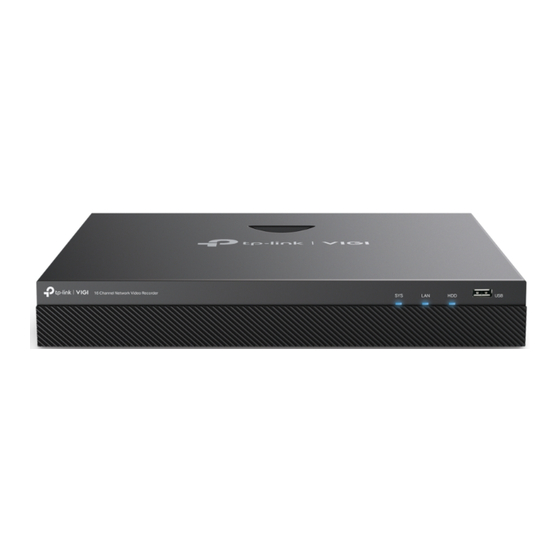
The figure is for demonstration purposes only. Your device may differ in appearance from the depicted. VIGI NVR2016H ■ The front panel of VIGI NVR2016H is shown as the following figure. Indication On: System is running normally. Off: System is running abnormally. -
Page 4: Rear Panel
The figure is for demonstration purposes only. Your device may differ in appearance from the depicted. VIGI NVR2016H ■ The rear panel of VIGI NVR2016H is shown as the following figure. Grounding Terminal The device comes with lightning protection mechanism. Power Socket Connect the female connector of the power cord here, and the male connector to the AC power outlet. - Page 5 Secure the lock (not provided) into the security slot to prevent the device from being stolen. VIGI NVR2016H-16P/VIGI NVR2016H-16MP ■ The rear panel of VIGI NVR2016H-16P/VIGI NVR2016H-16MP is shown as the following figure. Grounding Terminal The device comes with lightning protection mechanism.
- Page 6 50/60 Hz). USB Port Connect to additional devices such as USB mouse, USB storage device, and USB keyboard. eSATA Connect to external hard drive. HDMI Output port for high-definition audio and video signals. Connect your monitor to this port if it uses HDMI connection. Output port for analog video signals.
-
Page 7: Chapter 2 Installation
Chapter 2 Installation Package Contents Make sure that the package contains the following items. Please contact your distributor, if any of the listed items is damaged or missing. The figures are for demonstration only. The actual items may differ in appearance and quantity from the depicted. - Page 8 Place the device with its bottom surface downward. ■ Site Requirements ■ Temperature/Humidity Keep the equipment room at an appropriate level of temperature and humidity. Too much or too little humidity may lead to bad insulation, leakage of electricity, mechanical property changes, and corrosion. High temperatures may accelerate aging of the insulation materials, significantly shortening the service life of the device.
- Page 9 Use the signal SPD (Surge Protective Device) when wiring outdoor. ■ Note: For detailed lightning protection measures, go to https://www.tp-link.com/ support, search the model number of your product and go to the product Support web page, refer to the Lightning Protection Guide from the Related Documents: https://www.tp-link.com/us/configuration-guides/lightning_protection_guide/.
-
Page 10: Installation Tools
The rack or workbench is flat, stable, and sturdy enough to support the ■ weight of 5.5 kg at least. The rack or workbench has a good ventilation system. The equipment ■ room is well ventilated. The rack is well grounded. Keep the device less than 1.5 meters away ■... - Page 11 3. Match the screws on the HDD with the holes on the NVR. Here we take 3.5-inch HDD as an example. Up to 2 HDDs can be mounted at a time. 4. Connect one end of the power cable and data cable to the hard drive, and the other end to the NVR.
-
Page 12: Product Installation
5. Replace the cover and fasten the screws of the NVR. Product Installation Desktop Installation ■ To install the device on the desktop, follow the steps: 1. Set the device on a flat surface which is strong enough to support the entire weight of the device with all fittings. - Page 13 Rack Installation ■ To install the device in an EIA standard-sized, 19-inch rack, follow the instructions described below: 1. Check the efficiency of the grounding system and the stability of the rack. 2. Secure the supplied rack-mounting brackets to each side of the device with supplied screws, as illustrated in the following figure.
-
Page 14: Chapter 3 Hardware Connection
Chapter 3 Hardware Connection Follow the steps below to complete the hardware connection. *Only PoE NVRs have PoE ports to power PoE IPCs. Mouse PoE IPCs Network Device (e.g. Router, Switch) Monitor 1. Connect your monitor to the HDMI or VGA port according to the connection port it supports. -
Page 15: Chapter 4 Configuration
Chapter 4 Configuration NVR can add and manage cameras in batches. * Here we use TP-Link cameras as an example. For other camera brands, please refer to their User Manuals to add the cameras. Step 1. Connect your cameras to the same network as your NVR. - Page 16 Remotely view live video, manage NVR, and get instant alerts. 1. Download and install the latest TP-Link VIGI app. 2. Open the app and log in with your TP-Link ID. If you don’t have an account, sign up first. 3. Tap the + button on the top right and follow the app instructions to add your NVR.
- Page 17 View live video and modify NVR settings on your computer. 1. Download the VIGI Security Manager on your computer at https:// www.tp-link.com/support/download/vigi-security-manager/. 2. Install the VIGI Security Manager and open it. 3. NVR on the same network as your computer can be automatically discovered.
- Page 18 2. Make sure your NVR is in the same network segment as your network devices, or select Auto as the mode to configure the NVR to obtain a dynamic IP address. For more details, please refer to the NVR’s User Guide. If you have more questions, please visit https://www.tp-link.com/support/ faq/2850/.
- Page 19 Do not leave a battery subjected to extremely low air pressure that may result in an explosion or the leakage of flammable liquid or gas. EU Declaration of Conformity TP-Link hereby declares that the device is in compliance with the essential requirements and other relevant provisions of directives 2014/30/EU, 2014/35/EU, 2009/125/EC, 2011/65/EU and (EU)2015/863.
- Page 20 UK Declaration of Conformity TP-Link hereby declares that the device is in compliance with the essential requirements and other relevant provisions of the Electromagnetic Compatibility Regulations 2016 and Electrical Equipment (Safety) Regulations 2016. The original UK Declaration of Conformity may be found at https://www.tp-link.com/support/...
Need help?
Do you have a question about the VIGI NVR2016H and is the answer not in the manual?
Questions and answers