
Related Manuals for MessKonzept FTC320 Ex


Summary of Contents for MessKonzept FTC320 Ex
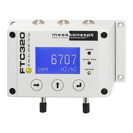
- Page 1 Operating Manual FTC320 Ex Gas analysis using thermal conductivity measurement for zone 2 ATEX II 3G Ex nR IIC T4 Gc...
- Page 2 All information of technical nature and particulars of the product and its use (including the information in this manual) are given by Messkonzept in good faith. However, it is acknowledged that there may be errors or omissions in this manual. Images and drawings may not be in scale. For the latest revisions to this manual contact Messkonzept or visit www.messkonzept.de.
- Page 3 Page 2 of 47 Quick Installation Guide For quick installation of the FTC320 we recommend reading the following chapters of this manual: • Chapter 1 "Operator Safety": Important warnings, safety instructions and intended use. • Chapter 3 "Assembly of the Instrument": Mounting, pneumatic and electric connection. Also see Chapter 10 "Appendix: Dimensional Drawing"...
-
Page 4: Table Of Contents
Page 3 of 47 Contents 1 Operator Safety 1.1 Notes on Safety Conventions and Icons ......1.2 Safety instructions for use in explosion hazard areas Zone 2 . - Page 5 Page 4 of 47 6.4.1 Current Output Setup ....... . . 23 6.4.2 Voltage Output Setup .
-
Page 6: Operator Safety
• Make sure that the electric installation protection against accidental contact adheres to the applicable safety regulations. • Pay regard to the local regulations and circumstances regarding electrical installa- tions. • Repairs should only be carried out by Messkonzept. File name: FTC320Ex Operating Manual_1.09KD201009MPO3V04.pdf... -
Page 7: Safety Instructions For Use In Explosion Hazard Areas Zone 2
1.3 Intended Use • Messkonzept GmbH does not assume any liability in case of improper handling of the measuring device. Improper handling can cause hazards due to malfunction of the measuring device. • The FTC-series of gas analyzers offer high-precision measurement and detection of non-corrosive, dust-, condensate-, aerosol and oil mist-free gases (unless the design of the equipment is explic- itly declared to be suitable for this purpose). - Page 8 Page 7 of 47 0.6mm). Due to the dense filling with the inert material, the volume that can be filled by a gas in the measuring device is reduced and segmented to such an extent that no explosive zone is created in the measuring device even if there is a leak in the measuring gas path.
-
Page 9: Principle Of Measurement
Page 8 of 47 Chapter 2 Principle of Measurement 2.1 Determining Concentrations via Thermal Conductivity Thermal Conductivity Detectors (TCD) have been used in the chemical industry since the 1920s as the first process gas analyzers for the quantitative composition of gas mixtures. Every gas has a unique heat conductivity that is governed by its molar mass and viscosity. - Page 10 Page 9 of 47 ˚ ˚ Gas Out Gas In Figure 2.1: Schematic drawing of thermal conductivity measurement. The sensor is comprised in the stainless-steel block which is kept at a constant temperature. The FTC320 contains a thermal conductivity sensor that analyzes the quantitative composition of gas mixtures.
- Page 11 Page 10 of 47 Mea- Smallest Carrier Basic Multi Gas suring Smallest range suppressed range Mode zero range 0% - 100% 0% - 0.5% 98% - 100% / air 0% - 100% 0% - 0.5% 98% - 100% 0% - 100% 0% - 0.4% 99% - 100% 20% - 100%...
-
Page 12: Ftc320 Detector Unit
Page 11 of 47 For flammable gases, such as H , CH , etc., the use of a FTC320 with the option “glass-beads filling“ is strongly recommended. If a mixture of a combustible gas with an inert gas is present in a mixing ratio such that even adding any amount of air will not make the mixture explosive, it is called totally inert. -
Page 13: Assembly Of The Instrument
Page 12 of 47 Chapter 3 Assembly of the Instrument 3.1 Installation of the FTC320 The FTC320 is designed for wall fastening. The four mounting holes are shown in Figure 3.1. M4 cylinder head bolts are suitable. Please remember to keep additional space for adequate assembly of gas hoses and cables (see Chapter 10 "Appendix: Dimensional Drawing"... -
Page 14: Gas Ports
Page 13 of 47 3.2 Gas Ports On the bottom of the FTC320 housing two tubes with 6mm outer diameter for gas connection are lo- cated. They are labeled with “GAS IN “ and “GAS OUT“. For low requirements regarding gas tightness and resistance to pressure, the tubes can be used as hose connectors. -
Page 15: Requirements For Electrical Connectors
Page 14 of 47 parts package. The cables have open ends. The cross-section of the conductors in cable A and C is 0,14mm , for cable B 0,25mm . Cable A is shipped with devices set up for analog output. The protection class of the device is only effective with all cables attached. -
Page 16: Data Exchange Via Serial Interface (Rs-232)
If you plan to develop or use your own software solutions for communication via the RS-232 interface, you may need more detailed information on the available parameters... etc. Please contact Messkonzept in this regard. File name: FTC320Ex Operating Manual_1.09KD201009MPO3V04.pdf... -
Page 17: The Front Panel
Page 16 of 47 Chapter 4 The Front Panel Error Indicator Maintenance Indicator Process Alarm 2 Indicator Process Alarm 1 Indicator Operation Indicator Currently measured ERROR A1 A2 Er gas concentration 0.30 MAINT REQ H2/N2 POWER Measurement Unit [Vol%] or [ppm] RIGHT / Selection Key ENTER / Terminate Key UP / Selection Key... -
Page 18: Display
Page 17 of 47 4.1 Display 4.2 Keys RIGHT / Selection Key On the operation screen, the <RIGHT> key can be used to select one of the measured variables displayed on the work screen. With the <ENTER> key the menu related to the measured parameter can be called up, in which, for example, the calibration routine of the parameter can be accessed. -
Page 19: Instrument Display
Page 18 of 47 Chapter 5 Instrument display This chapter describes the device start-up routine. The warmup screen, see Figure 5.1, shows the block temperature while the block warms up. After the warmup, the device switches to the operation screen, see Figure 5.2. From the operation screen the main menu can be opened. Note: To make device-specific settings on the device, it is necessary to enter an Expert code (preset to 222.0000). -
Page 20: Display Of One Measured Value
Page 19 of 47 5.2.1 Display of one measured value 0.30 2/N2 Figure 5.2: FTC320 operation screen (one measured parameter) In the center of the display the currently measured gas concentration is shown, the associated unit of the measurement (ppm or Vol.%) is indicated in the bottom left corner of the operation screen. The currently measured gas pair, e.g. -
Page 21: General Instrument Settings
Page 20 of 47 Chapter 6 General instrument settings 6.1 Top Level Main Menu Diagnosis Instr. Setup Output Setup Expert Setup Figure 6.1: main menu of the FTC320 The main menu of the general instrument settings can be accessed from the operation screen (display of measured values) by pressing the <UP>... -
Page 22: Parameter Menu
The parameter menu allows you to scroll through the entire parameter list. Contact Messkonzept for detailed information on the listed parameters. The first display line contains the name of the parameter, in the second line the parameter value is shown. The last line shows the parameter index. -
Page 23: Instrument Setup
Page 22 of 47 6.3 Instrument Setup 6.3.1 Display Unit Diagnosis Unit -> Vol% Instr. Setup 0.30 T90 Response Output Setup ------------ Expert Setup H2/N2 ------------ Unit -> ppm T90 Response ------------ ------------ Figure 6.4: changing the displayed unit for gas concentrations. The first item of the instrument setup menu allows selection of the display unit. -
Page 24: Output Setup
Page 23 of 47 The T90-time is the time in which a sudden change of the measurand (e.g. the gas concentration) reaches 90% of its final value. 6.4 Output Setup The FTC320 is equipped with three analog outputs: • One isolated current output with an output range of 0 to 20 mA called Current Out. •... - Page 25 Page 24 of 47 1. From the Output Setup menu, select Current Out. 2. A new menu opens with 2 options: I/O Mode and Cal. frozen. In the later you can toggle between the options Cal. frozen and Cal. active to determine the behavior of the current output during calibration: •...
- Page 26 Page 25 of 47 The minimum and maximum values given in the table indicate the limit values of the transition region. The analog output is held at these values when the measured variable falls below or rises above the limit value. e.g.
-
Page 27: Voltage Output Setup
Page 26 of 47 Diagnosis Current Out Instr. Setup Voltage Out 1 0.30 Output Setup Voltage Out 2 Expert Setup Relay Setup 2/N2 I/O Mode I/O Mode Cal. frozen > Cal. frozen > ESC/OK ESC/OK 4-20mA (Err) > I/O Mode Ch.5: H2 >... - Page 28 Page 27 of 47 In the latter you can toggle between the options Cal. frozen and Cal. active to determine the behavior of the voltage output during calibration: • Cal. frozen: freezes the current output to the last value before calibration in order to avoid unnecessary jumps during e.g.
-
Page 29: Expert Setup
Page 28 of 47 Diagnosis Current Out Instr. Setup Voltage Out 1 0.30 Output Setup Voltage Out 2 Expert Setup Relay Setup 2/N2 I/O Mode I/O Mode Cal. frozen > Cal. frozen > ESC/OK ESC/OK 0-10V > I/O Mode Ch.5: H2 >... -
Page 30: Parameter
Page 29 of 47 • set parameters • reset to factory settings • change the “Operator Code“ and the “Expert Code“ • swap between “Normal Mode“ and “Safety Mode“ • simulate alarms and analog outputs The settings explained here are for advanced users or experts and should not be entered by normal operators. -
Page 31: Access Modes
Page 30 of 47 6.5.2 Access Modes Parameter Operat. Code Operat. Code Access Modes set: 111.000 Expert Code new: 111.000 Reset Funct. Operat. Mode ESC/OK I/O Test Operat. Code Expert Code set: 222.000 Expert Code new: 222.000 Operat. Mode ESC/OK Operat. -
Page 32: Test Of Relays, Analog Outputs And Connections
With these values the device will not work properly. The correct parameters (contact Messkonzept) have to be written to the device again, see Section 6.5.1 or the manual of SetApp which you can find on www.messkonzept.de. - Page 33 Page 32 of 47 The digital input “DIN“ is “low“ for voltages below 4.6V and “high“ above 11.4 V. The output “Current Loop“ can be set to currents between 0 and 22mA. The analog outputs 1 and 2 can be set to supply a voltage between 0V and 10V.
-
Page 34: Measurand Related Settings
Page 33 of 47 Chapter 7 Measurand related settings For each measured variable, usually given by a gas concentration, measurand-related settings can be changed. The settings related to the measured parameter can be accessed from the working screen by selecting the measured parameter with the <RIGHT> key and confirming with the <ENTER> key (see Figure 7.1). -
Page 35: Calibration Gas Purities And Flooding Time
, ...) and for min. 60 minutes in Helium mixtures. Note that the supply pipe volume needs to be flooded as well. In Messkonzept’s calibration process the volume before the device is <100ml. If your calibration setup has a larger volume in front of the device, you might have longer running-in times. -
Page 36: Set Offset Gas Concentration
Page 35 of 47 such it can also be used for the calibration instead. Please contact Messkonzept for details on possible substitute gases for your application. 7.1.3 Set Offset Gas Concentration 2.58 % 2.58 % Offset Gas Calibrate set: 0.00000... -
Page 37: Gain Calibration
Page 36 of 47 After opening the menu “Calibrate“, you are asked to apply the offset test gas. The third line of the display shows the test gas concentration as set in the “Offset Gas“ menu (see Section 7.1.3). Please calibrate using the same/a similar flow rate as in your process measurement situation. -
Page 38: Alarm Setup
Page 37 of 47 Under Output Conc., the minimum and maximum output concentrations can be set as follows: (see Figure 7.6) • Setting the Minimum Output: from the menu Output Conc. choose C-> Min. Outp., type in the new value, then confirm by clicking OK . •... - Page 39 Page 38 of 47 below, further settings can be made, between which you can switch by pressing the <ENTER> key. The setting options for the respective sub-item can be changed in the line below. The following settings can be edited: 7.3.1.a Lower Limit Gives the user the possibility to set the lower limit of the alarm in the unit of measurement used (e.g.
-
Page 40: Appendix: System Errors
Some issues can be resolved through remote maintenance. If the error persists you might be requested to send the FTC320 back to Messkonzept. Please pay attention to these points when sending the device: •... - Page 41 Error reading or Repeat procedure. If the error writing data to or persists, send the device to EEPROM ERROR from internal Messkonzept with description FLASH-EEPROM of error. Check if the used test gas concentration gives the set Calibration gain concentration. Repeat CAL GAIN ER exceeding max.
- Page 42 Consider the device specifications. If the error persists, send the device to Messkonzept with description of error. Block temperature BT MAX ER above specified SetTemp+0.6K See BT MIN ER.
-
Page 43: Appendix: Specifications
Page 42 of 47 Chapter 9 Appendix: Specifications 9.1 Specification of Thermal Conductivity Measurement Attribute Range / Precision Linearity < 1 % of range Approx. 20 min; up to 1 h for Warm up time small measuring ranges 10 l/h - 150 l/h, Flow rate 60 l/h - 80 l/h (recommended) <... -
Page 44: Electrical Specifications
Page 43 of 47 9.2 Electrical Specifications Unit / Interface Feature Value Display 128 x 64 dot graphic LCD Keypad 3 short-travel keys Analog Input 1/2 Voltage range: 0 to 10 V Reference potential: ground Input resistance approx. 50 k Resolution 24 bit Current Loop... -
Page 45: Permissible Conditions Of The Sample To Be Measured
Only with corrosion-tolerant design and after consulting Messkonzept Humidity None should exist below dew point temperature in the sample gas path, 60°C in the measuring devices and, if necessary, heat the... -
Page 46: Dimensions
Page 45 of 47 9.5 Dimensions Dimensions: Depth: 85 mm Width: 144 mm Height: 80 mm without connectors Weight: max. 1800 g Mounting: Wall mounting Table 9.5: Dimensions. File name: FTC320Ex Operating Manual_1.09KD201009MPO3V04.pdf... -
Page 47: Appendix: Dimensional Drawing
Page 46 of 47 Chapter 10 Appendix: Dimensional Drawing File name: FTC320Ex Operating Manual_1.09KD201009MPO3V04.pdf... - Page 50 Messkonzept GmbH Analytical Technology Niedwiesenstr. 33 60431 Frankfurt Germany Telefon +49 69 53056444 +49 69 53056445 info@messkonzept.de www.messkonzept.de Managing Director Dr. Axel-Ulrich Grunewald Place of jurisdiction Frankfurt HRB 49940 VAT ID: DE211207233...
Need help?
Do you have a question about the FTC320 Ex and is the answer not in the manual?
Questions and answers