
Related Manuals for MessKonzept FTC300


Summary of Contents for MessKonzept FTC300
- Page 1 FTC300 Fast Thermal Conductivity Analyzer Operating Manual Version 1.02 © Messkonzept GmbH Date of issue: 04 July 2014...
- Page 2 Operating Manual Thank you for using the FTC300 from Messkonzept. It has been designed and manufactured using highest quality standards to give you trouble free and accurate measurements. © Copyright Messkonzept GmbH 2014 This document is protected by copyright. Neither the whole nor any part of it or the information contained in may be adapted or reproduced in any form except with the prior written approval of Messkonzept.
-
Page 3: Table Of Contents
8.2.1 Relay 1 Mode ..................32 8.2.2 Relay 1 Threshold ................... 33 8.2.3 Relay 1 Hysteresis ................... 33 8.2.4 Relay 1 Failsafe / Not failsafe..............34 8.2.5 Relay 1 active/frozen during Calibration ............. 34 Messkonzept GmbH · Niedwiesenstr. 33 · 60431 Frankfurt · Germany... - Page 4 Appendix A System Errors ..................46 Appendix B Specifications ................. 48 B.1 Performance ....................48 B.3 Environmental conditions ................50 B.4 Dimensions....................50 Appendix C EG-Konformitätserklärung ..............50 Appendix D Menu Tree ..................53 Messkonzept GmbH · Niedwiesenstr. 33 · 60431 Frankfurt · Germany...
-
Page 5: Operator Safety
“Warning” draws attention to application errors or actions that can lead to safety risks including the injury to persons or malfunctions – possibly even destruction of the device. Note! “Note” indicates an additional function or hint. Messkonzept GmbH · Niedwiesenstr. 33 · 60431 Frankfurt · Germany... -
Page 6: Warning Notices
Never open the housing of the FTC300, especially because of the loose glass balls. When the device had been opened it may not work safely with flammable gases. -
Page 7: Safety Instructions
The protective earth connection must be made before all other connections. Any interruption in the protective earth can cause danger. Pay regard to the local regulations and circumstances regarding electric installations. Repairs may only be done by Messkonzept. Messkonzept GmbH · Niedwiesenstr. 33 · 60431 Frankfurt · Germany... -
Page 8: Determining Concentrations Via Thermal Conductivity
Cross-sensitivity means the sensitivity of the measurement on other gases than the measured component. Perturbation-sensitivity means the sensitivity of the measurement on other influences than the gas- composition, e.g. the gas pressure. Messkonzept GmbH · Niedwiesenstr. 33 · 60431 Frankfurt · Germany... -
Page 9: Principle Of Operation
Operating Manual 2.2 Principle of Operation The FTC300 sensor determines the quantitative composition of gas mixtures by measuring the thermal conductivity between a heat source and a heat sink through the gas mixture. The measuring gas is conducted to the sensor through a stainless steel block that is kept at a constant temperature of 60°C. -
Page 10: Measuring Gases And Ranges
96% - 100% On request Other gases and ranges on request The FTC300 must not be used with explosive gases. Flammable gases as H and CH may only be used in devices filled with glass balls. A gas mixture of a flammable gas with an inert gas in a mixing ratio such, that it is still inflammable for any amount of air added is called totally inertised. -
Page 11: Assembly Of The Instrument
3. Assembly of the Instrument 3.1 FTC300 Detector Unit The FTC300 detector unit consists of a hermetically sealed pressure proofed stainless steel block with a gas duct, which is suited for pressures up to 20 bar. Sample gas entering through the gas inlet is guided to the micromechanical thermal conductivity sensor and further downstream to the outlet port. -
Page 12: Installation Of The Ftc 300
M4 cylinder head bolts are suitable. 3.3 Gas Ports On the bottom of the FTC300 housing two tubes with 6mm outer diameter for gas connection are located. They are labeled with “GAS IN” and “GAS OUT”. -
Page 13: Electrical Connectors And Earth
The protection class of the device is only effective with all cables attached. In case cable A is not used, connector plug A has to be closed with an end fitting. Messkonzept GmbH · Niedwiesenstr. 33 · 60431 Frankfurt · Germany... - Page 14 + 24V (18V to 36V), max. 700mA grey Relay 2 isolated contact; 36V, max.1A pink Relay 2 isolated contact; 36V, max.1A blue Common Relay 3 isolated contact; 36V, max.1A Common Relay 3 isolated contact; 36V, max.1A Messkonzept GmbH · Niedwiesenstr. 33 · 60431 Frankfurt · Germany...
-
Page 15: Requirements For Electrical Connectors
The FTC300 is a device with protection class III. Relay contacts and inputs should only be operated with safety extra low voltage (SELV;4kV). -
Page 16: Rs-232 Interface
Finding the COM port the device is connected to require trial and error. The RS232 interface allows to operate the device via SetApp, see www.messkonzept.de for more information. Messkonzept GmbH · Niedwiesenstr. 33 · 60431 Frankfurt · Germany... -
Page 17: Particular Features Of The Ftc300
Multi Gas Mode allows sequential measurement of up to 16 binary gas mixtures * Dimensions: Width 145mm, Height 80mm plus connectors, Depth 85mm * Power supply 18V to 36V DC / 700mA Messkonzept GmbH · Niedwiesenstr. 33 · 60431 Frankfurt · Germany... -
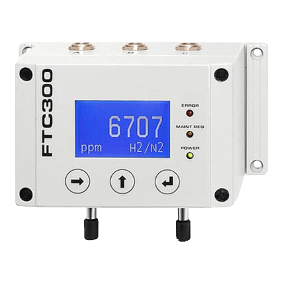
Page 18: The Front Panel
LED “System Alarm Indicator”. Setting of the conditions to trigger this relay is described in chapter 8.2.7. It is recommended to configure the “Error matrix” such that system errors of the device, see Appendix A, trigger the Status Alarm. Messkonzept GmbH · Niedwiesenstr. 33 · 60431 Frankfurt · Germany... -
Page 19: System Alarm Indicator (Red)
The <ENTER> calls the item, that is marked as selected by the black background. Menu items are selected by the <RIGHT> key. In submenus with an “ESC”/”OK” option the <ENTER> key confirms the selection of “ESC” or “OK”. Messkonzept GmbH · Niedwiesenstr. 33 · 60431 Frankfurt · Germany... -
Page 20: Switching On The Device
Pressing the <UP> key during warm up switches directly to operation screen and activates the current loop. The displayed concentration value is not precise until the block is warmed up. Messkonzept GmbH · Niedwiesenstr. 33 · 60431 Frankfurt · Germany... -
Page 21: Operation Screen
Selecting “Operation” as shown above and pressing <ENTER> or <UP> returns to the Operation screen. To access the submenus, select the desired submenu and press <ENTER>. The menu paths given in the following chapters start at the main menu. Messkonzept GmbH · Niedwiesenstr. 33 · 60431 Frankfurt · Germany... -
Page 22: Calibration
A substitute gas has at a certain concentration the same thermal conductivity as the test gas it is substituting, such it can also be used for the calibration instead. Please contact Messkonzept for details. 6.1 Set Offset Gas Concentration A1 A2 Er 0.30... -
Page 23: Set Gain Gas Concentration
Figure 6.1 Gain Gas Menu Prior to a two point calibration the gain gas concentration has to be set in the submenu “Gain Gas”. This menu is operated analogously “Offset Gas” menu described above. Messkonzept GmbH · Niedwiesenstr. 33 · 60431 Frankfurt · Germany... -
Page 24: Offset Calibration
0.00 100.00 Actu. 99.98 Calibration Actu. 0.00 ESC/OK ESC/OK ESC/OK Please Wait ESC/OK Figure 6.3 Calibrate Span Menu The menu structure is designed such that the gain calibration procedure is Messkonzept GmbH · Niedwiesenstr. 33 · 60431 Frankfurt · Germany... -
Page 25: Diagnosis
The parameter menu gives enables to scroll through the entire parameter list. Contact Messkonzept for detailed information on the parameter. The first line contains the name of the parameter, the last line its number. To move forward in the list, press <ENTER>, to move backwards, press <Up>. -
Page 26: Errors
To leave the parameter menu press <RIGHT> and <ENTER>. A reset of the errors is not necessary as errors that are no longer pending are immediately removed from the error list. Messkonzept GmbH · Niedwiesenstr. 33 · 60431 Frankfurt · Germany... -
Page 27: Setup
• In the “Output Setup” the properties of the external signal channels are set. • The “Expert Setup” gives write access to the parameters, reset functions, access modes and codes and test signals for subsequent connected equipment. Messkonzept GmbH · Niedwiesenstr. 33 · 60431 Frankfurt · Germany... -
Page 28: Unit Setup
1 and 4 when displaying Vol.%. The resolution in ppm is always 1ppm. All internal calculations are done in ppm. Access of measuring values via the RS-232 interface will always give the numbers in ppm with 1ppm resolution. Messkonzept GmbH · Niedwiesenstr. 33 · 60431 Frankfurt · Germany... -
Page 29: Measuring Gas Setup
The settings of relays, the scaling of the analog outputs and the measuring range do not change when using a different binary gas mixture. Messkonzept GmbH · Niedwiesenstr. 33 · 60431 Frankfurt · Germany... -
Page 30: Response Time Setup
A gas flow of 80l/h leads to a gas exchange time of under 0.5s measured from the gas inlet of the device. Messkonzept GmbH · Niedwiesenstr. 33 · 60431 Frankfurt · Germany... -
Page 31: Multi Gas Mode List (Useful With Option Mgm Only)
<RIGHT> key. This is indicated by the active gas mixture. By pressing <ENTER> the next binary gas mixture from the “List for MGM” is selected. Pressing <RIGHT> again deactivates the gas mixture selection. Messkonzept GmbH · Niedwiesenstr. 33 · 60431 Frankfurt · Germany... -
Page 32: Relays
Relay 1 can be operated in different modes described below. Selecting “Relay 1” and pressing <ENTER> gives access to the different modes. 1) “R 1Mode L/H” signalling from low to high When the measured concentration increases and reaches the threshold, Messkonzept GmbH · Niedwiesenstr. 33 · 60431 Frankfurt · Germany... -
Page 33: Relay 1 Threshold
ESC/OK Figure 8.8 Relay 1 Hysteresis Menu In the “R1 Hysteresis” menu the hysteresis value is set. The value is given in percent of the threshold value. Confirm with “OK”. Messkonzept GmbH · Niedwiesenstr. 33 · 60431 Frankfurt · Germany... -
Page 34: Relay 1 Failsafe / Not Failsafe
With “Calibration frozen” the relay does not respond to any changes of the measured concentration during the calibration procedure and stays in the state it was in when the calibration began. With “Calibration active” the Messkonzept GmbH · Niedwiesenstr. 33 · 60431 Frankfurt · Germany... -
Page 35: Relay 2 Mode
“Relay 2” provides all functionalities of“Relay 1”, see description above. In addition Relay 2 permits the external signaling of the “Maintenance” alarm or monitoring the external auxiliary signal with the menu “Aux.”. Messkonzept GmbH · Niedwiesenstr. 33 · 60431 Frankfurt · Germany... -
Page 36: Common Relay
If one or more of errors included in the Alarm matrix by “C. Alarm YES” are pending, the common relay triggers. In the factory settings all internal errors described in Appendix A are included in the common relay. Messkonzept GmbH · Niedwiesenstr. 33 · 60431 Frankfurt · Germany... -
Page 37: Current Loop
Adjust Loop Figure 8.13 Output Setup The FTC300 is equipped with three analog outputs. “Current Loop” is an isolated current output. “Analog Out 1” and “Analog Out 2” are not DC- isolated outputs with an output range from 0 to 10 V. - Page 38 When choosing the “Cal. active” option the currently measured value is shown at the current output during the calibration. When choosing the “Cal. frozen” the last measured value before the calibration began is shown at the current output. Messkonzept GmbH · Niedwiesenstr. 33 · 60431 Frankfurt · Germany...
-
Page 39: Analog Output 1
1 P134 Aux norm. Normalized signal applied to analog input 1 IOut Current Loop “AOut1-Offset” and “AOut-Gain” allow to scale the analog output according to a linear equation (Output= AOut1-Gain*signal+AOut1_Offset). Messkonzept GmbH · Niedwiesenstr. 33 · 60431 Frankfurt · Germany... -
Page 40: Adjust Loop
(e.g. with a multimeter) and enter the measured value in the third display line, then confirm with “OK” and <ENTER>. After successful adjustment the multimeter shows the value of 19.5mV. Messkonzept GmbH · Niedwiesenstr. 33 · 60431 Frankfurt · Germany... -
Page 41: Expert Setup
ESC/OK Figure 10.19 Expert Level Parameter Menu The configuration of the FTC300 is represented by a set of about 170 parameters. These parameters govern all settings and functions of the device. Press <ENTER> to scroll forward through the list and backwards by pressing <UP>. -
Page 42: Access Modes
Mode”. The operation mode is used with the setting “1.00000” in the menu “Mode Set” and “3.00000” for the safe mode. Each change in this mode requires the manual input of the actual Operator Code. Messkonzept GmbH · Niedwiesenstr. 33 · 60431 Frankfurt · Germany... -
Page 43: Reset Functions
When the device is reset to “Default Setting” the parameters relevant for the proper operation are overwritten by default values. With these values the device will not work. The correct parameters (contact Messkonzept) have to be written to the device again, see chapter 8.4.1 or the manual of SetApp under www.messkonzept.de... -
Page 44: Test Of Relays, Analog Outputs And Connections
11.4 V. The output “Current Loop” can be set to currents between 0 and 22mA. The analog outputs 1 and 2 can be set to supply a voltage between 0V and 10V. Messkonzept GmbH · Niedwiesenstr. 33 · 60431 Frankfurt · Germany... -
Page 45: Note
All test signals are permanently on until leaving the “I/O Test” menu. It is the responsibility of the expert to assure that the I/O test does not interfere with the subsequent connected systems and processes in an unintended way. Messkonzept GmbH · Niedwiesenstr. 33 · 60431 Frankfurt · Germany... -
Page 46: Appendix A System Errors
SetTemp– The device still warms up below specified 0.3°C or a sudden change of range ambient temperature, gas flow disturbed the temperature control loop. Wait for a couple of minutes. Messkonzept GmbH · Niedwiesenstr. 33 · 60431 Frankfurt · Germany... - Page 47 Send the device to specified range Messkonzept with description of error. EXT. ERROR Error routed from Signal Check the external unit input “DIN” (0V=no >14V surveyed by the external error, +24V=error) error. Messkonzept GmbH · Niedwiesenstr. 33 · 60431 Frankfurt · Germany...
-
Page 48: Appendix B Specifications
< 1% of smallest range per of flow at 80l/h 10l/h Gas pressure Max. 2000kPa (20 bar) Error due to change < 1% of smallest range per of pressure 10hPa (>800hPa) Messkonzept GmbH · Niedwiesenstr. 33 · 60431 Frankfurt · Germany... - Page 49 Typ. Number of Switches: Power Supply: Voltage range: 18V to 36V DC Max. Current: 700mA Typical Current: 300mA Interface: RS-232 Baud rate: 19.2 kbaud Data: 8 bit Parity: None Stop: Flow control: None Messkonzept GmbH · Niedwiesenstr. 33 · 60431 Frankfurt · Germany...
-
Page 50: Environmental Conditions
Vibration: 10 to 150Hz (2g peak) Protection class: IP 65 B.4 Dimensions Dimensions: Depth: 85mm Width: 145mm Height: 80mm without connectors Weight: Max. 1800g Mounting: Wall mounting Appendix C EG-Konformitätserklärung Messkonzept GmbH · Niedwiesenstr. 33 · 60431 Frankfurt · Germany... -
Page 51: Operating Manual
Operating Manual Messkonzept GmbH · Niedwiesenstr. 33 · 60431 Frankfurt · Germany... - Page 52 EN 55022 Erfüllt ** 20dB unter Grenzwerte Quasispitzenwert Untersuchtes Prüfmuster: FTC 200, Stand 12-2011 Prüfort/-zeit: EMV-Prüflabor, BIS Prozesstechnik GmbH, Frankfurt-Höchst, KW 49-2011, KW04-2012 Prüfer: Dipl.-Phys. H. Hahn, Quality-Engineering Hahn (Ingenieurbüro), Frankfurt Messkonzept GmbH · Niedwiesenstr. 33 · 60431 Frankfurt · Germany...
-
Page 53: Appendix D Menu Tree
|_R2 Mode/Aux; Low|High; High|Low; Maintnance; |_R2 Threshold |_R2 Hyst. |_Failsafe/Not Failsafe |_Cal. active/frozen |_Common Relay |_Alarm Matrix |_Failsafe/Not Failsafe |_Cal. active/frozen |_Output Set. |_Current Loop |_I/O Mode |_4-20mA |_C->IoutMin |_C->IoutMax |_4-20mA (Err) |_C->IoutMin |_C->IoutMax Messkonzept GmbH · Niedwiesenstr. 33 · 60431 Frankfurt · Germany... - Page 54 |_Operat. Code |_Expert Code |_Mode Set |_Reset Funct. |_Restart only |_Factory Set. |_Default Set. |_Save Calibr. |_I/O Test |_Relays |_Rel 1 open/closed |_Rel 2 open/closed |_Rel 3 open/closed |_DIN low/high Messkonzept GmbH · Niedwiesenstr. 33 · 60431 Frankfurt · Germany...
Need help?
Do you have a question about the FTC300 and is the answer not in the manual?
Questions and answers