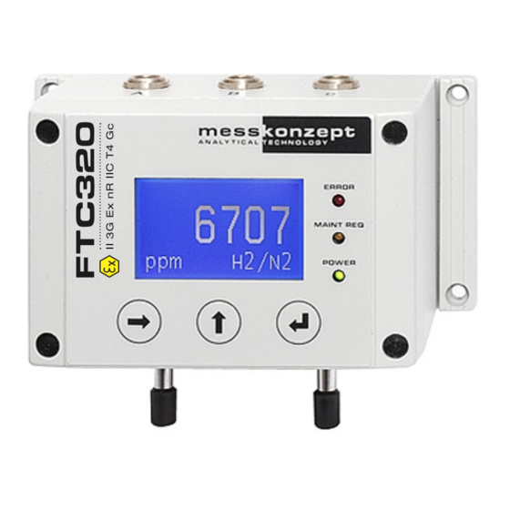
MessKonzept FTC320 Operating Manual
Gas analysis using thermal conductivity measurement
Hide thumbs
Also See for FTC320:
- Operating manual (46 pages) ,
- Operating manual (50 pages) ,
- Operating manual (64 pages)
Table of Contents
Advertisement
Quick Links
Advertisement
Table of Contents

Related Manuals for MessKonzept FTC320


Summary of Contents for MessKonzept FTC320
- Page 1 Operating Manual FTC320 Gas analysis using thermal conductivity measurement...
- Page 2 All information of technical nature and particulars of the product and its use (including the information in this manual) are given by Messkonzept in good faith. However, it is acknowledged that there may be errors or omissions in this manual. Images and drawings may not be in scale. For the latest revisions to this manual contact Messkonzept or visit www.messkonzept.de...
- Page 3 Page 2 of 41 Quick Installation Guide For quick installation of the FTC320 we recommend to read the following chapters of this manual: • Chapter 1 "Operator Safety": Important warnings, saftey instructions and intended use. • Chapter 3 "Assembly of the Instrument": Mounting, pneumatic and electric connection. Also see Chapter 10 "Appendix: Dimensional Drawing"...
-
Page 4: Table Of Contents
3.1 Installation of the FTC320 ........ - Page 5 9.5 Dimensions ......... . 39 10 Appendix: Dimensional Drawing File name: FTC320 Operating Manual_1.09KD201009MPO5V02.pdf...
-
Page 6: Operator Safety
This icon draws attention to application errors or actions that can lead to safety risks including the injury to persons or malfunctions, possibly even destruction of the device. This icon indicates an additional function or hint. File name: FTC320 Operating Manual_1.09KD201009MPO5V02.pdf... -
Page 7: Warning Notices
• Never open the housing of the FTC320, especially because of the loose glass balls. When the device had been opened it may not work safely with flammable gases. -
Page 8: Safety Instructions
The specifications of the device and its manual have to be observed strictly. Please fill out questionnaire (2.01.1FB180619MPL1) for registration of your measuring task, if your intended use does not comply with intended use described above. Based on the information given in the questionnaire Messkonzept will examine the measuring task and possibly authorize it. -
Page 9: Principle Of Measurement
Cross-sensitivity is the sensitivity of the measurement on other gases than the measured component. Perturbation-sensitivity means the sensitivity of the measurement on other influences than the gas-composition, e.g. the gas pressure. File name: FTC320 Operating Manual_1.09KD201009MPO5V02.pdf... - Page 10 The FTC320 contains a thermal conductivity sensor to analyze the quantitative composition of gas mix- tures. The measurement is based on the heat transfer between a heat source and a heat sink.
- Page 11 Table 2.1: Measuring ranges of typical gas compositions for analysis with the FTC320. The FTC320 must not be used with explosive gases. Flammable gases such as H may only be used in devices filled with glass balls. A gas mixture of a flammable gas with an inert gas in a mixing ratio such, that it is still inflammable for any amount of...
-
Page 12: Ftc320 Detector Unit
“On request“ can also be implemented upon request. 2.2 FTC320 Detector Unit The FTC320 detector unit consists of a hermetically sealed pressure proof stainless steel block with a gas duct, which is suited for pressures up to 20 bar. Sample gas entering through the gas inlet is guided to the micro-mechanical thermal conductivity sensor and further downstream to the outlet port. -
Page 13: Assembly Of The Instrument
Assembly of the Instrument 3.1 Installation of the FTC320 The FTC320 is designed for wall fastening. The four mounting holes are shown in Figure 3.1. M4 cylinder head bolts are suitable. Please remember to keep additional space for adequate assembly of gas hoses and cables (see Chapter 10 "Appendix: Dimensional Drawing"... -
Page 14: Gas Ports
Page 13 of 41 3.2 Gas Ports On the bottom of the FTC320 housing two tubes with 6mm outer diameter for gas connection are lo- cated. They are labeled with “GAS IN “ and “GAS OUT“. For low requirements regarding gas tightness and resistance to pressure the tubes can be used as hose connector. - Page 15 Relay 2 isolated contact; max. 30V, 0.5A blue Common Relay 3 isolated contact; max. 30V, 0.5A Common Relay 3 isolated contact; max. 30V, 0.5A Table 3.1: Connecting pin assignment of connectors A, B, C File name: FTC320 Operating Manual_1.09KD201009MPO5V02.pdf...
-
Page 16: Requirements For Electrical Connectors
The FTC320 is a device of protection class III. For power supply a source with PELV specification (Pro- tective Extra Low Voltage) according to EN 60204-1 must be used. See also Section 3.3.2 "Ground". - Page 17 If you plan to develop or use your own software solutions for communication via the RS-232 interface, you may need more detailed information on the available parameters, etc. Please contact Messkonzept in this regard. File name: FTC320 Operating Manual_1.09KD201009MPO5V02.pdf...
-
Page 18: The Front Panel
POWER Measurement Unit [Vol%] or [ppm] RIGHT / Selection Key ENTER / Terminate Key UP / Selection Key (Toggle MGM Mode) (Gas Selection in MGM-Mode) Figure 4.1: Front view schematic of the FTC320 front panel File name: FTC320 Operating Manual_1.09KD201009MPO5V02.pdf... -
Page 19: Display
The <ENTER> key calls the item that is marked as selected (selection is indicated through black background highlighted text). Menu items are selected by the <RIGHT> key. In sub- menus with an “ESC/OK“ option the <ENTER> key confirms the selection of “ESC“ or “OK“. File name: FTC320 Operating Manual_1.09KD201009MPO5V02.pdf... -
Page 20: Instrument Display
Act: 58.30 °C Figure 5.1: warm up screen of the FTC320 The warm up screen shows the current block temperature during warm up in the center of the screen (see Figure above). The target value of the block temperature, 63 C for the standard version or 70 C for the high temperature version, is shown in the bottom line of the screen. -
Page 21: Display Of One Measured Value
0.30 H2/N2 Figure 5.2: FTC320 operation screen (one measured parameter) In the center of the display the currently measured gas concentration is shown, the associated unit of the measurement (ppm or Vol.%) is indicated in the bottom left corner of the operation screen. The currently measured gas pair, e.g. -
Page 22: General Instrument Settings
By default, this is 222.0000. The code can be changed in the Expert Setup menu. 6.2 Diagnosis The FTC320 has several integrated diagnosis and test functions that can be accessed through the diagnosis-menu. The menu provides the following functions: •... -
Page 23: Parameter Menu
H2/N2 Figure 6.2: parameter menu for advanced diagnosis The configuration of the FTC320 is defined by a list of internal parameters. The “Parameter“ menu gives read-only access to these parameters. This may help an experienced user to diagnose malfunctions caused by wrong settings. The parameter menu allows you to scroll through the entire parameter list. -
Page 24: Instrument Setup
P56 (see Section 6.5.1) sets the number of digits after the decimals point between 1 and 4 when the display unit is set to Vol.%. The resolution in ppm is always 1 ppm. All internal calculations of the FTC320 are done in ppm.Values retrieved through the RS-232 interface will always be in ppm with 1ppm resolution. -
Page 25: Output Setup
Figure 6.6: Analog output setup menu The FTC320 is equipped with three analog outputs. “Current Loop“ is an isolated current output. “Ana- log Out 1“ and “Analog Out 2“ are not DC-isolated outputs with an output range from 0 to 10 V. In the ”Output Setup”... -
Page 26: Parameter
P009 Figure 6.8: Parameter change in expert mode The configuration of the FTC320 is represented by an internal list of parameters. These parameters govern all settings and functions of the device. In the expert-menu’s parameter list press <ENTER> to scroll forward through the list and backwards by pressing <UP>. Some parameters cannot be changed (e.g. -
Page 27: Access Modes
• “Default Set.“: Resets all parameters to the default set values. CAREFUL: These values are not suited for a properly working device, • “Save Calibration“: Saves the parameters relevant to calibration. They can be retrieved by “Fac- tory Set.“ File name: FTC320 Operating Manual_1.09KD201009MPO5V02.pdf... -
Page 28: Test Of Relays, Analog Outputs And Connections
With these values the device will not work properly. The correct parameters (contact Messkonzept) have to be written to the device again, see Section 6.5.1 or the manual of SetApp which you can find on www.messkonzept.de. - Page 29 Note! All test signals are permanently on until leaving the “I/O Test“ menu. It is the re- sponsibility of the expert to assure that the I/O test does not interfere with the subsequent connected systems and processes in an unintended way. File name: FTC320 Operating Manual_1.09KD201009MPO5V02.pdf...
-
Page 30: Measurand Related Settings
• On a regular cycle, depending on the precision aimed for. To find out the appropriate time between calibrations, we recommend to begin with a more frequent check of the calibration. The time between calibrations can range between: File name: FTC320 Operating Manual_1.09KD201009MPO5V02.pdf... - Page 31 Instead of using toxic or explosive gases for calibration, substitute gases may be used. A substitute gas has (at a certain concentration) the same thermal conductivity as the test gas it is substituting, such it can also be used for the calibration instead. Please contact Messkonzept for details on possible substitute gases for your application.
-
Page 32: Set Offset Gas Concentration
flow rate as in your process measurement situation. Confirming with “OK“ leads to the menu “Stability“. The second line contains the set test gas concentration (“Targ.“), the third line the measured concentration (“Actu. “) using the current (unchanged) calibration. Before File name: FTC320 Operating Manual_1.09KD201009MPO5V02.pdf... -
Page 33: Gain Calibration
Limit values and hysteresis can be set. Only one alarm can be set per gas. A triggered alarm is signaled by a flashing of the measured variable on the display. Alarms can be used to switch relays. File name: FTC320 Operating Manual_1.09KD201009MPO5V02.pdf... -
Page 34: Selection Of Alarm Groups
The setting is made in the measuring unit used (e.g. Vol % or ppm). In the FTC320 the hysteresis is implemented in such a way that an increasing measured value at [Upper Limit] + [Hysteresis] leads to triggering of the alarm at the upper limit and only switches off again when the measured variable has fallen to a value lower than [Upper Limit] - [Hysteresis]. -
Page 35: Appendix: System Errors
In case this does not lead to a solution, please contact Messkonzept and describe the circumstances that led to this error. Some issues can be resolved through remote maintenance. If the error persists you might be requested to send the FTC320 back to Messkonzept. Please pay attention to these points when sending the device: •... - Page 36 CAL VAR ER 1000ppm exceeding max. calibration gas flooded the allowed range device properly? Please verify your calibration setup and repeat the calibration. If the error persists, send the device to Messkonzept with description of error. File name: FTC320 Operating Manual_1.09KD201009MPO5V02.pdf...
- Page 37 TC-signal above TC MAX ER 7000mV Messkonzept with description specified range of error. Error routed from input “DIN“ Check the surveyed external EXT. ERROR Signal <14V (0V=no error, unit. +24V=error) Table 8.1: Description of System Errors File name: FTC320 Operating Manual_1.09KD201009MPO5V02.pdf...
-
Page 38: Appendix: Specifications
Error due to change of flow at 80 l/h 10 l/h Error due to change of pressure < 1 % of smallest range per (800 hPa < p < 1200 hPa) 10 hPa Table 9.1: Specification of TC measurement File name: FTC320 Operating Manual_1.09KD201009MPO5V02.pdf... -
Page 39: Electrical Specifications
Typical current draw: 500 mA Safeguard: PELV (Protective Extra Low Voltage) Digital Interface Type: RS-232 Baud rate: 19.2 kbaud Data: 8 bit Parity: None Stop: Flow control None Reference potential: ground Table 9.2: Electrical Specifications File name: FTC320 Operating Manual_1.09KD201009MPO5V02.pdf... -
Page 40: Permissible Conditions Of The Sample To Be Measured
IP 65 (if cables are plugged and/or all unused jacks are sealed using protective caps) Table 9.4: Environmental conditions 9.5 Dimensions Dimensions: Depth: 85 mm Width: 144 mm Height: 80 mm without connectors Weight: max. 1800 g Mounting: Wall mounting Table 9.5: Dimensions File name: FTC320 Operating Manual_1.09KD201009MPO5V02.pdf... -
Page 41: Appendix: Dimensional Drawing
Page 40 of 41 Chapter 10 Appendix: Dimensional Drawing File name: FTC320 Operating Manual_1.09KD201009MPO5V02.pdf... - Page 44 Messkonzept GmbH Analytical Technology Niedwiesenstr. 33 60431 Frankfurt Germany Telefon +49 69 53056444 +49 69 53056445 info@messkonzept.de www.messkonzept.de Managing Director Dr. Axel-Ulrich Grunewald Place of jurisdiction Frankfurt HRB 49940 VAT ID: DE211207233...
Need help?
Do you have a question about the FTC320 and is the answer not in the manual?
Questions and answers