MessKonzept FTC320 Operating Manual
Gas analysis using thermal conductivity measurement for zone 2 atex ii 3g ex nr iic t4 gc
Hide thumbs
Also See for FTC320:
- Operating manual (44 pages) ,
- Operating manual (50 pages) ,
- Operating manual (64 pages)

Related Manuals for MessKonzept FTC320


Summary of Contents for MessKonzept FTC320
- Page 1 Operating Manual FTC320 Ex Gas analysis using thermal conductivity measurement for zone 2 ATEX II 3G Ex nR IIC T4 Gc...
- Page 2 All information of technical nature and particulars of the product and its use (including the information in this manual) are given by Messkonzept in good faith. However, it is acknowledged that there may be errors or omissions in this manual. Images and drawings may not be in scale. For the latest revisions to this manual contact Messkonzept or visit www.messkonzept.de...
- Page 3 Page 2 of 43 Quick Installation Guide For quick installation of the FTC320 we recommend to read the following chapters of this manual: • Chapter 1 "Operator Safety": Important warnings, saftey instructions and intended use. • Chapter 3 "Assembly of the Instrument": Mounting, pneumatic and electric connection. Also see Chapter 10 "Appendix: Dimensional Drawing"...
-
Page 4: Table Of Contents
3.1 Installation of the FTC320 ........ - Page 5 Page 4 of 43 6.4 Output Setup ......... 26 6.5 Expert Setup .
-
Page 6: Operator Safety
Page 5 of 43 Chapter 1 Operator Safety This chapter provides information and warnings which must be followed to ensure safe operation and retain the instrument in safe condition. Read this section carefully before beginning to install and use the instrument. 1.1 Notes on Safety Conventions and Icons This icon draws attention to application errors or actions that can lead to safety risks including the injury to persons or malfunctions, possibly even destruction of the device. -
Page 7: Warning Notices
Page 6 of 43 1.2 Warning Notices • The operator must ensure that the above classification and marking on the device is suitable for the application. • The cables must be connected voltage-free. Do not disconnect while energized! • Permissible ambient temperature (when used as intended): -5 to +50 °C. •... -
Page 8: Safety Instructions
Any interruption in the protective earth can cause danger. • Pay regard to the local regulations and circumstances regarding electric installations. • Repairs may only be done by Messkonzept. 1.4 Safety instructions for use in explosion hazard areas Zone 2 Conformity with DIN EN 60079-15 "Explosive atmospheres - Part 15: Equipment protection by type of... - Page 9 The specifications of the device and its manual have to be observed strictly. Please fill out questionnaire (2.01.1FB180619MPL1) for registration of your measuring task, if your intended use does not comply with intended use described above. Based on the information given in the questionnaire Messkonzept will examine the measuring task and possibly authorize it.
-
Page 10: Principle Of Measurement
Page 9 of 43 Chapter 2 Principle of Measurement 2.1 Determining Concentrations via Thermal Conductivity Thermal Conductivity Detectors (TCD) are used in the chemical industry since the 1920s as the first process gas analyzers for the quantitative composition of gas mixtures. Every gas has a typical heat conductivity governed by its molar mass and viscosity. - Page 11 The FTC320 contains a thermal conductivity sensor to analyze the quantitative composition of gas mix- tures. The measurement is based on the heat transfer between a heat source and a heat sink.
- Page 12 Table 2.1: Measuring ranges of typical gas compositions for analysis with the FTC320. The FTC320 must not be used with explosive gases. Flammable gases such as H may only be used in devices filled with glass balls. A gas mixture of a flammable gas with an inert gas in a mixing ratio such, that it is still inflammable for any amount of...
-
Page 13: Ftc320 Detector Unit
“On request“ can also be implemented upon request. 2.2 FTC320 Detector Unit The FTC320 detector unit consists of a hermetically sealed pressure proof stainless steel block with a gas duct, which is suited for pressures up to 20 bar. Sample gas entering through the gas inlet is guided to the micro-mechanical thermal conductivity sensor and further downstream to the outlet port. -
Page 14: Assembly Of The Instrument
Assembly of the Instrument 3.1 Installation of the FTC320 The FTC320 is designed for wall fastening. The four mounting holes are shown in Figure 3.1. M4 cylinder head bolts are suitable. Please remember to keep additional space for adequate assembly of gas hoses and cables (see Chapter 10 "Appendix: Dimensional Drawing"... -
Page 15: Gas Ports
Page 14 of 43 3.2 Gas Ports On the bottom of the FTC320 housing two tubes with 6mm outer diameter for gas connection are lo- cated. They are labeled with “GAS IN “ and “GAS OUT“. For low requirements regarding gas tightness and resistance to pressure the tubes can be used as hose connector. - Page 16 Page 15 of 43 cables have open ends. The cross-section of the conductors in cable A and C is 0,14mm , for cable B 0,25mm . Cable A is shipped with devices set up for analog output. The protection class of the device is only effective with all cables attached. In case cable A is not used, connector plug A has to be closed with an end fitting.
- Page 17 Page 16 of 43 Wire Pin No. Function Description colour Connector (7 pins) white Analog Input 1 0 to 10V, 24 bit resolution brown Analog Output 2 0 to 10V, 16 bit resolution green GND for pins 1, 2, 6, 7 yellow Digital Input (DIN) low: <4.6V;...
-
Page 18: Requirements For Electrical Connectors
The FTC320 is a device of protection class III. For power supply a source with PELV specification (Pro- tective Extra Low Voltage) according to EN 60204-1 must be used. See also Section 3.4.2 "Ground". - Page 19 If you plan to develop or use your own software solutions for communication via the RS-232 interface, you may need more detailed information on the available parameters, etc. Please contact Messkonzept in this regard. File name: FTC320Ex Operating Manual_1.09KD201009MPO3V02.pdf...
-
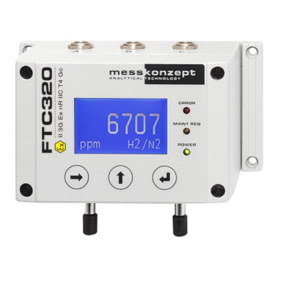
Page 20: The Front Panel
POWER Measurement Unit [Vol%] or [ppm] RIGHT / Selection Key ENTER / Terminate Key UP / Selection Key (Toggle MGM Mode) (Gas Selection in MGM-Mode) Figure 4.1: Front view schematic of the FTC320 front panel File name: FTC320Ex Operating Manual_1.09KD201009MPO3V02.pdf... -
Page 21: Display
Page 20 of 43 4.1 Display 4.2 Keys RIGHT / Selection Key On the operation screen, the <RIGHT> key can be used to select one of the measured variables displayed on the work screen. With the <ENTER> key the menu related to the measured parameter can be called up, in which, for example, the calibration routine of the parameter can be accessed. -
Page 22: Instrument Display
Act: 58.30 °C Figure 5.1: warm up screen of the FTC320 The warm up screen shows the current block temperature during warm up in the center of the screen (see Figure above). The target value of the block temperature, 63 C for the standard version or 70 C for the high temperature version, is shown in the bottom line of the screen. -
Page 23: Display Of One Measured Value
0.30 H2/N2 Figure 5.2: FTC320 operation screen (one measured parameter) In the center of the display the currently measured gas concentration is shown, the associated unit of the measurement (ppm or Vol.%) is indicated in the bottom left corner of the operation screen. The currently measured gas pair, e.g. -
Page 24: General Instrument Settings
By default, this is 222.0000. The code can be changed in the Expert Setup menu. 6.2 Diagnosis The FTC320 has several integrated diagnosis and test functions that can be accessed through the diagnosis-menu. The menu provides the following functions: •... -
Page 25: Parameter Menu
H2/N2 Figure 6.2: parameter menu for advanced diagnosis The configuration of the FTC320 is defined by a list of internal parameters. The “Parameter“ menu gives read-only access to these parameters. This may help an experienced user to diagnose malfunctions caused by wrong settings. The parameter menu allows you to scroll through the entire parameter list. -
Page 26: Instrument Setup
P56 (see Section 6.5.1) sets the number of digits after the decimals point between 1 and 4 when the display unit is set to Vol.%. The resolution in ppm is always 1 ppm. All internal calculations of the FTC320 are done in ppm.Values retrieved through the RS-232 interface will always be in ppm with 1ppm resolution. -
Page 27: Output Setup
Figure 6.6: Analog output setup menu The FTC320 is equipped with three analog outputs. “Current Loop“ is an isolated current output. “Ana- log Out 1“ and “Analog Out 2“ are not DC-isolated outputs with an output range from 0 to 10 V. In the ”Output Setup”... -
Page 28: Parameter
P009 Figure 6.8: Parameter change in expert mode The configuration of the FTC320 is represented by an internal list of parameters. These parameters govern all settings and functions of the device. In the expert-menu’s parameter list press <ENTER> to scroll forward through the list and backwards by pressing <UP>. Some parameters cannot be changed (e.g. -
Page 29: Access Modes
Page 28 of 43 6.5.2 Access Modes Parameter Operat. Code Operat. Code Access Modes set: 111.000 Expert Code Reset Funct. new: 111.000 Operat. Mode ESC/OK I/O Test Operat. Code Expert Code set: 222.000 Expert Code new: 222.000 Operat. Mode ESC/OK Operat. -
Page 30: Test Of Relays, Analog Outputs And Connections
With these values the device will not work properly. The correct parameters (contact Messkonzept) have to be written to the device again, see Section 6.5.1 or the manual of SetApp which you can find on www.messkonzept.de. - Page 31 Page 30 of 43 • Voltage for Analog Out 1 • Voltage for Analog Out 2 The digital input “DIN“ is “low“ for voltages below 4.6V and “high“ above 11.4 V. The output “Current Loop“ can be set to currents between 0 and 22mA. The analog outputs 1 and 2 can be set to supply a voltage between 0V and 10V.
-
Page 32: Measurand Related Settings
Page 31 of 43 Chapter 7 Measurand related settings For each measured variable, usually given by a gas concentration, measurand related settings can be changed. The settings related to the measured parameter can be accessed from the working screen by selecting the measured parameter with the <RIGHT>... - Page 33 Instead of using toxic or explosive gases for calibration, substitute gases may be used. A substitute gas has (at a certain concentration) the same thermal conductivity as the test gas it is substituting, such it can also be used for the calibration instead. Please contact Messkonzept for details on possible substitute gases for your application.
-
Page 34: Set Offset Gas Concentration
Page 33 of 43 7.1.1 Set Offset Gas Concentration 2.58 % 2.58 % Offset Gas Calibrate set: 0.00000 Calibration Offset Gas new: 0.00000 Alarm Setup Gain Gas ESC/OK Figure 7.2: offset gas setup menu Before performing a calibration, the concentrations of the used test gases have to be set. In the sub- menu “Offset Gas“... -
Page 35: Gain Calibration
Page 34 of 43 continuing, wait for a sufficient running-in time to evacuate possible disturbing gases from the device. Only continue if the value of the actually measured concentration reaches a final value (you might ob- serve some signal noise around a constant value). To start the calibration sampling, select “OK“ and press <ENTER>. -
Page 36: Selection Of Alarm Groups
The setting is made in the measuring unit used (e.g. Vol % or ppm). In the FTC320 the hysteresis is implemented in such a way that an increasing measured value at [Upper Limit] + [Hysteresis] leads to triggering of the alarm at the upper limit and only switches off again when the measured variable has fallen to a value lower than [Upper Limit] - [Hysteresis]. -
Page 37: Appendix: System Errors
In case this does not lead to a solution, please contact Messkonzept and describe the circumstances that led to this error. Some issues can be resolved through remote maintenance. If the error persists you might be requested to send the FTC320 back to Messkonzept. Please pay attention to these points when sending the device: •... - Page 38 Error reading or Repeat procedure. If the error writing data to or persists, send the device to EEPROM ERROR from internal Messkonzept with description FLASH-EEPROM of error. Check if the used test gas concentration accords with the Calibration gain set concentration. Repeat CAL GAIN ER exceeding max.
- Page 39 Consider the device specifications. If the error persists, send the device to Messkonzept with description of error. Block temperature BT MAX ER above specified SetTemp+0.6K See BT MIN ER.
-
Page 40: Appendix: Specifications
Page 39 of 43 Chapter 9 Appendix: Specifications 9.1 Specification of Thermal Conductivity Measurement Attribute Range / Precision Linearity < 1 % of range Approx. 20 min; up to 1 h for Warm up time small measuring ranges 10 l/h - 150 l/h, Flow rate 60 l/h - 80 l/h (recommended) <... -
Page 41: Electrical Specifications
Page 40 of 43 9.2 Electrical Specifications Unit / Interface Feature Value Display 128 x 64 dot graphic LCD Keypad 3 short-travel keys Analog Input 1/2 Voltage range: 0 to 10 V Reference potential: ground Input resistance approx. 50 k Resolution 24 bit Current Loop... -
Page 42: Permissible Conditions Of The Sample To Be Measured
Page 41 of 43 9.3 Permissible Conditions of the sample to be measured Standard version: max. 20 bar abs. Pressure (absolute) with flow measurement: max. 2 bar abs. for flammable gases: max. 3 bar abs. At 60 l/h: Gas temperature - max. -
Page 43: Appendix: Dimensional Drawing
Page 42 of 43 Chapter 10 Appendix: Dimensional Drawing File name: FTC320Ex Operating Manual_1.09KD201009MPO3V02.pdf... - Page 46 Messkonzept GmbH Analytical Technology Niedwiesenstr. 33 60431 Frankfurt Germany Telefon +49 69 53056444 +49 69 53056445 info@messkonzept.de www.messkonzept.de Managing Director Dr. Axel-Ulrich Grunewald Place of jurisdiction Frankfurt HRB 49940 VAT ID: DE211207233...
Need help?
Do you have a question about the FTC320 and is the answer not in the manual?
Questions and answers