Table of Contents
Advertisement
Quick Links
Advertisement
Table of Contents

Subscribe to Our Youtube Channel
Related Manuals for Verity Audio SM05E


Summary of Contents for Verity Audio SM05E
- Page 1 5 INCH DIGITAL MONITOR SYSTEM Part # SM05E Just View It! ® Please read this manual completely before operating the SYSTEM A division of Component Solution Services, LLC. 56600 Twin Branch Dr., Mishawaka, IN 46545 www.verityrvs.com © 2016 Verity Rear Vision Systems...
-
Page 2: System Features
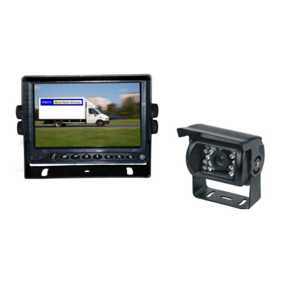
SYSTEM FEATURES MONITOR SPECIFICATIONS Screen size: 5-inch digital screen (16:9) Long Life High Resolution: 640 x 480 Pixel (RGB) System: NTSC Contrast: 450:1 Brightness: 450cd/m2 Power supply: DC 12V~32V with reverse polarity protection Operation temperatures: -30~70C Storage temperature: -40~80C 3 AV inputs with color coded trigger wires, auto blue screen if no signal on activated channel Features: sunshade, auto light sensor dimming for LCD screen, high quality processor, in-line... -
Page 3: System Components
SYSTEM COMPONENTS I/F Remote 5-Inch HD Digital Panel 65 foot Camera Cable C001E Camera 13-pin to Monitor Cable Manual... - Page 4 SYSTEM COMPONENTS This monitor can be mounted on the dash and can be mounted on both horizontal and vertical surfaces. Make sure the view is suitable to the driver to observe the images. Take care not to block any necessary viewing area when mounting.
- Page 5 MONITOR / UNVERSAL REMOTE OPERATIONS POWER: Manual turns on monitor. Monitor will also power up on command if a trigger wire is connected AV: Switches between cameras : decreases a selected menu item MENU: Activates operational menu (press repeatedly to move down the options) + : increases selected menu item POWER...
-
Page 6: Connection Operations
CONNECTION OPERATIONS Verity Rear Vision Systems Wire Connection Key 4-pin camera connectors & trigger wires Camera 1 rear (Brown trigger wire) Camera 2 (Green trigger wire) Camera 3 (Blue trigger wire) Red wire to key-on hot (+) 10-32v. DC (fused) Black wire to GND. -
Page 7: Menu Operations
MENU OPERATIONS Press Menu: Press the (+) key to advance to the next menu screens. Menu Screens are PICTURE, VOLUME, OPTION, SYSTEM. Screen 1: Depress menu repeatly to scroll down options. Use the (-) and (+) buttons on monitor to increase or decrease values. - Page 8 3 PICTURE: Picture refers to picture delay. This determines how long a camera stays on past the trigger wire being deactivated (powered). This allows for using the turn signal flasher wire as a trigger. PICTURE PICTURE CAMERA1 CAMERA2 CAMERA3 4 SYSTEM: LANGAUGE The default language is English.
- Page 9 Verity Rear Vision Systems A division of COMPONENT SOLUTION SERVICES (CSS) LIMITED ONE (1) YEAR WARRANTY 1. CSS products’ warranties are not transferable. The warranties apply to the retail consumer for one (1) year and covers against defects in material and workmanship. 2.
Need help?
Do you have a question about the SM05E and is the answer not in the manual?
Questions and answers