
Related Manuals for BK Precision 4017


Summary of Contents for BK Precision 4017
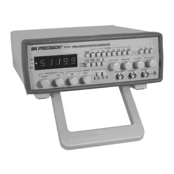
- Page 1 (217) 352-9330 | Click HERE Find the B&K Precision 4017 at our website:...
- Page 2 INSTRUCTION MANUAL MODEL 4017A MANUAL DE MODELO 4017A INSTRUCCIONES 10 MHz SWEEP FUNCTION GENERATOR with DIGITAL DISPLAY 10MHz GENERADOR DE BARRIDO/FUNCIONES CON EXHIBICION DIGITAL Artisan Technology Group - Quality Instrumentation ... Guaranteed | (888) 88-SOURCE | www.artisantg.com...
-
Page 3: Test Instrument Safety
TEST INSTRUMENT SAFETY WARNING Normal use of test equipment exposes you to a certain amount of danger from electrical shock because testing must sometimes b e performed where exposed voltage is present. An electrical shock causing 10 milliamps of current to pass through the heart wil l stop most human heartbeats. - Page 4 Instruction Manual Model 4017A 10 MHz SWEEP/FUNCTION GENERATOR with Digital Display 22820 Savi Ranch Parkway • Yorba Linda • CA 92887-4610 Phone: (714) 921-9095 • Fax: (714) 921-6422 • www.bkprecision.com Artisan Technology Group - Quality Instrumentation ... Guaranteed | (888) 88-SOURCE | www.artisantg.com...
-
Page 5: Table Of Contents
TABLE OF CONTENTS Page Page TEST INSTRUMENT SAFETY ....inside front cover MAINTENANCE............15 INTRODUCTION ............. 4 Fuse Replacement ............15 SPECIFICATIONS ............5 Instrument Repair Service ..........15 CONTROLS AND INDICATORS........7 CUSTOMER SUPPORT..........16 OPERATING INSTRUCTIONS ......... 9 WARRANTY SERVICE INSTRUCTIONS ...... -
Page 6: Introduction
INTRODUCTION triangle waves over the 0.1Hz to 10MHz range. This encompasses subaudible, audio, ultrasonic, and RF applications. The B+K Precision Model 4017A Sweep/Function A continuously variable dc offset allows the output to be injected Generator is a versatile signal source which combines several directly into circuits at the correct bias level. -
Page 7: Specifications
SPECIFICATIONS FREQUENCY CHARACTERISTICS SQUARE WAVE 0.1Hz to 100kHz ≤2% Symmetry Waveforms Sine, Square, Triangle, ± Pulse, ± Ramp ≤30nS Rise Time Range 0.1Hz to 10MHz in 8 ranges TRIANGLE WAVE ≥98% to 100kHz Resolution 5 digits Linearity Tuning Range Coarse: 10:1, Fine: ±5% of Coarse Setting Variable Duty Cycle 15:85:15 Continuously Variable TTL OUTPUT... - Page 8 SPECIFICATIONS SWEEP OPERATION Mode LIN / LOG Width 100:1, Continuously variable Rate 0.5 sec to 30 sec, continuously variable Sweep Output 0 to 10V FREQUENCY COUNTER Accuracy Time Base Accuracy ±1 count Time Base Accuracy ±10PPM (23 °C ±5 °C) Display 5 digit LED POWER SOURCE...
-
Page 9: Controls And Indicators
CONTROLS AND INDICATORS FRONT PANEL (Refer to Fig. 1) POWER Switch. Turns power on and off. RANGE Switch. Selects output frequency range. Seven ranges from 1 Hz to 10MHz. Switch indicates maximum frequency of range and is adjusted with COARSE FREQUENCY control to 0.1 times the maximum. For example, if the 100 kHz range is selected, the output frequency can be adjusted from 10kHz to 100kHz. - Page 10 CONTROLS AND INDICATORS 22. GATE LED. Indicates when the frequency counter 17. DUTY CYCLE Switch. When engaged, enables operation display is updated. When the 100K through 10M of DUTY CYCLE control (10). ranges are selected, the LED will flash 10 times per 18.
-
Page 11: Operating Instructions
Figure 1. Model 4017A Front Panel. OPERATING INSTRUCTIONS The B+K Precision Model 4017A Sweep/Function Generator is a versatile instrument, capable of producing a variety of output waveforms over a broad range of frequencies. To gain a working familiarity with the unit, it is recommended that it be connected initially to an oscilloscope, so that the effects of the various controls on the output waveforms can be observed. -
Page 12: Considerations
OPERATING INSTRUCTIONS . A superimposed DC component can be added to the output signal by engaging the DC OFFSET switch (14) to enable operation of the DC OFFSET control (5). Rotation of this control adds a positive or negative DC component to the output signal. -
Page 13: Duty Cycle Control
OPERATING INSTRUCTIONS 6. Remember that the output signal swing of the generator is limited to ±10 volts open circuited or ±5 volts into 50 Ω, and applies to the combined peak-to-peak signal and DC offset. Clipping occurs slightly above these levels. Fig. 3 illustrates the various operating conditions encountered when using the DC offset. -
Page 14: Ttl/Cmos Output
OPERATING INSTRUCTIONS TTL/CMOS OUTPUT 1. The end frequency of the sweep (lowest frequency) can be adjusted by rotating the SWEEP WIDTH control (16). This The TTL/CMOS output jack provides a fast rise time square adjustment should generally be made after setting the starting wave output. -
Page 15: Voltage Controlled Frequency Operation
OPERATING INSTRUCTIONS 2. Set the starting frequency with the COARSE control. Damage of this type usually occurs by accidentally Apply a positive DC voltage to the VCG/SWEEP input connecting the output of the function generator to a voltage jack (9) to decrease the frequency. A voltage from 0 to in the equipment under test. -
Page 16: Function Generator Applications Guidebook
OPERATING INSTRUCTIONS Figure 5. Circuit for Protection of TTL Output. FUNCTION GENERATOR APPLICATIONS GUIDEBOOK B+K Precision offers a “Guidebook to Function Generators” which describes numerous applications for this instrument, including hook- up details. It also includes a glossary of function generator terminology and an explanation of function generator circuit op eration. It maybe downloaded for free off our website at www.bkprecision.com. -
Page 17: Maintenance
MAINTENANCE WARNING The following instructions are for use by qualified service INSTRUMENT REPAIR SERVICE personnel only. To avoid electrical shock, do not perform servicing other than contained in the operating instructions unless you are qualified to do so. Because of the specialized skills and test equipment required for instrument repair and calibration, many Remember that ac line voltage is present on line voltage input customers prefer to rely upon B+K PRECISION for... -
Page 18: Customer Support
CUSTOMER SUPPORT 1-800-462-9832 B+K Precision offers courteous, professional technical support before and after the sale of their test instruments. The following services are typical of those available from our toll-free telephone number: Technical advice on the use of your instrument. ... -
Page 19: Warranty Service Instructions
(Pacific Daylight Time summer) Service Information Warranty Service: Please return the product in the original packaging with proof of purchase to the address below. Clearly state in writing the performance problem and return any leads, probes, connectors and accessories that you are using with the device. Non-Warranty Service: Return the product in the original packaging to the address below. -
Page 20: Limited Two-Year Warranty
Limited Two-Year Warranty B&K Precision Corp. warrants to the original purchaser that its products and the component parts thereof, will be free from defects in workmanship and materials for a period of two years from date of purchase. B&K Precision Corp. will, without charge, repair or replace, at its option, defective product or component parts. Returned product must be accompanied by proof of the purchase date in the form of a sales receipt. - Page 21 714-921-9095 TEST INSTRUMENT SAFETY (continued from inside front cover) 6. Some equipment with a two-wire ac power cord, including some with polarized power plugs, is the “hot chassis” type. This includes most recent television receivers and audio equipment. A plastic or wooden cabinet insulates the chassis to protect the custom er. When the cabinet is removed for servicing, a serious shock hazard exists if the chassis is touched.
-
Page 22: Spanish Manual
22820 Savi Ranch Parkway • Yorba Linda • CA 92887-4610 Phone: (714) 921-9095 • Fax: (714) 921-6422 • www.bkprecision.com © 2005 B+K Precision Printed in U.S.A. 480-311-9-001 V050114 Artisan Technology Group - Quality Instrumentation ... Guaranteed | (888) 88-SOURCE | www.artisantg.com...
Need help?
Do you have a question about the 4017 and is the answer not in the manual?
Questions and answers