Sign In
Upload
Download
Table of Contents
Contents
Add to my manuals
Delete from my manuals
Share
URL of this page:
HTML Link:
Bookmark this page
Add
Manual will be automatically added to "My Manuals"
Print this page
×
Bookmark added
×
Added to my manuals
Manuals
Brands
BK Precision Manuals
Portable Generator
4007B
User manual
BK Precision 4007B User Manual
Dds function generator
Hide thumbs
1
2
3
4
5
6
7
Table Of Contents
8
9
10
11
12
13
14
15
16
17
18
19
20
21
22
23
24
25
26
27
28
29
30
31
32
33
34
35
36
page
of
36
Go
/
36
Contents
Table of Contents
Bookmarks
Table of Contents
Table of Contents
1 Introduction
Description
Specifications
2 Installation
Introduction
Package Contents
Instrument Mounting
Power Requirements
Fuse Replacement
Grounding Requirements
Signal Connections
3 Operating Instructions
General Description
Display Window
Front Panel Controls
Connectors
Output Connections
MENU Keys
WAVEFORM Keys
UTILITY Key
SWEEP Key
ON Key
Cursor Keys
Rotary Input Knob
Power-On Settings
Memory
Displaying Errors
Quick Start
Selecting a Standard Waveform
Setting the Output
Using Voltage Offset
Storing and Recalling a Waveform Generator Setup
Advertisement
Quick Links
Download this manual
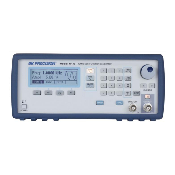
Model: 4007B, 4013B
DDS Function
Generator
USER MANUAL
Table of
Contents
Previous
Page
Next
Page
1
2
3
4
5
Advertisement
Table of Contents
Need help?
Do you have a question about the 4007B and is the answer not in the manual?
Ask a question
Questions and answers
Related Manuals for BK Precision 4007B
Portable Generator BK Precision 4001A Instruction Manual
Sweep function generator (18 pages)
Portable Generator BK Precision 4003A Instruction Manual
Sweep function generator (18 pages)
Portable Generator BK Precision 4007DDS Instruction Manual
7 mhz sweep function generator (13 pages)
Portable Generator BK Precision 4017 Instruction Manual
10 mhz sweep function generator (23 pages)
Portable Generator BK Precision 4014B User Manual
Dds function generator (52 pages)
Portable Generator BK Precision 4014B User Manual
Dds function generator (82 pages)
Portable Generator BK Precision 4014B Manual
Function generator (13 pages)
Portable Generator BK Precision BK4053B User Manual
Function/arbitrary waveform generator (141 pages)
Portable Generator BK Precision 4060B Series User Manual
Dual channel function/arbitrary waveform generators (92 pages)
Portable Generator BK Precision 4040 Manual Book
Guidebook to function generators (20 pages)
Portable Generator BK Precision 4047B User Manual
Dual channel function/arbitrary waveform generator (76 pages)
Portable Generator BK Precision 4013B User Manual
Dds function generator (36 pages)
Portable Generator BK Precision 4055B User Manual
Function/arbitrary waveform generator (141 pages)
Portable Generator BK Precision 4054B User Manual
Function/arbitrary waveform generator (141 pages)
Portable Generator BK Precision 4075 User Manual
25 mhz arbitrary function generator (103 pages)
Portable Generator BK Precision 4078 User Manual
25 mhz arbitrary function generator (103 pages)
This manual is also suitable for:
4013b
Table of Contents
Print
Rename the bookmark
Delete bookmark?
Delete from my manuals?
Login
Sign In
OR
Sign in with Facebook
Sign in with Google
Upload manual
Upload from disk
Upload from URL


Need help?
Do you have a question about the 4007B and is the answer not in the manual?
Questions and answers