
Related Manuals for BK Precision 4047B


Summary of Contents for BK Precision 4047B
- Page 1 Model: 4047B Dual Channel Function/Arbitrary Waveform Generator USER MANUAL GlobalTestSupply www. .com Find Quality Products Online at: sales@GlobalTestSupply.com...
-
Page 2: Safety Summary
Safety Summary The following safety precautions apply to both operating and maintenance personnel and must be followed during all phases of operation, service, and repair of this instrument. Before applying power to this instrument: Read and understand the safety and operational information in this manual. ... - Page 3 specified in this manual for this instrument. You must ensure that each accessory you use with this instrument has a category rating equal to or higher than the instrument's category rating to maintain the instrument's category rating. Failure to do so will lower the category rating of the measuring system. Electrical Power This instrument is intended to be powered from a CATEGORY II mains power environment.
- Page 4 The instrument is designed to be used in office-type indoor environments. Do not operate the instrument In the presence of noxious, corrosive, or flammable fumes, gases, vapors, chemicals, or finely- divided particulates. In relative humidity conditions outside the instrument's specifications. ...
- Page 5 Do not clean the instrument, its switches, or its terminals with contact cleaners, abrasives, lubricants, solvents, acids/bases, or other such chemicals. Clean the instrument only with a clean dry lint-free cloth or as instructed in this manual. Not for critical applications This instrument is not authorized for use in contact with the human body or for use as a component in a life-support device or system.
- Page 6 Servicing Do not substitute parts that are not approved by B&K Precision or modify this instrument. Return the instrument to B&K Precision for service and repair to ensure that safety and performance features are maintained. Cooling fans This instrument contains one or more cooling fans. For continued safe operation of the instrument, the air inlet and exhaust openings for these fans must not be blocked nor must accumulated dust or other debris be allowed to reduce air flow.
-
Page 7: Compliance Statements
Compliance Statements Disposal of Old Electrical & Electronic Equipment (Applicable in the European Union and other European countries with separate collection systems) This product is subject to Directive 2002/96/EC of the European Parliament and the Council of the European Union on waste electrical and electronic equipment (WEEE), and in jurisdictions adopting that Directive, is marked as being put on the market after August 13, 2005, and should not be disposed of as unsorted municipal waste. - Page 8 CE Declaration of Conformity This instrument meets the requirements of 2006/95/EC Low Voltage Directive and 2004/108/EC Electromagnetic Compatibility Directive with the following standards. Low Voltage Directive EN61010-1: 2001 EMC Directive EN 61000-3-2: 2006 EN 61000-3-3: 1995+A1: 2001+A2: 2005 EN 61000-4-2 / -3 / -4 / -5 / -6 / -11 EN 61326-1: 2006 GlobalTestSupply www.
-
Page 9: Safety Symbols
Safety Symbols Refer to the user manual for warning information to avoid hazard or personal injury and prevent damage to instrument. Electric Shock hazard Alternating current (AC) Chassis (earth ground) symbol. Ground terminal On (Power). This is the In position of the power switch when instrument is ON. -
Page 10: Table Of Contents
Contents Safety Summary ..................... 2 Compliance Statements ......................7 Safety Symbols ........................9 General Information ................. 13 1.1 Product Overview ......................13 1.2 Package Contents ......................13 1.3 Front Panel Overview ....................14 1.4 Rear Panel Overview ..................... 15 1.5 Display Overview......................16 Getting Started ................. - Page 11 3.8.2 Setting the Output ..................38 3.8.3 Using Voltage Offset ..................38 3.8.4 Storing and Recalling a Waveform Generator Setup ........39 3.8.5 Creating an Arbitrary Waveform ..............40 3.8.6 Entering Individual Data Points ............... 40 3.8.7 Setting the Arbitrary Frequency ..............41 3.8.8 Setting the Amplitude ..................
- Page 12 Troubleshooting Guide ..............72 Specifications ..................74 SERVICE INFORMATION ................78 LIMITED THREE-YEAR WARRANTY ..............79 GlobalTestSupply www. .com Find Quality Products Online at: sales@GlobalTestSupply.com...
-
Page 13: General Information
General Information 1.1 Product Overview The 4047B is a versatile dual-channel function generator with arbitrary capabilities. Implemented using a DDS (direct digital synthesis) architecture, this instrument generates stable and precise sine, square, triangle, and arbitrary waveforms. The unit also provides linear and logarithmic sweep for users needing sweep capability. -
Page 14: Front Panel Overview
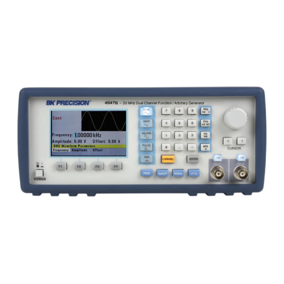
1.3 Front Panel Overview Figure 1 - Front Panel Overview Front Panel Description Power On/Off Switch Function Keys (F1-F4) Mode Key Sweep Key Channel Key Modulation Key Utility Key Enter Key Output BNCs Output On/Off Key Rotary Knob and Cursor Keys Units Keys Numeric Keypad Waveform Keys... -
Page 15: Rear Panel Overview
The front-panel controls select, display, and change parameter, function, and mode settings. Use the numerical keypad, rotary input knob and the cursor movement keys to enter data into the waveform generator. To change a setting: 1. Press the key that leads to the parameter to change. 2. -
Page 16: Display Overview
1.5 Display Overview The function generator has a color LCD display that can display up to 400 x 240 dots. When powering on the unit, sine waveform is selected and current settings will appear in the display. The bottom of the display shows a menu (selectable with function keys) that corresponds to the function, parameter, or mode display selected. -
Page 17: Getting Started
Getting Started Before connecting and powering up the instrument, please review and go through the instructions in this chapter. 2.1 Input Power and Fuse Requirements Input Power The instrument has a universal AC input that accepts line voltage and frequency input within: 90 V to 264 V, 48 Hz to 66 Hz The maximum power consumption is 30 VA. -
Page 18: Connectors
Fuse box Fuse box slit Check/Remove Fuse Figure 4 - Fuse Replacement 2.2 Connectors The function generator has two BNC connectors on the front panel where you can connect coaxial cables. These coaxial cables serve as carrier lines for output signals delivered from the function generator. -
Page 19: Preliminary Check
2.4 Preliminary Check The 4047B is intended for bench use. The instrument includes a front feet tilt mechanism for optimum panel viewing angle. The instrument does not require special cooling when operated within conventional temperature limits. - Page 20 finishes the diagnostic self-test routine, it enters the local state (LOCS) and assumes power-on default settings. Output Check Follow the steps below to do a quick check of the settings and waveform output. 1. Turn on the instrument and set the instrument to default settings. To set to default, press Setups, press Recall, and select 0 Default Setup.
-
Page 21: Operating Instructions
Operating Instructions 3.1 Menu Keys These keys select the main menus for displaying or changing a parameter, function, or mode. 3.1.1 WAVEFORM Keys These keys select the waveform output and display the waveform parameter menu (frequency, amplitude and offset). Figure 5 - Sine Menu F1: Frequency –... -
Page 22: Mode Key
(Vp-p)/2 + |offset| <= 5 volts F4: Symmetry – When the Square or Triangle waveforms are selected, the SYMMETRY (duty cycle) parameter is available. Change the symmetry (Triangle) or duty cycle (Square) by using the cursor keys, rotary knob, or numerical keys. If a certain setting cannot be produced, the waveform generator will display a warning message. - Page 23 F1: Continuous – Selects continuous output. F2: Triggered – Triggers one output cycle of the selected waveform for each trigger event. F3: Gated – Triggers output cycles as long as the trigger source asserts the gate signal. F4: Burst – Triggers ‘N’ number of output cycles for each trigger event, where N ranges from 2 to 65,535.
-
Page 24: Utility Key
Figure 9 - Burst Menu 3.1.3 UTILITY Key Utility Menu F1: Recall/Store – Recalls a previously stored front-panel setup from the selected buffer. Change the buffer number by using the rotary input knob. Valid storage buffer numbers are from 1 to 19 Buffer 0 is the factory default setup. –... -
Page 25: Sweep Key
F4: COUNTER – Enables the built-in frequency counter. The frequency of the signal connected to the TRIG IN connector will be displayed. The counter is auto ranging with up to 8 digits of resolution. Figure 10 - Counter Screen Press F1 - Off to turn off the counter. 3.1.4 SWEEP Key Selects the Sweep Mode and allows entering of sweep parameters: Sweep Start, Sweep Stop, and Sweep Rate. -
Page 26: Modulation Key
F3: Logarithmic – Selects the Logarithmic sweep shape. F4: Set – Defines the Sweep Start and Stop frequencies. Figure 12 - Set Sweep Menu 3.1.5 MODULATION Key Selects the AM, FM, FSK, PM, or PWM modulation mode. To select the output mode, press MODUL key, then press the function key that corresponds to the desired menu option, as shown: Figure 13 - Modulation Menu 1 of 2 Press F2 to select AM menu:... - Page 27 Figure 14 - AM Menu F1: % - Defines the modulation depth (from 0 to 100%) F2: Frequency - Selects the modulation frequency, from 0.1 Hz to 20.00 kHz. F3: Shape - Selects the modulating waveform between Sine, Square, or Triangle. F4: External - Selects and enables the external modulation by an external signal applied to the Modulation In connector on the rear panel.
- Page 28 F4: External - Selects and enables the external modulation by an external signal applied to the Modulation In connector on the rear panel. Figure 16 - Modulation Menu 2 of 2 Press F1 to select FSK menu: Figure 17 - FSK Menu F1: F-LO - Defines the low frequency of the FSK.
- Page 29 Figure 18 - PM Menu F1: Deviation - Defines the phase deviation of the PM in degrees. F2: Frequency - Defines the PM frequency. F3: Shape - Selects the shape of the modulating waveform between Sine, Triangle, or Square. F4: External - Selects and enables the external modulation by an external signal applied to the Modulation In connector on the rear panel.
- Page 30 3.1.6 PULSE Key Selects the Pulse waveform menu shown below: Figure 20 – Pulse Menu F1: Frequency/Period - Selects the parameter definition of the Pulse repetition period. F2: Amplitude - Selects the Amplitude parameter. In Arbitrary mode, this setting defines the maximum peak-to-peak amplitude of a full-scale waveform.
-
Page 31: Arbitrary Key
3.1.7 Pulse Width and Edge Edit Menu Figure 21 - Pulse Width and Edge Edit Menu F1: Width - Selects the Width of the generated pulse. F2: Equal Edge - Selects equal Rise (Leading edge) and Fall (Trailing edge) times of the pulse. F3: Lead/Trail - Selects different Rise and Fall times of the Pulse. - Page 32 can't produce the waveform at the desired frequency, the waveform generator will display an “Out of Range” error message. Displays the Point Rate (for Arbitrary Waveform only). The Rate parameter governs the rate at which waveform points are executed and thus the frequency of the output.
-
Page 33: Arbitrary Edit Menu
3.1.9 Arbitrary EDIT Menu Enters data for creating arbitrary waveforms. You can enter data one point at a time, as a value at an address, draw a line from one point (a value at an address) to another point, create a predefined waveform, or combine these to create complex waveforms. - Page 34 value from -8191 to 8191 F2: Line - This menu allows a line to be drawn between two selected points. When selected, the following menu is displayed: Figure 26 - Line Menu F1: From - Selects the starting point address. F2: To - Selects the ending point address.
- Page 35 Figure 28 - Predefined Menu F1: Type - Use the rotary dial to select the waveform Sine, Triangle, Square or Noise. If Noise function is selected, a submenu is displayed to allow adding the noise to an available waveform or to generate it as a new noise waveform. F2: From Data - Selects the starting point of the generated waveform and data value.
-
Page 36: On Key
the MENU selection display. Full Display 3.2 ON Key Use this key to control the main output signal. When the output is active, the ON key will be lit. By default, this will be OFF (disabled) from a power-up. 3.3 Cursor Keys Use these keys to move the cursor (when visible) either left or right. -
Page 37: Memory
When the waveform generator finishes the diagnostic self-test routine, it enters the local state (LOGS) and assumes power-on default settings. Table 1 lists the factory default settings or selected after RECALL 0. Table 1 – Power-on Default Settings Key Function Value Description Function... -
Page 38: Quick Start
3.8 Quick Start This section explains how to generate various waveforms and modify the output waveform. * Generating a waveform output * Modifying waveform output * Storing and recalling a waveform generator setup 3.8.1 Selecting a Standard Waveform You can select several standard waveforms as: sine, triangle, square. Creating a standard waveform requires selecting the waveform type, parameters and their settings that define the waveform. -
Page 39: Storing And Recalling A Waveform Generator Setup
3.8.4 Storing and Recalling a Waveform Generator Setup You can store front-panel setups inside the internal non-volatile flash memory. When you recall a stored setup, the front-panel settings change to match the settings in the stored setup. Storing Setups To store the front-panel setup: 1. -
Page 40: Creating An Arbitrary Waveform
3.8.5 Creating an Arbitrary Waveform You can create an arbitrary waveform using the following methods: * Enter individual data points * Draw lines between data points * Create a predefined waveform * Combine any of these methods You can program any number of waveforms into waveform memory, keeping in mind the addresses where one waveform ends and the other begins. -
Page 41: Setting The Arbitrary Frequency
3.8.7 Setting the Arbitrary Frequency The arbitrary waveform frequency is a function of the number of data points used to run the waveform (the length parameter in the ARBITRARY menu) and the waveform execution point rate. The waveform execution point rate is the execution time between each point in the waveform. The total time taken to run one period of the waveform is given by: number of points X rate Because the output frequency is a function of the rate and the number of points being executed, the... -
Page 42: Executing An Arbitrary Waveform
Table 3-4: Relative Amplitude for Waveform Output (Examples) Front Panel Data Point Relative Output Amplitude Setting Value Amplitude Voltage +2.5 V 5 Vp-p 8191 +1.25 V 5 Vp-p 4095 0V (offset voltage) 5 Vp-p 4 Vp-p -8191 -2 V 3.8.9 Executing an Arbitrary Waveform To load a waveform into execution memory, specify its starting address and length in the ARBITRARY menu. -
Page 43: Programming
Programming 4.1 Overview This section provides detailed information on programming the generator via the USB (virtual COM) interface. 4.1.1 Connecting to USB (Virtual COM) Interface Currently, the USB (virtual COM) interface supports Windows® XP/7 operating systems. To connect to a PC for remote communication, please follow the steps below: For Windows 7: 1. - Page 44 7. In the following window, select “Browse my computer for driver software”, and following this, select “Let me pick from a list of device drivers on my computer”. 8. Now there will be a window listing Common hardware types. Click the “Next” button and select on the following screen “Have Disk…”...
- Page 45 12. The driver will now install. Once finished, under “Device Manager”, you should see under “Ports (COM & LPT)” an item labeled “BK Precision USB to Serial Converter (COM#)”. The “COM#” is the com port that can be used to access the virtual COM port for remote communication.
-
Page 46: Usb (Virtual Com) Settings
Right-click “My Computer”->Select “Properties”->Select “Hardware” tab->Click “Device Manager”), you should see under “Ports (COM & LPT)” an item labeled “BK Precision USB to Serial Converter (COM#)”. The “COM#” is the com port that can be used to access the virtual COM port for remote communication. -
Page 47: Device States
The USB (virtual COM) interface settings for the communication port are as follows: BAUDRATE: 115200 PARITY: NONE DATA BITS: 8 STOP BIT: 1 FLOW CONTROL: NONE 4.2 Device States The device may be in one of the two possible states described below. 4.2.1 Local State (LOCS) In the LOCS state, the device may be operated from the front panel. -
Page 48: The Output Queue
4.4 Instrument Identification The *IDN? common query is used to read the instrument's identification string. The string returned is as follows: B&K Precision, 4047B, 0, 0.33 The “0.33” reflects the firmware version number and will change accordingly. 4.5 Instrument Reset The *RST common command effects an instrument reset to the factory default power up state. - Page 49 Program Header The Program Header represents the operation to be performed, and consists of ASCII character mnemonics. Two types of Program Headers are used in the MODEL 4047B: Instrument-control headers and Common Command and Query headers. Common Command and Query Program Headers consist of a single mnemonic prefixed by an asterisk ('*').
- Page 50 or numeric. A numeric value is rounded to an integer. A non-zero result is interpreted as 1 (ON), and a zero result as 0 (OFF). Queries return the values 0 or 1. iii) This is a decimal numeric data type, where NR1 indicates an integer number, NR2 indicates a fixed point real number, and NR3 indicates a floating point real number.
-
Page 51: Status Reporting
being queried. In many cases the Query Message Unit may optionally be supplied with the MIN or MAX mnemonics as data. This tells the device to return the minimum or maximum value to which the parameter may currently be set. For example, FREQ? MAX will return the maximum value to which the frequency may currently be set. - Page 52 No error reported No error Command Errors A command error is in the range -199 to -100, and indicates that a syntax error was detected. This includes the case of an unrecognized header. -100 Command Error -101 Invalid character -102 Syntax error -103 Invalid separator...
- Page 53 Execution Errors An execution error indicates that the device could not execute a syntactically correct command, either since the data were out of the instrument's range, or due to a device condition. -200 Execution error An attempt was made to RECALL the contents of an uninitialized stored setting buffer.
-
Page 54: Common Commands
It returns a string with four fields: Manufacturer name Model name Serial number (0 if not relevant) Version number Command Type: Common Query Syntax: *IDN? Response: BK, MODEL 4047B,0,V1.1 GlobalTestSupply www. .com Find Quality Products Online at: sales@GlobalTestSupply.com... -
Page 55: Internal Operation Commands
This command is used to restore the state of the device to that stored in the specified memory location. Arguments Type <NRf> Range 0 to 19 (4047B). Non integer values are rounded before execution Type: Common Command Syntax: *RCL<ws><NRf> Example:... -
Page 56: Instrument Control Commands
This command is used to store the current instrument state in the specified memory location. Arguments Type: <NRf> Range: 0 to 9. Non integer values are rounded before execution Type: Common Command Syntax: *SAV<ws><NRf> Example: *SAV 2 Stored setting location 0 stores the factory defaults, and is a read-only location. 4.9 Instrument Control Commands Instrument control commands are grouped into logical subsystems according to the SCPI instrument model. -
Page 57: Default Subsystem
4.9.1 Default Subsystem The Source Subsystem controls the frequency, voltage, amplitude modulation and clock source. The command structure is as follows: FUNCtion SINusoid|SQUare|TRIangle| FREQuency <numeric value> AMPLitude <numeric value> OFFSet <numeric value> DCYCle <numeric value> OUTPUT ON/OFF MODULation OFF/AM/FM/INT/EXT DEPTh <numeric value>... - Page 58 Syntax: FREQuency<ws><frequency>[units] FREQuency<ws>MINimum|MAXimum Examples: FREQ 5KHZ FREQ 5E3 FREQ MAXIMUM FREQ MIN Query Syntax: FREQuency?[<ws>MAXimum|MINimum] Examples: FREQ? FREQ? MAX Response: Considerations: 1) The MIN and MAX arguments refer to currently settable minimum or maximum. 2) FIXed is alias for CW. Point Rate RATE <point rate>...
- Page 59 The amplitude command is used to set the peak-to-peak amplitude of the output waveform. Note that the amplitude and the offset are limited by the relation: Peak Amplitude + |Offset| <= 5V Arguments Type: Numeric Units: V, mV, VPP, mVPP Range: 10mV to 10V Rounding:...
- Page 60 OFFSet<ws>MINimum|MAXimum Examples: OFFS 2.5 OFFS 2.5V OFFS MAX Query Syntax: OFFSet?[<ws>MINimum|MAXimum] Examples: OFFS? OFFS? MAX Response: Considerations: 1) The MAXimum offset is dependent on the amplitude. 2) The MAX and MIN arguments should not be used in a program message containing an AMPLitude command, since these values are evaluated during parsing, based on the current value of the amplitude.
- Page 61 OUT <state> This command controls whether the output is ON or OFF. Arguments Type: Boolean Command Type: Setting or Query Setting Syntax: OUT<ws>ON|1|OFF|0 Examples: OUT ON OUT 1 Query Syntax: OUT? Response: MODULation This command activates or deactivates modulation: Command Type: Setting or Query Setting Syntax:...
- Page 62 Arguments Type: Numeric Units: none (implied %) Range: 0 to 100 Rounding: To integer Command Type: Setting or Query Setting Syntax: DEPTh<ws><percent depth> DEPTh<ws>MINimum|MAXimum Examples: DEPTh 50 Query Syntax: DEPTh?[<ws>MINimum|MAXimum] Response: MODFRequency This command sets the AM and FM modulating waveform frequency Arguments Type: Numeric...
- Page 63 Type: Character Options: SINusoid, TRIangle, SQUare Command Type: Setting or Query Setting Syntax: MODSHape<ws><SIN|TRI|SQU> Examples: MODSHape SIN MODSHape TRI Query Syntax: MODSHape? Response: SIN|TRI|SQU DEViation This command sets the FM modulation deviation. Arguments Type: Numeric Units: MHz, KHz, Hz (default) Range: Fmax = carrier frequency Fmin = 0.01 Hz...
- Page 64 Syntax: SWE<ws>ON|OFF|LIN|LOG Examples: SWE ON SWE LIN Query Syntax: SWE? Response: OFF|LIN ON|LIN OFF|LOG ON|LOG OFF Note: Sweep will automatically be active if set to Linear or Logarithmic. SWRAte This command sets the time for one complete sweep: Arguments Type: Numeric Units: S, mS, uS, nS...
- Page 65 SWSTArt MIN Query Syntax: SWSTArt?[<ws>MAXimum|MINimum] Examples: SWSTArt ? SWSTArt ? MAX Response: SWSTOp This command sets the stop frequency of the sweep: Arguments Type: Numeric. Units: MHz, KHz, Hz (default) Range: Dependent on the frequency range of the current function. Command Type: Setting or Query Setting...
- Page 66 Examples: MODE CONT MODE BURS Query Syntax: MODE? Response: CONT|TRIG|GATE|BURS TRIGger <trigger source> This command is used to select the trigger source, for use in the Trigger, Gate and Burst trigger modes. Arguments Type: Character Command Type: Setting or Query Setting Syntax: TRIGger<ws><INT|EXT>...
-
Page 67: Arbitrary Subsystem
BURS? MAX TRAte <trigger rate> Sets the rate of the internal trigger. Arguments Type: Numeric Units: S, mS, uS, nS Range: 1 uS to 10S Rounding: to 4 digits Command Type: Setting or Query Setting Syntax: TRAte<ws><value>[units] TRAte<ws>MINimum|MAXimum Examples: TRAte 10E-6 TRAte MIN Query Syntax:... - Page 68 3) protect an area of waveform memory; 4) set the state of the automatic update and increment features; 5) update the waveform. The following shows the structure of the ARBitrary subsystem: :ARBitrary :PRATe <numeric value> :ADDRess <numeric value> :DATA <numeric value>|<arbitrary block> :DRAW <numeric value>,<numeric value>...
- Page 69 Arguments Type: Numeric Range: 1 to 16,382 Rounding: to integer value Command Type: Setting or Query Setting Syntax: :ARBitrary:ADDRess<ws><address> :ARBitrary:ADDRess<ws>MINimum|MAXimum Examples: :ARB:ADDR 100 Query Syntax: :ARBitrary:ADDRess?[<ws>MINimum|MAXimum] Response: Data :ARBitrary:DATA <data> This command is used to set the values of the waveform. Arguments Type: Numeric.
- Page 70 Example: :ARB:DRAW 1,1000 Considerations: The value of the data at the start and end points must first be set by the user, using the :ARB:DATA command. 2) The range of the straight line cannot overlap with protected memory. 3) The end address must be greater than the start address. Predefined waveforms :ARB:PRED <shape>,<start address>,<length>,<scale>...
- Page 71 2) The 'scale' refers to the scaling of the waveform as a percentage of full scale. A scale of 100% will, under the correct conditions, generate a waveform whose data values range from -8191 to +8191. These 'correct conditions' are set by the 'offset' value. This offset is the value of the data at the start address, and determines the maximum scale settable.
- Page 72 Example: :ARB:LENG 1E3 Query Syntax: :ARBitrary:LENGth?[<ws>MINimum|MAXimum] Example: :ARB:LENG? Response: Considerations: 1) Changing the wavelength will change either the frequency. 2) The minimum wavelength is 2. Save :ARBitrary:SAVe This command is used to save all unsaved arbitrary waveform data into non-volatile memory. Arguments Type: Numeric...
- Page 73 Q: My two signals are out of phase even after I press the sync phase button. Check that the two cables being used are the same impedances. At higher frequencies, impedances of the cables play a factor in the signal integrity. Check that the two cables being used are the same exact lengths.
- Page 74 Note: All specifications apply to the unit after a temperature stabilization time of 15 minutes over an ambient temperature range of 23 °C ± 5 °C. Specifications are subject to change without notice. Model 4047B Channels Frequency Characteristics Sine 0.01 Hz – 20 MHz Square 0.01 Hz –...
- Page 75 Arbitrary Waveform Characteristics Sampling Rate 8 ns to 100 s Vertical Resolution 14 bits Accuracy 0.001% Resolution 4 digits Waveform Length 2 – 16,382 points Operating Modes Continuous Output continuous at programmed parameters Triggered Output quiescent until triggered by an internal or external trigger, at which time one waveform cycle is generated to programmed parameters.
- Page 76 Sweep Time 10 ms to 100 s Input and Output Trigger IN TTL compatible Maximum rate 1 MHz Minimum width > 50 ns Input impedance 1 kΩ Sync OUT TTL pulse at programmed frequency 50 Ω source impedance Modulation IN for 100% modulation 10 kΩ...
Need help?
Do you have a question about the 4047B and is the answer not in the manual?
Questions and answers