Table of Contents
Advertisement
Quick Links
Advertisement
Table of Contents

Subscribe to Our Youtube Channel
Related Manuals for BK Precision 4013DDS


Summary of Contents for BK Precision 4013DDS
- Page 1 Model 4013DDS 12 MHz Sweep Function Generator...
-
Page 2: Service Information
Model 4013DDS - Instruction Manual Limited Two-Year Warranty B&K Precision w arrants to the original purchaser that its products and the component parts thereof, w ill be free from defects in w orkmanship and materials for a period of tw o years from date of purchase from an authorized B&K Precision distributor. -
Page 3: Table Of Contents
714-921-9095 Include w ith the returned instrum ent your com plete return shipping address, contact nam e, phone num ber and description of problem . Contents Section 1 Introduction DESCRIPTION..................SPECIFICATIONS..................TECHNICAL SUPPORT ................Section 2 Installation INTRODUCTION ..................INSTRUMENT MOUNTING..............POWER REQUIREMENTS................ -
Page 4: Safety Summary
Model 4013DDS - Instruction Manual Safety Summary The following safety precautions apply to both operating and maintenance personnel and must be observed during all phases of operation, service, and repair of this instrument. Before applying power, follow the installation instructions and become familiar with the operating instructions for this instrument. -
Page 5: Description
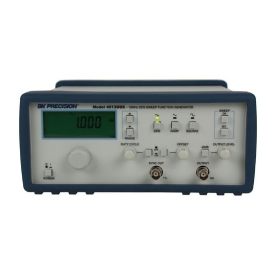
Introduction 1.1 SCOPE This manual contains installation instructions, test procedures, operation procedures and troubleshooting information required to operate, test and maintain the Model 4013DDS Function Generator. 1.2 DESCRIPTION The Model 4013DDS is a versatile, high performance function generator. Implemented using advance digital technologies based on DDS topology, the units generates superb quality waveforms with high precision and stability. -
Page 6: Inputs And Outputs
Model 4013DDS - Instruction Manual f requencies can be independently adjusted and the sweep rate can be set f rom 100ms to 30s. 1.3.3 Frequency Characteristics RANGE.............0.1 Hz to 12 MHz f or Sine and Square wav ef orms. To 1 MHz f or Triangle wav ef orms. -
Page 7: Technical Support
Installation 2.1 INTRODUCTION This section contains installation information, power requirements and an acceptance check for the Model 4013DDS Function Generator. 2.2 MECHANICAL INSPECTION This instrument was carefully inspected before shipment. Upon receipt, inspect the instrument for damage that might have occurred in transit. If there is damage due to shipping, file a claim with the carrier who transported the unit. -
Page 8: Power Requirements
The instrument includes a front feet tilt mechanism for optimum panel viewing angle. 2.4 POWER REQUIREMENTS The Model 4013DDS can operate from 115/230 Vac, 50/60Hz. The maximum power consumption is less than 25VA. CAUTION: Before connecting the line cord to the AC mains, check the rear panel AC line voltage indicator. -
Page 9: Operating Instructions
With the set up of 2.7.1, push the offset control. Rotate the offset knob from full CCW to full CW and observe a waveform change from negative to positive level. The maximum DC plus peak is limit to ±10V (un-terminated) or ±5V (50 ohms terminated). 2.7.3 Frequency Connect a counter to the instrument output. -
Page 10: Instrument Inputs And Outputs
Model 4013DDS - Instruction Manual -20dB – Attenuates the amplitude of the selected output waveform by 20-dB. DUTY CYCLE ON/OFF – Enables operation of the variable duty cycle function. DUTY CYCLE – Adjusts, after pressing the pushbutton, the duty cycle of the Square waveform, when selected. -
Page 11: First Time Operation
3.4 FIRST TIME OPERATION The following exercise will familiarize the operator with most functions of the Model 4013 function generator. Preset the controls as follows: WAVEFORM ....SINE DUTY CYCLE ....OFF OFFSET ......OFF ATTENUATOR....OFF AMPLITUDE ....CENTERED Connect a 50 coaxial cable, terminated into a 50 feedthrough, to the vertical input of an oscilloscope (set vertical to 2V/Div and horizontal to 1 ms/Div). -
Page 12: Sweep Operation
Model 4013DDS - Instruction Manual DC voltage appears at the main output by pushing the OFFSET ON button. By rotating the OFFSET control knob from CCW to CW, the output level and polarity are changed from negative to positive. This level is also controlled by the output attenuator. DC offset is achieved by adding the above DC output to any of the output waveforms selected by pressing the function buttons.
Need help?
Do you have a question about the 4013DDS and is the answer not in the manual?
Questions and answers