Bentone BG 450-2 Installation And Maintenance Instruction
Hide thumbs
Also See for BG 450-2:
- Installation and maintenance instruction (52 pages) ,
- Installation and maintenance instruction (48 pages) ,
- Installation and maintenance instruction (52 pages)

Subscribe to Our Youtube Channel
Related Manuals for Bentone BG 450-2


Summary of Contents for Bentone BG 450-2
- Page 1 178 145 76-3 P93783 2023-02-23 Providing sustainable energy solutions worldwide Installation- and maintenance instruction BG 450-2 BP230UVFR-S4 MB-ZRDLE 412 Translation of the original instructions.
- Page 2 1~230V 1,0A 50Hz IP 20 Motor supply MADE IN SWEDEN BY 1. Manualer på övriga språk 1. Manuals in other languages 1. Manualer på andre sprog 2. www.bentone.com\ 2. www.bentone.com\ 2. www.bentone.com\ nedladdning eller scanna download or scan QR-code. download eller scan QR-koden.
-
Page 3: Table Of Contents
Control of combustion .............. 24 7.4 Setting the air pressure switch ..........25 Technical data ...............6 7.5 Setting the gas pressure switch, min........26 Dimensions BG 450-2 ..............6 Settings Damper motor, 2-stage ..........27 Capacity range ................7 Gas categories, approved gases ..........7 Gas valve, MultiBloc ZRDLE 405-415..B07 .....28 2.4 Technical specification .............. -
Page 4: General Information
Make sure that the burner is suitable for the application (see Technical • Data). All components must be installed without being bent, twisted or • subjected to mechanical or thermal forces that affect components. 172 515 01-2 2021-10-05 Bentone... -
Page 5: What To Do If You Smell Gas
Prevent open fl ames or sparking, e.g. do not turn lights on or off, do • not use any electrical appliances or mobile phones. • Evacuate the building. Notify the installer or gas supplier of the problem so that it can be • rectifi ed. Bentone... -
Page 6: Technical Data
The burner is intended for: Operation in installations according to EN 303 and EN 676. • Fuels: Natural gas H, E, L, LL. • LPG, Butane and Propane. • Dimensions BG 450-2 øB øC Flame tube Flame tube Flame tube Length of flame tube... -
Page 7: Capacity Range
20 mbar 2E(R)B 20 mbar Technical specification Measurements according to EN 15036-1:2006 BG 450-2 Alt.1 The noise level of the burner can be Main supply 230V, 1~, 5.0A, 50Hz, IP20 reduced by equipping the burner with silencer. Installation must be done so... -
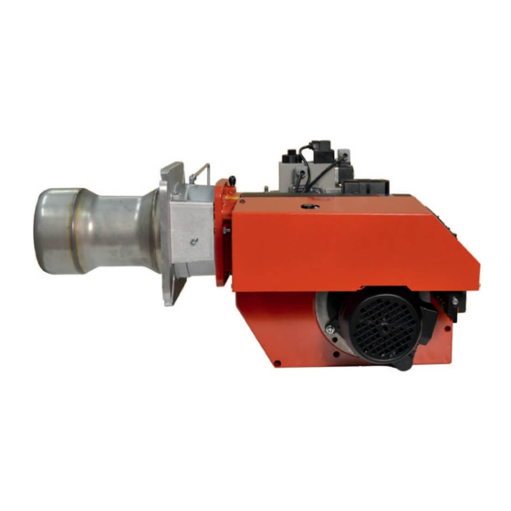
Page 8: Components
Air pressure switch Gas valve (MultiBloc) Inner assembly Ball valve Fixing fl ange Gas pressure switch, min Air damper Damper motor Transformer Air intake Contactor Reset button Ignition electrode Bruner Control Switch 0-I Ionization electrode Indication lamp, operation Connection, gas Bentone... -
Page 9: Skeleton Diagrams
Damper motor Air pressure switch Gas burner control Ventilation pipe for releasing gas Solenoid V3 Pos. 5b, 7: Components not required according to EN 676. Required over 1200 kW according to EN 676. Gas valve (MultBloc) 172 525 16 2020-10-13 Bentone... -
Page 10: Electric Equipment
Plug-in contact, stage 2, burner Plug-in contact, stage 2, boiler Time counter, Stage 2 UV-detector Solenoid valve 1 Operating switch Solenoid valve 2 Operating switch, Stage 2 Solenoid valve 3 Safety valve Control thermostat Temperature limiter 165 615 77-2 Bentone... -
Page 11: Wiring Diagram
Wiring diagram E106358 Bentone... -
Page 12: Control
Status LED shines yellow, the Fan LED fl ashes, and LEDs 2-6 show the fl ame signal strength. Each LED corresponds to 20% of the total fl ame signal. 5 lit LEDs correspond to 100% and 2 LEDs correspond to 40%. 172 615 70-2 2022-09-28 Bentone... -
Page 13: Explanation Of The Different Sequence Modes
By pressing the manual reset button on the control unit or remote reset. Note! At remote reset: maximum 5 reset attempts within a 15 min period, after which qualified personnel must examine the burner before further reset attempts are made. Bentone... -
Page 14: Burnerpro Led Fault/Lock Code Table
BurnerPro LED fault/lock code table Bentone... - Page 15 Bentone...
- Page 16 Bentone...
- Page 17 Bentone...
-
Page 18: Installation
Connection must be done in accordance with the applicable • regulations. • Connection must conform to the wiring diagram. If any electrical connection other than that recommended by Enertech is used, there is a risk of property damage and personal injury. 172 535 09-2 Bentone... -
Page 19: Handling And Lifting Instruction
Handling and lifting instruction The lifting aid are available as accessories. 172 515 29 2018-02-21 Bentone... -
Page 20: Mounting
Connect the gas line, connect the supply cable, operating and safety circuits. Before obtaining access to electrical and fuel line components all supply circuits must be disconnected. 172 515 30-2 2022-09-21 Bentone... -
Page 21: Gas Nozzle
Gas nozzle Check that the ignition electrodes are correctly set before mounting on the boiler. Natural gas Propane Biogas (UV detector) Bentone... -
Page 22: Aerating
If leaks are found during measurement, locate the source using soapy water or leak detection spray. After sealing: check the leakage of the gas fixture again. Check for leaks in the gas line. Bentone... -
Page 23: Calculation Of Gas Flow
Butan 32.25 116.09 Natural gas 29.25 Propan 24.44 88.00 Biogas 21.60 Lower calorific value H at normal conditions 15 °C and 1013 mbar, EN 676. For exact calorific value of the gas, contact the gas distributor. 172 535 72 Bentone... -
Page 24: Settings
% CO Lambda 1.2 ≈10 Natural gas 3 - 5 11.9 ≈11.5 Propane 3 - 5 13.9 ≈11.5 Butane 3 - 5 14.1 Liquefi ed ≈11 3 - 5 13.8 petroleum gas Biogas 3 - 5 172 515 32-2 2022-09-28 Bentone... -
Page 25: Setting The Air Pressure Switch
Measure and note the lowest air pressure in the entire work area. Set the air pressure switch to about 10-15% lower than the lowest noted pressure. Test run the burner and check the function in the entire work area. Refi t protective cover. Bentone... -
Page 26: Setting The Gas Pressure Switch, Min
When the gas pressure switch stops the burner, the measured value must approximately correspond to the setting on the gas pressure switch. Open ball valve. Remove manometer and close measuring socket. Refi t protective cover. Check gas tightness. Bentone... -
Page 27: Settings Damper Motor, 2-Stage
≈11.5 Butane 3 - 5 14.1 Liquefi ed ≈11 3 - 5 13.8 petroleum gas Biogas 3 - 5 Solenoid valve High load (black) High load (red) Low load (orange) Closed air damper (blue) Release button 172 515 14-3 2022-10-27 Bentone... -
Page 28: Gas Valve, Multibloc Zrdle 405-415
Test point connection G 1/8 downstream of valve 1, possible on both sides Electrical connection for valves (DIN EN 175 301- 803 connector). Outlet flange Electrical connection for valves V2 Test point connection M4 down stream of valve 2 Gas flow direction 172 525 18 2020-10-16 Bentone... -
Page 29: Mounting Closed Position Indicator (Cpi)
Rotate setting screw C to ” + ” until switching point is reached. Then rotate the setting screw by another scale division. Check function by activating the valve. Re-set switching point Turn setting screw C back in arrow direction ”–” to the stop; proceed as described in 7. Bentone... -
Page 30: Flow Adjustment 2-Stage Design
Turn the adjustment knob d (use the protective cover as a tool) to the desired opening speed. Turn to the right = opening speed is reduced Turn to the left = opening speed is increased Adjustment of main valve damper z: under cap Bentone... -
Page 31: Service
Replacement upon fault detection Gas pressure switch 10 years 250,000 starts Safety blow-off system 10 years Damper motor 500,000 starts Contactor 10 years 500,000 starts The burner and its components must be recycled according to applicable regulations. 172 615 88-2 2022-09-08 Bentone... -
Page 32: Combustion Device
Switch on the main power and open the fuel supply. Start burner and check/adjust combustion. Check for leaks in the gas line. When servicing/replacing components that affect combustion, flue gas analysis and soot test must be carried out following installation. 172 615 16-2 2022-09-23 Bentone... -
Page 33: Air Damper
Fit the intake grille. Slide burner together and lock with screws (D) and nut (C). Switch on the main power and open the fuel supply. Start burner and check/adjust combustion. 172 625 03 2022-09-23 Bentone... -
Page 34: Replacement, Damper Motor Air
Refi t the damper motor and mounting plate, ensuring that the damper shaft and control arm are correctly connected. Connect the damper motor cable. Switch on the main power and open the fuel supply. Start burner and check/adjust combustion. 172 625 04 2022-09-23 Bentone... -
Page 35: Fan
Refi t the parts. Switch on the main power and open the fuel supply. Start burner and check/adjust combustion. When servicing/replacing components that aff ect combustion, fl ue gas analysis and soot test must be carried out following installation. 172 625 09 Bentone... -
Page 36: Vibrations
• Check tightness of fasteners. Check fan wheel for damage and contamination (replace if necessary). • Check motor shaft and bearings. If they are worn, replace the motor. • Use screw to attach the vibration sensor. 172 625 05 2022-09-23 Bentone... -
Page 37: Flame Monitoring And Ionisation Current Check
Status LED shines yellow, the Fan LED flashes, and LEDs 2-6 show the flame signal strength. Each LED corresponds to 20% of the total flame signal. 5 lit LEDs correspond to 100% and 2 LEDs correspond to 40%. 172 615 69 20-10-15 Bentone... -
Page 38: 9.10 Replacement Of Electrical Components
Switch on the main power and check the operation of the new component. Start burner and check/adjust combustion. When servicing/replacing components that affect combustion, flue gas analysis and soot test must be carried out following installation. 165 105 11-3 Bentone... -
Page 39: 10. Handing Over Of The Installation
Instruct the persons in charge of the operation on the service and • maintenance of the installation and what to do should any troubles occur. Inspection and service must be carried out by authorized personnel. • Review and service should be performed by authorised personnel only. 172 615 04-2 Bentone... -
Page 40: 11. Troubleshooting
Contact an electrician. Voltage lower than 185V. Ignition electrodes disrupting ionisation current. Adjust ignition electrodes. Re-polarise the transformer. Poor earth connection. Ensure adequate earth connection. Check wiring diagram and change accordingly. Phase and neutral swapped around. 172 615 06 2018-01-10 Bentone... - Page 41 Flame at incorrect angle due to combustion head out of position. Condensation build up in boiler and chimney: Raise the flue gas temperature by increasing gas volume Insulate Flue gas temperature too low or gas volume too low. the chimney. Bentone...
-
Page 42: 12. Service- And Inspection Protocol
12. Service- and inspection protocol Installation Boiler Efficiency kW: Name: Type: Address: Burner Efficiency kW: Type: Installed by: Date: Date gas/h Efficiency Governor Fluegas Ionisation Pressure temp current Fire Chimney room Measure- °C µ A ment Before After mbar mbar Small Flame Large Flame... - Page 43 EU Declaration of conformity Bentone Gas Burners Certifi cate No. Certifi cate No. Type: Type: BFG 1 CE-0123CT1269 BG 550 CE-0123CT1326 STG 120 CE-0123CT1270 BG 650 CE-0123CT1348 STG 146 CE-0123CT1281 BG 700 CE-0123CT1359 BG 300 CE-0123CT1292 BG 800 CE-0123CT1360 BG 400...
- Page 44 UK Declaration of conformity Bentone Gas Burners Type: BFG 1 BG 300 BG 550 BG 800 STG 120 BG 400 BG 650 BG 950 STG 146 BG 450 BG 700 This declaration of conformity is issued under the sole responsibility of the manufacturer.
- Page 48 Enertech AB. P.O Box 309, SE-341 26 Ljungby www.bentone.com...
Need help?
Do you have a question about the BG 450-2 and is the answer not in the manual?
Questions and answers