
Related Manuals for Kuppersbusch EKI6842.1F


Summary of Contents for Kuppersbusch EKI6842.1F
- Page 1 BEDIENUNGSANWEISUNG mit Montageanweisungen Instructions for use and installation Instructions d’utilisation et d’installation EKIF6842.1 EKI6842.1F EKI6842.1ED...
-
Page 2: Table Of Contents
Dear customer, Thank you for having chosen a KÜPPERSBUSCH induction hob. In order to install properly your appliance and to make the best use of it, please read this entire instruction manual carefully. SUMMARY SAFETY ............................21 ...................... 21 RECAUTIONS BEFORE USING ........................ -
Page 3: Safety
SAFETY Precautions before using Unpack all the materials. The installation and connecting of the appliance have to be done by approved specialists. The manufacturer cannot be responsible for damage caused by building-in or connecting errors. To be used, the appliance must be well-equipped and installed in a kitchen unit and an adapted and approved work surface. -
Page 4: Precautions Not To Damage The Appliance
Precautions not to damage the appliance Raw pan bottoms or damaged saucepans (not enamelled cast iron pots,) may damage the ceramic glass. Sand or other abrasive materials may damage ceramic glass. Avoid dropping objects, even little ones, on the vitroceramic. ... -
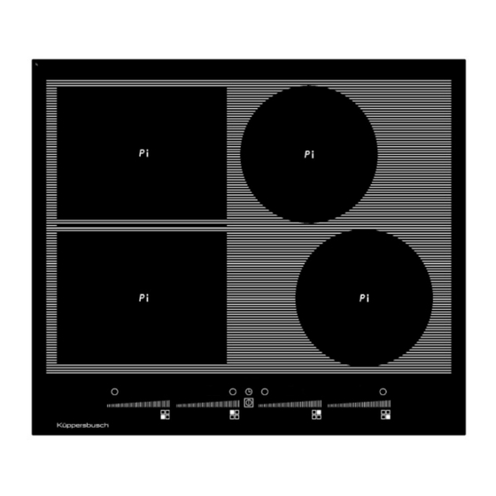
Page 5: Description Of The Appliance
Front left 220x180mm 2100 W 2600/3700 W 100 mm EKIF6842.1 Rear left 220x180mm 2100 W 2600/3700 W 100 mm EKI6842.1F 7400 W Rear right Ø180mm 1850 W 2300/3000 W 100 mm EKI6842.1ED Front right Ø180mm 1850 W 2300/3000 W 100 mm * Average measured power. -
Page 6: Ventilation
Ventilation The cooling system is fully automatic. The cooling fan starts with a low speed when the heat created by the electronic system reaches a certain level. The ventilation starts its high speed when the hob is intensively used. The cooling fan reduces its speed and stops automatically when the electronic circuit is cooled enough. -
Page 7: "Slider" Zone: To Set Power And Timer Values
“SLIDER” zone: to set power and timer values The slider works like a touch key. Once your finger is placed onto the slider, you can slide to the right hand or to the left hand side, in order to adjust the displayed value. As soon as the expected value has been reached, you can remove your finger from the slider. -
Page 8: Residual Heat Indication
Residual heat indication After the switching off of a heating zone or the complete stop of the hob, the heating zones are still hot. This is indicated by displaying [ H ] symbol. The symbol [ H ] disappears when the heating zones may be touched safely. As long as the residual heat indicators are on, don’t touch the heating zones and don’t put any heat sensitive object on them. -
Page 9: Timer
Timer The timer is able to be used simultaneously with all heating zones and this with different time settings (from 1 up to 99 minutes) for each heating zone. Setting and modification of the cooking time : Action Control panel Display Slide on the “SLIDER“... -
Page 10: Automatic Cooking
Automatic cooking All the cooking zones are equipped with an automatic cooking device. The cooking zone starts at full power for a certain time, and then reduces automatically its power to the pre-selected level. Start-up : Action Control panel Display slide on the “SLIDER“... -
Page 11: Memory Function
Memory Function After switching off the hob [ ], it is possible to recall the last settings. cooking stages of all cooking zones (Booster) minutes and seconds of programmed cooking zone-related timers Automatic cooking Keep warm function The recall procedure is following: ... -
Page 12: Control Panel Locking
Control panel locking To avoid accidentally activating or interfering with the settings of the cooking zones, for instance when cleaning, the control panel can be locked (with exception of the On/Off key [ Action Control panel Display Locking the hob Press on [ lock key ] 6s locking light blinkt Unlock the hob... -
Page 13: Cooking Advices
COOKING ADVICES Pan quality Suitable materials: steel, enamelled steel, cast iron, ferromagnetic stainless-steel, aluminium with ferromagnetic bottom Not suitable materials: aluminium and stainless-steel without ferromagnetic bottom, cupper, brass, glass, ceramic, porcelain The cookware manufacturers usually specify whether their products are suitable to induction. To check if pans are compatible: ... -
Page 14: Examples Of Cooking Power Setting
Examples of cooking power setting (the values below are indicative) 1 to 2 Melting Sauces, butter, chocolate, gelatine Reheating Dishes prepared beforehand 2 to 3 Simmering Rice, pudding, sugar syrup Defrosting Dried vegetables, fish, frozen products 3 to 4 Steam Vegetables, fish, meat 4 to 5 Water... -
Page 15: What To Do In Case Of A Problem
WHAT TO DO IN CASE O WHAT TO DO IN CASE OF A PROBLEM The hob or the cooking zone doesn’t start e cooking zone doesn’t start-up: The hob is badly connected on the electrical network. The hob is badly connected on the electrical network. ... -
Page 16: Installation Instructions
(3). Aeration Fitting - installing: Cut out sizes of the worktop: EKIF6842.1 598 mm 518 mm 560 mm 490 mm 48 mm EKI6842.1F 600 mm 520 mm 560 mm 490 mm 48 mm EKI6842.1ED... -
Page 17: Electrical Connection
Ensure that there is a distance of 40 mm between the hob and the wall or sides. The hobs are classified as “Y” class for heat protection. Ideally the hob should be installed with plenty of space on either side. There may be a wall at the rear and tall units or a wall at one side. - Page 18 The electrical circuit must be separated from the network by adapted devices, for example: circuit breakers, fuses or contactors. If the appliance is not fitted with an accessible plug, disconnecting means must be incorporated in the fixed installation, in accordance with the installation regulations. ...
Need help?
Do you have a question about the EKI6842.1F and is the answer not in the manual?
Questions and answers