Table of Contents
Advertisement
Quick Links
Advertisement
Table of Contents

Subscribe to Our Youtube Channel
Related Manuals for Pramac P2200i


Summary of Contents for Pramac P2200i
- Page 1 Operator's manual Portable Generator P2200i...
- Page 2 Errors excepted. The machine on the cover may have special equipment (options). Manufacturer PR Industrial s.rl. Loc. Il Piano 53031 Casole d’Elsa (SI) - Italy Tel.: +39 0577965200 E-mail address: info@pramac.com Original operator's manual...
-
Page 3: Table Of Contents
Foreword Introduction Means of representation for this operator's manual PRAMAC representative Described machine types Identification of the machine Safety Regulations Safety information in this operator's manual Description and purpose of the machine Operational safety Operator qualifications Safety when using combustion engines... - Page 4 Basic troubleshooting 10 Disposal 10.1 Disposal of waste electrical and electronic equipment 11 Technical data 11.1 P2200i 12 Diagram 12.1 P2200i EC declaration of conformity...
-
Page 5: Foreword
This operator's manual is not a manual for extensive maintenance or repair work. Such work should be carried out by PRAMAC service or by technically trained personnel. The PRAMAC machine should be operated and maintained in accordance with this operator's manual. An improper operation or improper maintenance can pose dangers. -
Page 6: Introduction
2 Introduction Introduction Means of representation for this operator's manual Warning symbols This operator's manual contains safety information of the categories: DANGER, WARNING, CAUTION, NOTICE. They should be followed to prevent danger to life and limb of the operator or damage to equipment and exclude improper service. -
Page 7: Pramac Representative
This symbol is used for lists. PRAMAC representative Depending on your country, your PRAMAC representative is your PRAMAC service, your PRAMAC affiliate or your PRAMAC dealer. You can find the addresses in the Internet at WWW.PRAMAC.COM The address of the manufacturer is located at the beginning of this operator's manual. -
Page 8: Safety Regulations
3 Safety Regulations Safety Regulations Safety information in this operator's manual This operator's manual contains safety regulations in the categories: DANGER, WARNING, CAUTION, NOTE and COMMENT. These are to be followed in order to reduce the danger of injury, damage to equipment or improper service. This is a safety warning symbol that warns against possible danger of injury. -
Page 9: Description And Purpose Of The Machine
3 Safety Regulations Description and purpose of the machine This machine is a portable power source. The portable generator from PRAMAC consists of a frame, which includes a fuel tank, a gasoline engine, a control panel and an electrical alternator. The control panel contains controls and bushings. -
Page 10: Operational Safety
3 Safety Regulations Operational safety DANGER Carbon monoxide. The application of a generator in buildings can LEAD TO DEATH WITHIN MINUTES. The exhaust fumes from the generator contain carbon monoxide (CO). This is an invisible odorless poison. If the exhaust fumes of the generator can be smelled, CO is being inhaled. -
Page 11: Operator Qualifications
3 Safety Regulations Connection prerequisites The following prerequisites are to be met to connect the generator to the building's mains supply. The generator must meet the prerequisites with regard to performance, voltage and frequency of the equipment. The generator must be disconnected from the electric power supply. ... - Page 12 3 Safety Regulations NEVER overload generator. The total amperage of the parts connected to the generator may not exceed the output limit. NEVER operate the machine in snow, rain or standing water. NEVER allow untrained personnel to operate or maintain the generator. Familiarize yourself with the operation and shutdown before starting the generator.
-
Page 13: Safety When Using Combustion Engines
3 Safety Regulations Safety when using combustion engines WARNING Combustion engines pose a particular danger during operation and when refueling. Failure to follow the warning notices and safety standards can lead to serious injury or death. Read and always observe the warning notices in the operator's manual of the engine and the safety instructions below. -
Page 14: Service Safety
3 Safety Regulations Safety when refueling When refueling the machine: Immediately wipe away any spilled fuel. Fill the fuel tank in a well-ventilated area. Reattach the fuel tank cap after refueling. Do not smoke. Do not refuel hot or running engines. ... - Page 15 ALWAYS keep fuel lines in a good condition and connected correctly. Leaking fuel and gases are highly explosive. If spare parts are required for this machine, only use parts from PRAMAC or parts that match the original exactly in terms of dimensions, model, intensity and material.
-
Page 16: Safety And Information Labels
4 Safety and Information labels Safety and information labels There are labels on your equipment that contain important information and safety instructions. Keep all labels legible. Replace missing or illegible labels. The item numbers on the labels can be found in the parts book. Item Label Description... -
Page 17: Standard Package
5 Standard package Standard package The standard package includes: Equipment. Operator's manual. CE declaration... -
Page 18: Lifting And Transporting
6 Lifting and transporting Lifting and transporting Lifting the machine This compact generator is heavy enough to cause injury in the event of incorrect hoisting technology. Observe the following instructions to lift the generator: Do not try to lift the generator without help. Use suitable lifting bars e.g. loops, chains, twisting hooks, ramps or car jacks. -
Page 19: Operation
Check the machine and its components for damage. Do not operate the machine if you find visible damage! Ask the PRAMAC dealer for advice at once. Check whether all of the parts belonging to the machine have been delivered and whether all loose parts and fasteners are present. -
Page 20: Power Requirements
The "General power requirements for starting" information only applies as a general guideline to assist you in determining the power requirements. The nearest PRAMAC dealer, tool manufacturer can help you if you have questions. NOTE: Do not exceed the specified current limit at any plug receptacle. -
Page 21: Performance Loss With High Altitude Application
7 Operation Performance loss with high altitude application Generators run differently due to altitude and temperature differences. Unmodified internal combustion engines have reduced performance at high altitudes due to the lower air pressure. This means less performance and therefore a reduced power exploitation. -
Page 22: Ground
7 Operation Ground CAUTION The mid-point (neutral) conductor of this equipment is not grounded. Do not drive the PE rod into the ground under normal operating conditions. Refer to the local regulations if the equipment is intended to power a building or similar system. -
Page 23: Use Of Extension Cables
7 Operation Use of extension cables A loss of power takes place when connecting electrical equipment or a tool to the generator with an extension cable — the longer the cable, the greater the loss of power. This means that less voltage is conveyed to the electrical equipment and the input current is increased or the performance is reduced. - Page 24 7 Operation Table for extension cable minimum size Extension cable minimum size 230V/1~/50Hz 400V/3~/50Hz Length in m Length in m Ampere - performance variable Cross-section surface in mm Diagram for extension cable minimum size...
-
Page 25: Control Panels
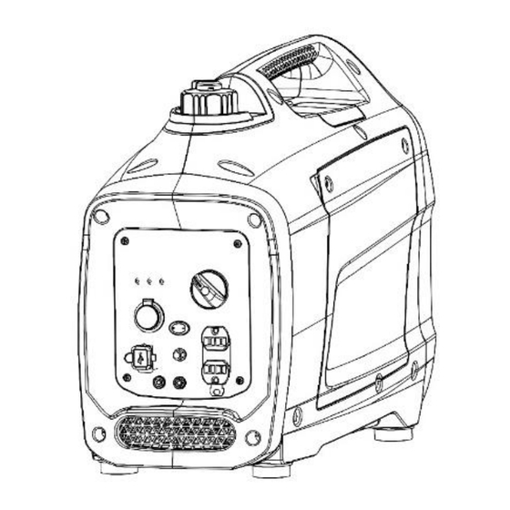
7 Operation Control Panels Oil Warning Light Overload Indicator Light AC Pilot Light DC Outlets USB Outlets DC breaker AC Outlets : this socket is only corresponding to a market, the different laws and regulations according to the sales area changes corresponding to the socket. Ground Terminal Parallel Outlets 10. -
Page 26: Control Functions
7 Operation Control Functions Throttle Throttle When the Throttle switch is in the “I” position the throttle controls the engine speed according to the connected electrical load. The results are better fuel consumption and less noise. When the switch is in the “O” position the engine runs at 4,500 rpm regardless of the electrical load. - Page 27 7 Operation NOTE: The Overload Alarm may come on for a few seconds when first using electrical devices that require a large starting current, such as a compressor, pump, or refrigerator. This is normal behavior it is not a malfunction. Low Oil Alarm (Red) When the engine oil falls below the required level the Low Oil Alarm will come on and the engine will stop automatically.
- Page 28 7 Operation generator. The switch should be in the “O” position when the engine is not running and when storing or transporting the unit. NOTE: The Off / Run / Choke switch helps to prevent stale fuel from remaining in the carburetor while storing or transporting the unit.
- Page 29 NOTE: Do not disconnect any parallel kit connections once the units are running Start both units per starting instructions. Once the green output indicator illuminates, devices can be connected and turned on using the parallel kit outlet. Follow Stopping the engine instructions NOTE: Only use Pramac approved parallel kit...
-
Page 30: Before Starting
7 Operation 7.10 Before starting DANGER Carbon monoxide. The application of a generator in buildings can LEAD TO DEATH WITHIN MINUTES. The exhaust fumes from the generator contain carbon monoxide (CO). This is an invisible odorless poison. If the exhaust fumes of the generator can be smelled, CO is being inhaled. -
Page 31: Starting The Engine
7 Operation Using the funnel (provided) fill with 0.4 L of SAE 10W-30 or 10W-40 (provided) (see figure 3). See figure 4 for proper oil level. (Figure 4) Replace oil filler cap and secure side panel with screws. Recommended engine oil: YAMALUBE4(10W-40) SAE10W-30 or 10W-40 SAE #30... -
Page 32: Stopping The Engine
7 Operation DO NOT connect any electrical devices to the outlets on the generator before starting the engine. Turn the Economy Throttle switch "O" You may turn the Economy Throttle switch to "I" once the engine is started and a steady idle is achieved, (below 0°(32°F)/5mins, below 5°C(41 °F)/3mins.). - Page 33 7 Operation Turn the Throttle switch “O”. Turn the Off / Run / Choke switch to “O”.
-
Page 34: Maintenance
8 Maintenance Maintenance Period maintenance schedule The following table contains the basic maintenance jobs for the machine. Jobs selected with a check mark can be performed by the operator. The jobs marked with a small box require special training and special equipment. Daily After the Every 3... -
Page 35: Engine Oil Replacement
8 Maintenance Engine Oil Replacement Initial replacement of the engine oil is after one month or 20 hours of operation. Place the generator on a level surface and warm up the engine for several minutes. Then stop the engine and turn the Off / Run / Choke switch to "O" and the Fuel Tank Cap Air Vent knob to "OFF". -
Page 36: Air Filter Maintenance
8 Maintenance Air Filter Maintenance Should be performed every 6 months or 100 hours. The air filter may need to be cleaned more frequently when using in unusually wet or dusty areas. Remove the screw and then remove the cover. Remove the bolt and then remove the air filter case cover. -
Page 37: Fuel Filter Maintenance
8 Maintenance Remove the carbon deposits on the muffler screen and spark arrester using a wire brush. Use wire brush lightly to avoid damaging the muffler screen or spark arrestor. Check the muffler screen and spark arrester replace them if damaged. Install the spark arrester. -
Page 38: Spark Plug
8 Maintenance Spark plug See image below Clean or replace the spark plug as needed. See engine manual. WARNING The exhaust will become very hot during operation and also remains hot for a while after the engine is switched off. Never touch a hot exhaust. Comment: See the technical data for the recommended spark plug and spark plug air gap. - Page 39 8 Maintenance Turn the fuel tank cap air vent knob to “ON” (where available) and Off / Run / Choke switch to "I" Start the engine and let it run until it stops. Duration of the running engine depends on the amount of the fuel left in the tank. Remove the screws, and then remove the cover.
-
Page 40: Basic Troubleshooting
9 Basic troubleshooting Basic troubleshooting Problem / symptom Cause / remedy Engine switch is in the "Start" position. Check the following if the engine does Fuel cock is open. not start: Fuel is replenished. Choke lever is in the correct position. The choke should be closed when starting a cold engine. -
Page 41: Disposal
10 Disposal Disposal 10.1 Disposal of waste electrical and electronic equipment Professional disposal of this machine avoids negative effects on human health and the environment, helps with the targeted treatment of pollutants and makes it possible to recycle valuable raw materials. For customers in EU countries This machine is not affected by the European directive for old electrical and electronic equipment (Waste Electrical and Electronic Equipment (WEEE)). -
Page 42: Technical Data
12 Glossary Technical data 11.1 P2200i Designation Unit P2200i MAX Power Cont. Operating Power Length Width Height Weight Engine Combustion method Four-stroke Cooling Air cooling Cylinders Displacement Fuel type Gasoline Fuel consumption@75% 0.75 Mixture preparation Carburetor Tank capacity Max. oil filling 0.35... -
Page 43: Diagram
13 Diagram Diagram 12.1 P2200i... -
Page 44: Ec Declaration Of Conformity
Here below a fac-simile of CE declaration. Original Ce declaration is provided with the rest of documents as for point 5. Fac-simile of CE Declaration of conformity...
Need help?
Do you have a question about the P2200i and is the answer not in the manual?
Questions and answers