Table of Contents
Advertisement
Installation, Operation, and Maintenance
Variable Speed Air Handlers
Convertible 2 — 5 Ton
TAMXB0A24V21DB
TAMXB0B30V31DB
TAMXB0C36V31DB
TAMXB0C42V41DB
TAMXB0C48V41DB
TAMXB0C60V51DB
The Diagnostics Mobile App is available by scanning a
QR code located inside this unit or by searching for the
Link Diagnostics App in your App Store.
Only qualified personnel should install and service the equipment. The installation, starting up, and servicing of heating, ventilating, and air-conditioning
equipment can be hazardous and requires specific knowledge and training. Improperly installed, adjusted or altered equipment by an unqualified person
could result in death or serious injury. When working on the equipment, observe all precautions in the literature and on the tags, stickers, and labels that
are attached to the equipment.
July 2023
N N o o t t e e : : "Graphics in this document are for representation only. Actual model
may differ in appearance."
N N o o t t e e : : For use with BAYEA series heaters ONLY.
N N o o t t e e : : This unit can be used in Link Communicating mode or 24 volt mode.
N N o o t t e e : : Need to use Diagnostics App to configure blower delays and
accessories etc., in 24 volt mode.
S S A A F F E E T T Y Y W W A A R R N N I I N N G G
1 1 8 8 - - G G J J 8 8 9 9 D D 1 1 - - 1 1 F F - - E E N N
Advertisement
Table of Contents
Troubleshooting

Related Manuals for Trane TAMXB0A24V21DB


Summary of Contents for Trane TAMXB0A24V21DB
- Page 1 Installation, Operation, and Maintenance Variable Speed Air Handlers Convertible 2 — 5 Ton TAMXB0A24V21DB TAMXB0B30V31DB TAMXB0C36V31DB TAMXB0C42V41DB TAMXB0C48V41DB TAMXB0C60V51DB N N o o t t e e : : “Graphics in this document are for representation only. Actual model may differ in appearance.”...
- Page 2 SAFETY SECTION AIR HANDLERS I I m m p p o o r r t t a a n n t t — This document contains a wiring W W A A R R N N I I N N G G diagram, a parts list, and service information.
-
Page 3: Table Of Contents
Table of Contents Installer Guide Notes ..... . . 4 Button Press AHC Configuration Method: Method #2......42 Unit Design. -
Page 4: Installer Guide Notes
Installer Guide Notes A A L L L L P P h h a a s s e e s s o o f f t t h h i i s s i i n n s s t t a a l l l l a a t t i i o o n n m m u u s s t t c c o o m m p p l l y y w w i i t t h h N N o o t t e e : : Duct heaters cannot be applied with this air N N A A T T I I O O N N A A L L , , S S T T A A T T E E a a n n d d L L O O C C A A L L C C O O D D E E S S ! ! handler. -
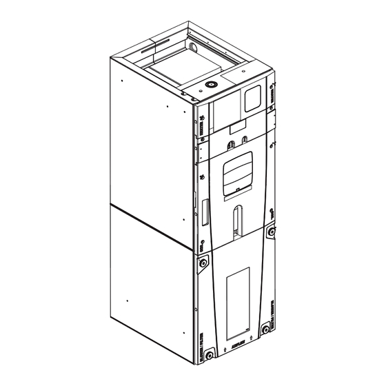
Page 5: Unit Design
Unit Design Table 1. Cabinet Penetration Important: Due to the unique design of this unit, which allows the electrical wiring to be routed within the insulation, do not screw, cut, or otherwise puncture the unit cabinet in any location other than the ones illustrated. Important: Under no conditions should metal strapping be attached Screws are allowed up to 3- 3/4”... - Page 6 U U n n i i t t D D e e s s i i g g n n The Coil, Line Set, and Heater panels are removed using Phillips head screws. Removal requires #3 Size Phillips Coil and Heater panels must be removed prior to removing the Line Set panel.
-
Page 7: Unit Install Preparation
Unit Install Preparation Check for damage and report promptly to the carrier any damage found to the unit. Note: If the unit must be transported in a horizontal position, it must be laid on its back (marked “REAR” on carton). Note: After unit is removed from the carton, verify coil is pressurized. -
Page 8: Optional Accessories
Optional Accessories Accessory Number Description Fits Cabinet Size Electric Heater, 4kW, Breaker, 24V Control, 1 Ph BAYEAAC04BK1 A to C Electric Heater, 4kW, Lugs, 24VControl, 1 Ph BAYEAAC04LG1 A to C Electric Heater, 5kW, Breaker, 24V Control, 1 Ph BAYEAAC05BK1 A to C Electric Heater, 5kW, Lugs, 24VControl, 1 Ph BAYEAAC05LG1... -
Page 9: Optional Cabinet Disassembly
Optional Cabinet Disassembly Note: If the unit must be transported in a horizontal position, it must be laid on its back (marked “REAR” on carton). Note: To reassemble cabinet, follow the steps in reverse order. Ensure electrical connections are secure and the plug clips are engaged. Remove all four front panels. - Page 10 O O p p t t i i o o n n a a l l C C a a b b i i n n e e t t D D i i s s a a s s s s e e m m b b l l y y Slide Coil assembly out of unit using built-in coil support channels and set aside Coil Support...
- Page 11 O O p p t t i i o o n n a a l l C C a a b b i i n n e e t t D D i i s s a a s s s s e e m m b b l l y y Lift the Coil section up and away from the Blower section.
- Page 12 O O p p t t i i o o n n a a l l C C a a b b i i n n e e t t D D i i s s a a s s s s e e m m b b l l y y For extremely tight spaces where the cabinet needs to be rotated through a small opening, remove the top panel and all cross members.
-
Page 13: Placing Unit At Location
Placing Unit at Location Carry the unit to the installation location Reassembly by reversing the steps listed in Section 4 if disassembly was required. If cut, wire ties that held the sensor wiring must be replaced. Important: Under no conditions should metal strapping be attached to the unit to be used as support mechanisms for carrying or suspension purposes. -
Page 14: Unit Location Considerations
Coil and Heater H x W x D Compartment Unit Net Weight MODEL NUMBER (inches) Height * (pounds) (inches) TAMXB0A24V21DB 49.9 x 17.5 x 21.8 28.1 TAMXB0B30V31DB 55.7 x 21.3 x 21.8 33.9 TAMXB0C36V31DB 56.9 x 23.5 x 21.8 35.1 TAMXB0C42V41DB 56.9 x 23.5 x 21.8... -
Page 15: Four-Way Conversion
Four-Way Conversion To place the unit in the configuration your application requires (upflow, downflow, horizontal right, or horizontal left), simply turn the unit to that orientation. Remember to adjust the badge accordingly. Note: The air handlers are shipped from the factory suitable for four-way application. Note: Entry for low voltage connections is allowed on either side of cabinet. - Page 16 F F o o u u r r - - W W a a y y C C o o n n v v e e r r s s i i o o n n Horizontal Left Configuration Airflow Refrigerant Horizontal Left Connections...
-
Page 17: Applications
Ducted and Non-Ducted Return Applications Table 4. Non-Ducted Applications C C A A U U T T I I O O N N Supply Duct H H A A Z Z A A R R D D O O U U S S V V A A P P O O R R S S ! ! F F a a i i l l u u r r e e t t o o f f o o l l l l o o w w t t h h i i s s C C a a u u t t i i o o n n c c o o u u l l d d r r e e s s u u l l t t i i n n p p r r o o p p e e r r t t y y d d a a m m a a g g e e o o r r p p e e r r s s o o n n a a l l i i n n j j u u r r y y . -
Page 18: Additional Unit Preparation
Additional Unit Preparation Considerations For proper installation the following items must be • Consider the overall space needed when external considered prior to moving the unit to its installation accessories are used, additional height and width site: requirements may exist. •... -
Page 19: Considerations
Setting the Unit — Vertical Installation Table 6. Considerations Provide a minimum height of 14 inches for proper unrestricted airflow below the unit. Allow a minimum of 21 inches clearance in front of the air handler to permit maintenance and removal of filter. •... - Page 20 S S e e t t t t i i n n g g t t h h e e U U n n i i t t — — V V e e r r t t i i c c a a l l I I n n s s t t a a l l l l a a t t i i o o n n Table 8.
-
Page 21: Installations
Setting the Unit — Horizontal Installations Table 10. Considerations Important: Due to the unique design of this unit, which allows the Field Supplied electrical wiring to be routed within the insulation , do not Isolators screw, cut, or otherwise puncture the unit cabinet in any location other than the ones illustrated in this Installer Guide or in an approved accessory’s Installer Guide. -
Page 22: Installation
Connecting the Duct work Table 11. Duct Connection Considerations Important: Due to the unique design of this unit, which allows the electrical wiring to be routed within the insulation, do not screw, cut, or otherwise puncture the unit cabinet in any location other than the ones illustrated in this Installer Guide or in an approved accessory’s Installer Guide. -
Page 23: Refrigerant Line
Refrigerant Line Table 12. Refrigerant Line Connection Sizes Vapor Line Connection Liquid Line Connection Model TAMXB0A24V21DB TAMXB0B30V31DB TAMXB0C36V31DB TAMXB0C42V41DB TAMXB0C48V41DB TAMXB0C60V51DB Notes: This table indicates the tubing connection diameters at the indoor coil. A field supplied reducing coupling may be required. -
Page 24: Refrigerant Line Brazing
Refrigerant Line Brazing Table 13. Braze the Refrigerant Lines Heater Remove Heater, Coil, and Line Set panels. Panel Line Set Panel Coil Panel Important: Do NOT unseal coil refrigerant connection stubs until ready to make connections. Important: Heat Sensitive Sensors. The Gas Temperature Sensor must be removed or a wet rag must be wrapped around the suction line between the Sensor and the braze joint to protect it from... - Page 25 R R e e f f r r i i g g e e r r a a n n t t L L i i n n e e B B r r a a z z i i n n g g Wet Rag on Gas Temperature Sensor (GT) Important: Heat Sensitive Sensor.
- Page 26 R R e e f f r r i i g g e e r r a a n n t t L L i i n n e e B B r r a a z z i i n n g g Important: Do not open the service valves until the refrigerant lines 0350 and indoor coil leak check and evacuation are complete.
-
Page 27: Condensate Drain Piping
Condensate Drain Piping Condensate Drain Piping Considerations • Condensate drain plumbing must comply with national, state, and • Do not connect the drain line to a closed drain system. local codes. • Do not use a torch or flame near the plastic drain pan coupling. •... - Page 28 C C o o n n d d e e n n s s a a t t e e D D r r a a i i n n P P i i p p i i n n g g Install a clean-out tee in the primary drain line for future maintenance.
-
Page 29: Electrical - High Voltage
Electrical — High Voltage Table 14. High Voltage Power Supply The high voltage power supply must match the equipment nameplate. W W A A R R N N I I N N G G Power wiring, including ground wiring must comply with national, L L I I V V E E E E L L E E C C T T R R I I C C A A L L C C O O M M P P O O N N E E N N T T S S ! ! sate, and local codes. - Page 30 E E l l e e c c t t r r i i c c a a l l — — H H i i g g h h V V o o l l t t a a g g e e BLACK If an electric heater IS NOT being installed, remove the pigtail harness from the documentation pack and connect it to the plug...
- Page 31 E E l l e e c c t t r r i i c c a a l l — — H H i i g g h h V V o o l l t t a a g g e e Reinstall all panels before starting the air handler Note: After replacing all panels, loosen the Line Set Panel screws approximately 1/4 —...
-
Page 32: Electrical - Low Voltage
Electrical — Low Voltage TAMX can be used in either Link Communicating mode operation is configured from the factory with no or 24 volt mode. In Link Communicating mode, all defaults for accessories. All configurations for blower configurations are made by using the configuration delays, accessories etc., need accomplished using the menu in the User Interface (UX360) or from the Diagnostic Mobile App. - Page 33 E E l l e e c c t t r r i i c c a a l l — — L L o o w w V V o o l l t t a a g g e e For low voltage entry, drill a 1/2"...
- Page 34 E E l l e e c c t t r r i i c c a a l l — — L L o o w w V V o o l l t t a a g g e e Secure the sheathed wiring to the control pocket mounting plate using the factory supplied wire ties attached to the tabs as shown.
- Page 35 E E l l e e c c t t r r i i c c a a l l — — L L o o w w V V o o l l t t a a g g e e Table 19.
- Page 36 E E l l e e c c t t r r i i c c a a l l — — L L o o w w V V o o l l t t a a g g e e Table 20.
- Page 37 3rd party condensate switch should break the Y1-in circuit between the thermostat and AHC. Y2-out connections at outdoor unit only required for two stage units and should be capped off when not in use. Only needed for heat pump operation. X2 is necessary if not using select Trane or American Standard thermostats. 18-GJ89D1-1F-EN...
- Page 38 3rd party condensate switch should break the Y1-in circuit between the thermostat and AHC. X2 is necessary if not using select Trane or American Standard thermostats. For single speed operation, use Y1-out and cap off Y2-out wire. Only needed for heat pump operation.
- Page 39 E E l l e e c c t t r r i i c c a a l l — — L L o o w w V V o o l l t t a a g g e e Table 22. GET THE APP: The Diagnostics Mobile App can be found in your device App Store when searching for Trane Diagnostics or American Standard Diagnostics. A QR code can be scanned which sends you directly to the location: Table 23.
- Page 40 E E l l e e c c t t r r i i c c a a l l — — L L o o w w V V o o l l t t a a g g e e Table 24.
-
Page 41: Volt Mode
Replacement AHC configuration – 24 volt mode Replacement AHC boards need programmed and will not run without Method #1: configuration IN 24 Volt Mode. There are 2 ways to perform the configuration. 1 of the methods is required to get the unit running. Combining 2 or more methods will result in unwanted operation. -
Page 42: Method: Method #2
Button Press AHC Configuration Method: Method #2 Table 25. Configuration for Replacement AHC Replacement AHC will need to be configured for unit size. Airflow will be set at 400 cfm/ton based on unit size configuration. These configurations can be done through the Diagnostics Mobile App with no manual steps or can be done manually without the Diagnostics Mobile App. -
Page 43: Product Specifications
Product Specifications MODEL TAMXB0A24V21DB TAMXB0B30V31DB TAMXB0C36V31DB RATED VOLTS/PH/HZ. 200 — 230/1/60 200 – 230/1/60 200 – 230/1/60 RATINGS See O.D. Specifications See O.D. Specifications See O.D. Specifications INDOOR COIL – Type Plate Fin Plate Fin Plate Fin Rows – F.P.I. - Page 44 P P r r o o d d u u c c t t S S p p e e c c i i f f i i c c a a t t i i o o n n s s MODEL TAMXB0C42CV41DB TAMXB0C48V41DB...
-
Page 45: Tamx Air Flow Performance Table
TAMX Air Flow Performance Tables 18-GJ89D1-1F-EN... - Page 46 T T A A M M X X A A i i r r F F l l o o w w P P e e r r f f o o r r m m a a n n c c e e T T a a b b l l e e s s 18-GJ89D1-1F-EN...
- Page 47 T T A A M M X X A A i i r r F F l l o o w w P P e e r r f f o o r r m m a a n n c c e e T T a a b b l l e e s s 18-GJ89D1-1F-EN...
- Page 48 T T A A M M X X A A i i r r F F l l o o w w P P e e r r f f o o r r m m a a n n c c e e T T a a b b l l e e s s 18-GJ89D1-1F-EN...
- Page 49 T T A A M M X X A A i i r r F F l l o o w w P P e e r r f f o o r r m m a a n n c c e e T T a a b b l l e e s s 18-GJ89D1-1F-EN...
- Page 50 T T A A M M X X A A i i r r F F l l o o w w P P e e r r f f o o r r m m a a n n c c e e T T a a b b l l e e s s 18-GJ89D1-1F-EN...
-
Page 51: Heater Attribute Data
Heater Attribute Data Note: Heater size will be announced when using the resistor that is being provided with the BAYEA heater. Heater can also be configured in the UX360 User Interface or Diagnostics Mobile App. TAMXB0A24V21DB 240 Volt 208 Volt No. - Page 52 H H e e a a t t e e r r A A t t t t r r i i b b u u t t e e D D a a t t a a TAMXB0C36V31DB 9.60 32800 40.0 7.20...
- Page 53 H H e e a a t t e e r r A A t t t t r r i i b b u u t t e e D D a a t t a a TAMXB0C60V51DB 240 Volt 208 Volt No.
-
Page 54: Distance From Belly Band To Shaft Face Of Motor For Minimum Vibration
Distance from Belly Band to Shaft Face of Motor for Minimum Vibration MODEL DIM “ A “ BLOWER HOUSING 2–3/8 TAMXB0A24V21DB BELLY BAND TAMXB0B30V21DB 2–3/8 MOTOR 2–3/8 TAMXB0C36V31DB WHEEL “A” is determined per chart 2–3/8 TAMXB0C42V31DB Wheel is centered in Blower Housing 2–3/8... -
Page 55: Wiring
Wiring 18-GJ89D1-1F-EN... -
Page 56: Outline Drawing
Outline Drawing NOTE: THIS UNIT IS APPROVED FOR INSTALLATION CLEARANCES TO COMBUSTIBLE MATERIAL AS STATED ON THE UNIT RATING NAMEPLATE FLOW GAS LINE LIQ LINE Model Number CONTROL BRAZE BRAZE TAMXB0A24 49.9 39.6 14.5 17.5 14.5 24.4 TAMXB0B30 55.7 45.5 18.4 21.3 18.4... -
Page 57: Filters
Filters Table 26. Filter Considerations • A filter must be installed within the system. • A filter channel is provided in the unit at the bottom of the Blower/ Filter compartment. • For customer ease of filter maintenance, it is recommended that a properly sized remote filter grill(s) be installed for units that are difficult to access. -
Page 58: System Start Up
System Start Up Make sure all panels are securely in place and that all wiring has been properly dressed and secured. Turn on electrical power disconnect(s) to apply power to the indoor and outdoor units. Set the system thermostat to ON. System Charge Adjustments System Matched with: Subcooling... -
Page 59: Fault Reporting
Fault Reporting The Air Handler Control (AHC) will show active faults and store S1 BLE historical faults in 24 volt mode. In 24 volt mode, the AHC will report Button active faults continuously and will report the last four faults stored after a power cycle of the unit. -
Page 60: Stepper Motor Tables-For Use With Low And High Superheat
Stepper Motor Tables —For use with Low and High Superheat Troubleshooting Table 1 — For use with FIG 1 Table 2— For use with FIG 2 Common Terminal to Terminal Measurement Common Terminal to Terminal Measurement Gray Orange 46 ohms Brown Blue 46 ohms... -
Page 61: Unit Test Options
Unit Test Options Table 29. 24 Volt Mode: Internal test can only be triggered using the Diagnostic Mobile App. There is not a local way to run any test mode manually. Tests available from the Diagnostics Mobile App are: The monitor menu in the Diagnostic Mobile App will show important information while in test modes that prove the test is successful. -
Page 62: Sensor
ET / GT and Supply Air Temperature Sensor Table 31. Thermal Resistance and Voltage Table Volts DC at plug Volts DC at plug Volts DC at plug J3 EVAP TEMP J3 EVAP TEMP J3 EVAP TEMP THERMISTOR THERMISTOR THERMISTOR TEMP (ET) Orange to TEMP (ET) Orange to... -
Page 63: Return Air Temperature Sensor
E E T T / / G G T T a a n n d d S S u u p p p p l l y y A A i i r r T T e e m m p p e e r r a a t t u u r r e e S S e e n n s s o o r r Return Air Temperature Sensor Table 32. -
Page 64: Sequence Of Operation
Sequence of Operation T T A A M M X X can be used in either Link Communicating When a request for 2nd stage cooling is received, mode or 24 volt mode. In Link Communicating mode, the AHC sends a command to the serial all configurations are made by using the configuration communicating blower motor to run at 100 % menu in the User Interface (UX360) or from the... - Page 65 The Diagnostics Mobile App can be found in the device aid in defrosting the coil. app store when searching Trane Diagnostic or 3. After 5 minutes, the OD will be turned back on. American Standard Diagnostics or by scanning a QR code that is located on the inside of the blower door.
-
Page 66: Checkout Procedures
Checkout Procedures The final phase of the installation is the system Checkout Procedures. The following list represents the most common items covered in a Checkout Procedure. Confirm all requirements in this document have been met. ☐ All wiring connections are tight and properly secured. ☐... -
Page 67: Troubleshooting
Troubleshooting 1 & 2 1 & 2 5 & 6 5 & 6 Are both 1-2 and 5-6 ~3.2 VDC 1-OR 2-OR 3-YELL 4-YELL 5-BR 6-BR 7-BLK 8-BLK 18-GJ89D1-1F-EN... - Page 68 T T r r o o u u b b l l e e s s h h o o o o t t i i n n g g HIGH SUPERHEAT Superheat above 30F at OD unit Start Here Perform Verify that OD Verify line set is...
- Page 69 T T r r o o u u b b l l e e s s h h o o o o t t i i n n g g Troubleshooting Low Superheat Perform these steps if Superheat is less than 3°F Perform Sensor STEP 1 Check as per Service...
- Page 70 T T r r o o u u b b l l e e s s h h o o o o t t i i n n g g Troubleshooting Low Superheat - page 2 STEP 4 Replace stepper System has Correct stepper motor and retest for...
- Page 71 T T r r o o u u b b l l e e s s h h o o o o t t i i n n g g Troubleshooting Low Superheat - page 3 STEP 8 Suction pressure Perform Close drops ValveTest from...
-
Page 72: Notices
About Trane and American Standard Heating and Air Conditioning Trane and American Standard create comfortable, energy efficient indoor environments for residential applications. For more information, please visit www.trane.com or www.americanstandardair.com. The manufacturer has a policy of continuous data improvement and it reserves the right to change design and specifications without notice. We are committed to using environmentally conscious print practices.
Need help?
Do you have a question about the TAMXB0A24V21DB and is the answer not in the manual?
Questions and answers