Table of Contents
Advertisement
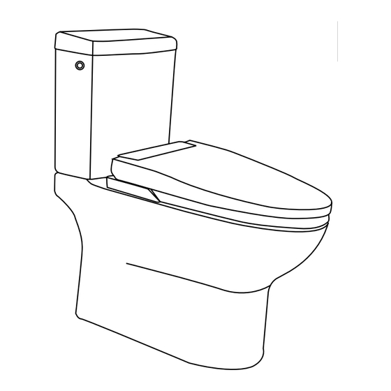
MICAH TANKLESS SMART TOILET
INSTALLATION MANUAL
SKU : 6701001
MODEL : MICAH
Flush
6"
1.28 gpf | 4.8 lpf
2x ø5/8"
ø2 1/16"
ø3 9/16"
11 7/16"
27 3/4"
15 3/8"
27 3/8"
5 15/16"
14 15/16"
21 1/4"
10 1/4"
11 5/8"
10 13/16"
6 5/16"
12"
11 7/16"
A general installation guide is provided in the YouTube link below
or through scanning the QR code below.
https://tinyurl.com/5xk4z3ms
Questions, problems, need help?
Before returning to your retailer, call our customer service department at :
1-866-839-2888
8 a.m. - 5 p.m., EST, Monday - Friday
PAGE 1
www.ovedecors.com | customerservice@ovedecors.com
Advertisement
Table of Contents

Related Manuals for OVE MICAH 6701001


Summary of Contents for OVE MICAH 6701001
- Page 1 MICAH TANKLESS SMART TOILET INSTALLATION MANUAL SKU : 6701001 MODEL : MICAH Flush 6” 1.28 gpf | 4.8 lpf 2x ø5/8” ø2 1/16” ø3 9/16” 11 7/16” 27 3/4” 15 3/8” 27 3/8” 5 15/16” 14 15/16” 21 1/4” 10 1/4” 11 5/8”...
-
Page 2: Table Of Contents
TABLE OF CONTENTS TABLE OF CONTENTS ........2 SAFETY INFORMATION ........3 POWER OUTLET ..........3 PARTS LIST ............4 TOOLS REQUIRED (not supplied) ....4 INSTALLATION ...........7 INSTALLATION OPTION#1: FOR INSTALLA- TION TO A 1/2” WATER OUTLET PIPE...10 INSTALLATION OPTION#2: FOR INSTALLA- TION TO A 3/8” SHUT-OFF VALVE....13 BATTERY USAGE SAFETY GUIDELINES ..16 BATTERY INSTALLATION .......16 FIRST TIME USE GUIDELINES .......18... -
Page 3: Safety Information
SAFETY INFORMATION CAUTION 1. Do not disassemble toilet by yourself. 2. Ensure that there is proper air flow in the room to avoid humidity buildups. 3. Ensure that the product is set more than 0.6 meter away from the bathtub. 4. -
Page 4: Parts List
PARTS LIST TOOLS REQUIRED (not supplied) Screwdriver Measuring Tape Adjustable wrench Silicone PAGE 4... - Page 5 PARTS LIST ITEM # DESCRIPTION QUANTITY PART CODE Toilet Tank Cover 99TOI0546-OU Inner Tank Shelf 99TOI0369-OU Toilet Tank 99TOI0547-OU Manual Flush Button 99TOI0366-OU Electric Flush Valve 99TOI-T4RAD575-OU Side Control Panel Water Supply Hose type 3/4”-G (pre-installed) 99TOI0118-OU Shut-off Valve (1/2-G to 3/4-G) 99TOI0322-OU Shut-off Valve Water Filter Included in #H...
- Page 6 PARTS LIST ITEM # DESCRIPTION QUANTITY PART CODE Complete Smart Seat 99TOI0544-OU Nozzle 99TOI0042-OU Ceramic Bowl 99TOI0451-OU Seal ring (wax ring) 99TOI0043-OU Remote 99TOI0515-OU Tank hardware 99TOI0365-OU 1/2”-NPT to 1/2”-G Coupling Adapter 99TOI0403-OU Reducing Valve 99TOI0406-OU Check Valve 99TOI0404-OU Large Size O-Ring Included in #S 7/8”...
-
Page 7: Installation
INSTALLATION 1.1- Remove the seat from the ceramic base. Simply pull the seat up gently. 1.2- Disconnect the electrical cords. 1.3- Install the toilet flange (not supplied) according to the manufacturer’s recommendations. 1.4- Position correctly the two fixing bolts of the toilet flange. Follow manufacturer’s recommendations. FLANGE NOT SUPPLIED PAGE 7... - Page 8 INSTALLATION 2.1- Insert the wax ring gasket under the toilet. 2.2- Position the toilet on the flange, making sure the fixing bolts are aligned with the toilet’s holes. 2.3- Using a ratchet, tightly screw the nut to the fixing bolts. 2.4- With care, re-install the seat on the ceramic base.
- Page 9 INSTALLATION 3.1- Connect the water tube: Gently, but firmly push the tube inside the hole. Re-insert the blue clip. 3.2- Tightly screw the nut to the fixing bolts. 3.3- Reconnect the three electrical cords. Make sure both ends are well aligned. 3.4- Place the shelf into the tank about 6”...
-
Page 10: Installation Option#1: For Installation To A 1/2" Water Outlet Pipe
INSTALLATION OPTION#1: FOR INSTALLATION TO A 1/2” WATER OUTLET PIPE INSTALLATION TO A 1/2” NPT THREADED WATER OUTLET PIPE It is recommended to install the smart toilet with the supplied 1/2” to 3/4” shut-off valve for best performances at low water pressure. To do so, a water outlet pipe with a 1/2” NPT Male threaded end (not supplied) must be pre-installed. - Page 11 INSTALLATION OPTION#1: FOR INSTALLATION TO A 1/2” WATER OUTLET PIPE 5.1- When connecting the fittings, it is important to properly seal all connections. Pipe Thread Sealant, also known as Pipe Dope is the best option for sealing, but Teflon Tape can also be used. Be careful not to use Plumbers Putty as it will fuse the joints permanently and future disassembly will not be possible.
- Page 12 INSTALLATION OPTION#1: FOR INSTALLATION TO A 1/2” WATER OUTLET PIPE 6.1- Remove the pre-installed Water Supply Hose (G) from the toilet by loosening and unscrewing the nut. Insert the Reducing Valve (R) as shown. Reconnect the Water Supply Hose (G) to toilet and tighten the nut. NOTE: Install the Reducing Valve (R) at the back of the toilet.
-
Page 13: Installation Option#2: For Installation To A 3/8" Shut-Off Valve
INSTALLATION OPTION#2: FOR INSTALLATION TO A 3/8” SHUT-OFF VALVE INSTALLATION TO A PRE-EXISTING 3/8” COMPRESSION SHUT OFF VALVE It is recommended to install the smart toilet with the supplied 1/2” to 3/4” shut-off valve for best performances at low water pressure. But it is possible to connect the smart toilet to an existing standard 3/8”... - Page 14 INSTALLATION OPTION#2: FOR INSTALLATION TO A 3/8” SHUT-OFF VALVE 8.1- Change the pre-installed O-ring on the Check Valve (S) to the Large Size O-ring (T). 8.2- Remove the pre-installed Water Supply Hose (G) from the toilet by loosening and unscrewing the nut. 8.3- Insert the Check Valve (S) into toilet water inlet as shown.
- Page 15 INSTALLATION OPTION#2: FOR INSTALLATION TO A 3/8” SHUT-OFF VALVE 9.1- Connect the 7/8” Ballcock to 3/4” G Bushing Adapter (U) to the toilet water inlet at the back. Screw the 3/4” G Female part of the Bushing Adapter (U) to the 3/4” G Male end of the toilet water inlet. 9.2- Connect the 7/8”...
-
Page 16: Battery Usage Safety Guidelines
BATTERY USAGE SAFETY GUIDELINES • Always purchase the correct size and grade of battery most suitable for the intended use. • Clean the battery contacts and also those of the device prior to battery installation. • Remove batteries from equipment which is not to be used for an extended period of time. •... - Page 17 BATTERY INSTALLATION In order to make sure the flushing can work in the event of a power shortage, install a durable battery inside that will power the flush valves in such events. 11.1- Remove the tank cover and the shelf. 11.2- Remove the cover from the battery enclosure.
-
Page 18: First Time Use Guidelines
FIRST TIME USE GUIDELINES 12.1- Open the shut-off valve. 12.2- Plug the toilet in the GFCI power socket. 12.3- The toilet’s blue light will start blinking. The blinking light indicates that the bidet tank is filling with water, a sensor in the toilet will stop the filling process automatically after around 1 minutes when the tank is full of water. -
Page 19: Remote Control Pairing
REMOTE CONTROL PAIRING NOTICE: To ensure good function, the remote has to be paired to the toilet after the first start-up. 13.1- Ensure the toilet is powered off (press the POWER button on the side keypad of the toilet once or twice so tha the LED Light Indicator turns off). -
Page 20: Toilet Seat Keypad Description
TOILET SEAT KEYPAD DESCRIPTION POWER Press 1 time, it will turn the toilet ON. Press 2 times, it will turn the toilet OFF. STOP: Pressing this button will stop any ongoing function. LADY BIDET / MOVE: Pressing this button will initiate the Back-&-Forth Lady Bidet Cleaning function. Press it again to change to the Static Bidet Cleaning function. After 30 seconds of use, the Air Drying function will start automatically. -
Page 21: Remote Control Button Descriptions
REMOTE CONTROL BUTTON DESCRIPTIONS REAR BIDET / MOVE: Pressing this button will initiate the Static Rear Bidet Cleaning function. Press it again to change to the Back-&-Forth Rear Bidet Cleaning function. *The REAR BIDET refers the 1 water jet function of the nozzle. LADY BIDET / MOVE: Pressing this button will initiate the Static Lady Bidet Cleaning function. - Page 22 REMOTE CONTROL BUTTON DESCRIPTIONS WATER TEMPERATURE BUTTON & INDICATOR Pressing this button will cycle through the 4 possible temperatures settings for the Bidet cleaning water jets. LIGHT OFF = Room temp / GREEN = Low / ORANGE = Medium / RED = High AIR TEMPERATURE BUTTON &...
-
Page 23: Audio Signals
AUDIO SIGNALS BEEPING SOUNDS DIRECTIONS 1X BEEP = The toilet will give out one beeping sound every time it successfully receives a command from the Remote Control. 2x BEEP = The toilet will give out two beeping sounds every time it has successfully received a command, but cannot execute it. The toilet might not be able to execute a given commant because the function is currently unavailable, or because a given function has reached its maximum or minimum setting. -
Page 24: Features
FEATURES REAR BIDET CLEANING (1 WATER JET) This function will only work if the user is sitting on the toilet. Press the REAR BIDET/MOVE button for a rear bidet cleaning. Water will spray and clean the user. Press the button again and the nozzle will move back & forth to insure the cleanest result. You can use this key feature to get the best cleaning effect. -
Page 25: Cleaning The Shut-Off Valve Water Filter
CLEANING THE SHUT-OFF VALVE WATER FILTER 19.1- Close the shut-off valve, turn clockwise. Do not take out the filter before closing the shut-off valve. 19.2- Unscrew the cap of the shut-off valve. 19.3- Clean the filter. Use a tooth brush to clean the dirt on the filter. Use a cloth to clean the dirt and deposits in the valve. Use water instead of detergent. -
Page 26: Cleaning The Bushing Filter
CLEANING THE BUSHING FILTER 20.5- Close the shut off valve. Unscrew and remove the water supply line. Unscrew and remove the 7/8” Ballcock to 3/4” G Bushing Adapter (U). 20.6- The Bushing Filter (V) is located inside the 7/8” Ballcock to 3/4” G Bushing Adapter (U). Gently remove it and gently brush with a toothbrush or similar tool to remove any residue. -
Page 27: Long Term Storage
LONG TERM STORAGE NOTICE: When leaving for a long time without using this toilet, ensure to drain all the water from the toilet. 21.1- Close shut-off valve. 21.2- Unscrew the water drain plug. 21.3- After draining all of the water, tightly screw the water drain plug back into place. BATTERY MAINTENANCE NOTICE: To ensure that the flushing function works in the event of an electricity shortage, replace the battery once a year. -
Page 28: Specification Sheet
SPECIFICATION SHEET Item Content AC 120V / 1300W / 60HZ Electric Load 1.5 m insulated power cord Electric Cord Cleaning System Adjustable pressure Rear Bidet (1 jet) Adjustable pressure Lady Bidet (5 jets) 4 Levels Water Temp Heater Capacity AC 120V / 1200W / 60HZ 0.3 L Bidet Tank Capacity Temperature safety reset protector integrated. -
Page 29: Fcc Statement
This device complies with FCC’s radiation exposure limits set forth for an uncontrolled environment. The Responsible party information: • Name: OVE Decors ULC • Address (Canada): 2800 ETIENNE LENOIR, LAVAL, QUEBEC, CANADA, H7R 0A3 • Address (USA): 500 S. Main Street, Mooresville, NC, USA, 28115 •... -
Page 30: Maintenance And Care
Limited Warranty: OVE warrants to the original retail purchaser that within a reasonable time after notification from purchaser, OVE will repair or replace the Product, or any part or component of the covered Product, distributed by OVE which is proven to the satisfaction of OVE to be defective in workmanship or materials, and which has failed during normal use and within the warranty period.
Need help?
Do you have a question about the MICAH 6701001 and is the answer not in the manual?
Questions and answers
Why is my toilet not flushing properly..the jet flush at end not working