Table of Contents
Advertisement
Quick Links
RETAIN THESE INSTRUCTIONS
FOR FUTURE REFERENCE
General
This XCZ20 outdoor air conditioner is designed for use
with HFC-410A refrigerant only. This unit must be installed
with an approved indoor air handler or coil. For AHRI Certi
fied system matchups and expanded ratings, visit
www.LennoxPros.com.
These instructions are intended as a general guide and do
not supersede local codes in any way. Consult authorities
having jurisdiction before installation.
THIS UNIT IS A INTEGRAL COMPONENT OF A SYSTEM THAT
WILL
REQUIRE
AN
S30
COMMUNICATING AIR HANDLER OR FURNACE.
S30
thermostat
XCZ20
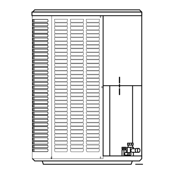
STEP 1 -- SETTING THE UNIT -- Clearances
Í Í Í Í Í Í Í Í Í Í Í Í Í
Í Í Í Í Í Í Í Í Í Í Í Í Í
Í Í Í Í Í Í Í Í Í Í Í Í Í
See NOTES
Í Í Í Í Í Í Í Í Í Í Í Í Í
Í Í Í Í Í Í Í Í Í Í Í Í Í
Í Í Í Í Í Í Í Í Í Í Í Í Í
Í Í Í Í Í Í Í Í Í Í Í Í Í
See
NOTES
Í Í Í Í Í Í Í Í Í Í Í Í Í
Í Í Í Í Í Í Í Í Í Í Í Í Í
Í Í Í Í Í Í Í Í Í Í Í Í Í
See NOTES
Í Í Í Í Í Í Í Í Í Í Í Í Í
Í Í Í Í Í Í Í Í Í Í Í Í Í
Í Í Í Í Í Í Í Í Í Í Í Í Í
NOTICE: Specific applications may require adjustment of the listed installation clearances to provide protection for
the unit from physical damage or to avoid conditions which limit operating efficiency. (Example: Snow and ice falling
on the top of the unit or installation under a deck with minimum clearances, causing recirculation of air.)
E2018 Lennox Industries Inc.
Dallas, Texas, USA
THERMOSTAT
AND
LENNOX
Communicating air
handler or furnace
See
NOTES
Control
Box
INSTALLATION
INSTRUCTIONS
Elite
Series XCZ20 Units
®
AIR CONDITIONER
507877-01
8/2018
OUTDOOR UNIT
For more in-depth information, consult the Installa
tion and Service Procedures manual available on
LennoxPros.com or through the Technical Support
department at 800-453-6669.
Improper installation, adjustment, alteration, ser
vice or maintenance can cause property damage,
personal injury or loss of life.
Installation and service must be performed by a li
censed professional installer (or equivalent) or ser
vice agency.
NOTES:
Service clearance of 30 in. must be maintained on one of the sides
adjacent to the control box.
Clearance to one of the other three sides must be 36 in.
Clearance to one of the remaining two sides may be 12 in. and the
final side may be 6 in.
A clearance of 24 in. must be maintained between two units.
48 in. clearance required on top of unit.
FIGURE 1
Page 1
PACKING LIST
WARRANTY
CERTIFICATE
CONNECTOR (1)
NOTICE !
WARNING
RAST 6-PIN
Advertisement
Table of Contents

Related Manuals for Lennox iComfort Elite XCZ20


Summary of Contents for Lennox iComfort Elite XCZ20
- Page 1 INSTALLATION E2018 Lennox Industries Inc. INSTRUCTIONS Dallas, Texas, USA Elite Series XCZ20 Units ® AIR CONDITIONER 507877-01 RETAIN THESE INSTRUCTIONS 8/2018 FOR FUTURE REFERENCE General This XCZ20 outdoor air conditioner is designed for use PACKING LIST with HFC-410A refrigerant only. This unit must be installed with an approved indoor air handler or coil.
- Page 2 STEP 1 -- SETTING THE UNIT (Contd.) -- Dimensions / Placement UNIT DIMENSIONS - INCHES (MM) SIDE VIEW TOP VIEW UNIT DIMENSIONS - INCHES (MM) Model Number XCZ20-024-230 37-1/2 (952) XCZ20-036-230 37-3/4 (908) 35-3/4 (959) XCZ20-048-230 43-3/4 (1111) XCZ20-060-230 NOTICE ! WARNING Roof Damage! To prevent personal injury, as well as damage to...
-
Page 3: Step 2 - Refrigerant Piping
STABILIZING UNIT ON UNEVEN SURFACES PLACEMENT #10 X 1/2" LONG Install unit away from windows. SELF-DRILLING SHEET METAL COIL SCREWS STABILIZING BRACKET (18-GAUGE METAL — 2" BASE PAN WIDTH; HEIGHT AS REQUIRED) #10 X 1-1/4" LONG HEX HD SCREW AND FLAT WASHER CORNER POST PLASTIC ANCHORS... - Page 4 IMPORTANT ! IMPORTANT ! If this unit is being matched with an approved line set or If unit is equipped with a crankcase heater, and outdoor indoor unit coil that was previously charged with mineral ambient temperature is below 60°F, unit should be ener oil, or if it is being matched with a coil which was manu...
- Page 5 Table 2. XCZ20 Line Set Guidelines — 51 to 150 Linear Feet in Length Preferred Maximum Vapor Line Maximum Total Maximum Linear Maximum Vapor Required Vapor Model Linear Liquid Sizes for Equivalent Length (ft) (actual) Length (ft) Riser (ft) Riser Size Lift (ft) Horizontal Runs...
- Page 6 STEP 2 -- REFRIGERANT PIPING -- Removing Existing Indoor Metering Device TYPICAL EXISTING FIXED ORIFICE TYPICAL EXISTING EXPANSION VALVE REMOVAL REMOVAL PROCEDURE PROCEDURE (UNCASED COIL SHOWN) (UNCASED COIL SHOWN) STUB END TWO-PIECE PATCH PLATE LIQUID LINE DISTRIBUTOR TUBES (UNCASED COIL ONLY) ORIFICE EXPANSION LIQUID LINE ORIFICE HOUSING...
- Page 7 STEP 2 -- REFRIGERANT PIPING -- Brazing Procedures CAP AND CORE REMOVAL CUT AND DEBUR Cut ends of the refrigerant lines square (free from nicks or dents) Remove service cap and core from and debur the ends. The pipe must remain round. Do not crimp end both the suction and liquid line service of the line.
- Page 8 STEP 2 -- REFRIGERANT PIPING -- Brazing Procedures (Continued) WRAP SERVICE VALVES To help protect service valve seals during brazing, wrap water-saturated cloths around service valve bodies and copper tube stubs. Use additional water-saturated cloths underneath the valve body to protect the base paint. FLOW NITROGEN Flow regulated nitrogen (at 1 to 2 psig) through the refrigeration gauge set into the valve stem port connection on the liquid service valve and out of the suction / vapor valve stem port.
-
Page 9: Step 3 -- Installing Indoor Expansion Valve
STEP 3 -- INSTALLING INDOOR EXPANSION VALVE This outdoor unit is designed for use in systems that include an expansion valve metering device. See the XCZ20 Product Specifications bulletin (EHB) for approved expansion valve kit match-ups and application information. The expansion valve can be installed internal or external to the indoor coil. -
Page 10: Step 4 -- Leak Test And Evacuation
STEP 4 -- LEAK TEST AND EVACUATION HIGH MANIFOLD GAUGE SET OUTDOOR UNIT TO VAPOR SERVICE VALVE NOTE - Position canister to deliver liquid refrigerant. NITROGEN HFC-410A CONNECT GAUGE SET A. Connect the high-pressure hose of an HFC-410A manifold gauge set to the vapor valve service port. NOTE - Normally, the high-pressure hose is connected to the liquid line port. - Page 11 STEP 4 -- LEAK TEST AND EVACUATION (Continued) EVACUATION HIGH CONNECT GAUGE SET NOTE - Remove cores from service valves (if not already done). Connect low side of manifold gauge set with 1/4 SAE in-line tee to vapor line service valve Connect high side of manifold gauge set to OUTDOOR MANIFOLD...
-
Page 12: Install Thermostat
STEP 5 -- ELECTRICAL -- Circuit Sizing and Wire Routing In the U.S.A., wiring must conform with current local codes and the cur IMPORTANT ! rent National Electric Code (NEC). In Canada, wiring must conform with current local codes and the current Canadian Electrical Code (CEC). If unit is equipped with a crankcase heater, it should be energized 24 hours before unit start-up to prevent com... - Page 13 STEP 5 -- ELECTRICAL -- Master Control Jumper and Terminals 7-SEGMENT DISPLAY PUSH BUTTON PUMP DOWN - WHEN UNIT IS IN PUMP DOWN MODE, Pd WILL BE DISPLAYED ON 7-SEGMENT. TO ACTIVATE PUMP DOWN MODE, THE CONTROL MUST BE IN THE IDLE STATE, AND THE PUMP DOWN JUMPER PLACED ACROSS THE TWO PUMP DOWN PINS.
- Page 14 ROUTE CONTROL WIRES Maximum length of wiring (18 gauge) for all connections on the RSBus is 1500 feet (457 meters). Wires should be color-coded, with º º a temperature rating of 95 F (35 C) minimum, and solid-core (Class II Rated Wiring). All low voltage wiring must enter unit through field-provided field-installed grommet installed in electrical inlet.
- Page 15 Charging Outdoor Control Seven-Segment Display and Push Button The XCZ20 unit is factory-charged with enough HFC-410A Information concerning the outdoor control seven-seg refrigerant to accommodate a 15-foot length of refrigerant piping. Charge should be checked and adjusted using the ment display and push button operations are available on tables provided on the charging procedure sticker on the the unit access panel and in the XCZ20 Installation and unit access panel.
- Page 16 Start-Up and Performance Checklist Customer Address Indoor Unit Model Serial Outdoor Unit Model Serial Notes: START UP CHECKS Refrigerant Type: Rated Load Amps: Actual Amps Rated Volts Actual Volts Condenser Fan Full Load Amps Actual Amps: COOLING MODE Suction Pressure: Liquid Pressure: Supply Air Temperature: Ambient Temperature:...
-
Page 17: Homeowner Information
The filter and all access panels must be in place any time the unit is in operation. If you are unsure about the Indoor Unit (Air Handler or Furnace) filter required for your system, call your Lennox dealer for A. Inspect component wiring for loose, worn or damaged assistance. - Page 18 Pour water in pans to confirm proper drainage from the I. Indoor unit inspections of gas- or oil-fired furnaces will pan through to the outlet of the pipe. Clean or replace also include inspection and cleaning of the burners as necessary. and and a full inspection of the gas valve, heat ex...
Need help?
Do you have a question about the iComfort Elite XCZ20 and is the answer not in the manual?
Questions and answers