Lennox XC14 Series Unit Information
Hide thumbs
Also See for XC14 Series:
- Engineering data (44 pages) ,
- Installation instructions manual (24 pages) ,
- Brochure & specs (4 pages)
Advertisement
Quick Links
Service Literature
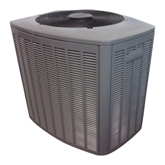
The XC14 is a high efficiency residential split−system con-
densing unit, which features a scroll compressor and
R−410A refrigerant. XC14 units are available in sizes rang-
ing from 1 1/2 through 5 tons. The series is designed for use
with an expansion valve or RFC (approved for use with
R−410A) in the indoor unit. This manual is divided into sec-
tions which discuss the major components, refrigerant sys-
tem, charging procedure, maintenance and operation se-
quence.
Information contained in this manual is intended for use by
qualified service technicians only. All specifications are sub-
ject to change.
WARNING
Improper installation, adjustment, alteration, service
or maintenance can cause property damage, person-
al injury or loss of life. Installation and service must
be performed by a qualified installer or service
agency.
WARNING
Warranty will be voided if covered equipment is re-
moved from original installation site. Warranty will
not cover damage or defect resulting from:
Flood, wind, lightning, or installation and operation
in a corrosive atmosphere (chlorine, fluorine, salt,
recycled waste water, urine, fertilizers, or other dam-
aging chemicals).
DANGER
Shock Hazard
Remove all power at disconnect
before removing access panel.
Single phase XC14 units use single-
pole contactors. Potential
exists for electrical shock resulting
in injury or death.
Line voltage exist at all components
(even when unit is not in operation).
Corp. 0704−L2
Revised 07−2008
XC14 SERIES UNITS
Operating pressures of this R−410A unit are higher
than pressures in R−22 units. Always use service
equipment rated for R410A.
General
Specifications / Electrical Data
I Application
II Unit Components
III Refrigeration System
IV Charging
V Service and Recovery
VI Maintenance
VII Wiring and Sequence of Operation
Page 1
IMPORTANT
TABLE OF CONTENTS
. . . . . . . . . . . . . . . . . . . . . . . . . . . .
. . . . . . . . .
. . . . . . . . . . . . . . . . . . . . . . . . .
. . . . . . . . . . . . . . . . . .
. . . . . . . . . . . . . . .
. . . . . . . . . . . . . . . . . . . . . . . . .
. . . . . . . . . . . . . .
. . . . . . . . . . . . . . . . . . . . . .
©2007 Lennox Industries Inc.
XC14
Page 1
Page 2
Page 4
Page 4
Page 8
Page 9
Page 21
Page 21
. .
Page 22
Advertisement

Related Manuals for Lennox XC14 Series


Summary of Contents for Lennox XC14 Series
- Page 1 XC14 Corp. 0704−L2 Revised 07−2008 Service Literature XC14 SERIES UNITS The XC14 is a high efficiency residential split−system con- densing unit, which features a scroll compressor and R−410A refrigerant. XC14 units are available in sizes rang- ing from 1 1/2 through 5 tons. The series is designed for use with an expansion valve or RFC (approved for use with R−410A) in the indoor unit.
- Page 2 SPECIFICATIONS −1 units and 030 through 060 −2 units General Model No. XC14−018 XC14−024 XC14−030 XC14−036 XC14−042 XC14−048 XC14−060 Data Nominal Tonnage Connections Liquid line o.d. − in. (sweat) (sweat) Suction line o.d. − in. 1-1/8 Refrigerant (R-410A) furnished 6 lbs. 12 oz. 7 lbs. 10 oz. 8 lbs. 0 oz. 8 lbs. 9 oz. 8 lbs. 10 oz. 10 lbs. 0 oz. 12 lbs. 0 oz. Outdoor Net face area - Outer coil...
- Page 3 SPECIFICATIONS 018, 024 −2 units & 030 through 060 −3 units General Model No. XC14−018 XC14−024 XC14−030 XC14−036 XC14−042 XC14−048 XC14−060 Data Nominal Tonnage Connections Liquid line o.d. − in. (sweat) (sweat) Suction line o.d. − in. 1-1/8 Refrigerant (R-410A) furnished 5 lbs.
- Page 4 3 -1/2, 4 and 5 ton capacities. All major components (indoor Panel shown slightly rotated to allow top tab to exit (or enter) top blower and coil) must be matched according to Lennox rec- slot for removing (or installing) panel.
- Page 5 2 − Dual Capacitor (C12) Rotate panel to vertical to fully engage all tabs. The compressor and fan in XC14 series units use perma- Holding the panel’s hinged side firmly in place, close the right−hand side of the panel, aligning the screw holes.
- Page 6 B − Compressor (B1) The scroll compressor used in all XC14 model units, is de- signed for use with R410A refrigerant and operation at high pressures. Compressors are shipped from the factory SOUND COVER charged with 3MA (32MMMA) P.O.E. oil. All XC14 compres- sors are equipped with a factory installed sound cover made of polyethylene containing a 2 inch thick batt of fiberglass in- sulation.
- Page 7 If the compressor is replaced, All units use single−phase PSC fan motors which require a run conventional Lennox cleanup practices must be used. capacitor. In all units, the condenser fan is controlled by Due to its efficiency, the scroll compressor is capable of draw- the compressor contactor.
- Page 8 A − Plumbing screws Field refrigerant piping consists of liquid and suction lines from the condensing unit (sweat connections) to the indoor evaporator coil (sweat connections). Use Lennox L15 (sweat) series line sets as shown in table 1. TABLE 1 Liquid...
- Page 9 To Close Service Valve: Ball Valve (Valve Open) 1 − Remove the stem cap with an adjustable wrench. Use Adjustable Wrench 2 − Using the adjustable wrench to keep the valve station- To open: rotate Stem Clockwise 90°. ary, use a service wrench with a hex−head extension to To close: rotate Stem Counter-clockwise 90°.
- Page 10 B − Evacuating WARNING Evacuating the system of noncondensables is critical for Fire, Explosion and Personal Safety proper operation of the unit. Noncondensables are defined Hazard. as any gas that will not condense under temperatures and Failure to follow this warning could re- pressures present during operation of an air conditioning sult in damage, personal injury or system.
- Page 11 C − Charging −1 units and 030 through 060 −2 CAUTION Polyol Ester Oil Danger of Equipment Damage. IMPORTANT Avoid deep vacuum operation. Do not use compres- sors to evacuate a system. Mineral oils are not compatible with R−410A. If oil Extremely low vacuums can cause internal arcing and must be added, it must be a polyol ester oil.
- Page 12 Units Delivered Void of Charge Pre−charge Airflow Check of Temperature Drop across Evaporator Coil (Delta−T) If the system is void of refrigerant, clean the system using the procedure described below. NOTE − Be sure that filters and indoor and outdoor coils are 1.Use nitrogen to pressurize the system and check for clean before testing leaks.
- Page 13 START: Determine how refrigerant is metered WHEN TO CHARGE? Which Warm weather best metering Can charge in colder weather device? CHARGE METHOD? Determine by: Metering device type Outdoor ambient temperature REQUIREMENTS: Sufficient heat load in structure Above 65ºF Below 65ºF Above 40ºF (18ºC)? (18ºC)?
- Page 14 - Check Liquid and Vapor line pressures START: Measure outdoor ambient temperature - Compare unit pressures with Normal Operating Pressures table 4, page 15. ABOVE (Table 4 is a general guide. Expect minor pressures USE WEIGH-IN METHOD DO NOT CHARGE UNIT Above or variations.
- Page 15 TABLE 4 Normal Operating Pressures Use this table to perform maintenance checks; it is not a procedure for charging the system. Minor variations in these pressures may be due to differences in IMPORTANT installations. Significant deviations could mean that the system is not properly charged or that a problem exists with some component in the system.
- Page 16 D − Charging 018, 024 −2 units & 030 through 060 −3 units MANIFOLD TEMPERATURE GAUGE SET SENSOR TO SUCTION SERVICE VALVE QC RESTRICTOR OUTDOOR UNIT FITTING REFRIGERANT TANK TEMPERATURE SENSOR (LIQUID LINE) CHARGING SYSTEM TO LIQUID LINE SERVICE VALVE Close manifold gauge set valves and connect the center hose to an upright cylinder of R−410A.
- Page 17 DETERMINING CHARGE METHOD START: Determine how refrigerant is metered Which indoor WHEN TO CHARGE? metering Warm weather best device? Can charge in colder weather CHARGE METHOD? Determine by: FIXED Metering device type ORIFICE Outdoor ambient temperature REQUIREMENTS: Sufficient heat load in structure 40ºF 39ºF 65ºF...
- Page 18 1.. Connect gauge set as illustrated in figure 17. 65ºF START: Measure outdoor ambient temperature 2.. Confirm proper airflow across coil using figure 18. 3.. Compare unit pressures with table 6, Normal ABOVE Operating Pressures. USE WEIGH-IN METHOD DO NOT CHARGE UNIT 4..
- Page 19 1.. Connect gauge set as illustrated in figure START: Measure outdoor ambient temperature 39ºF and BELOW 2.. Check Liquid and suction line pressures 3.. Compare unit pressures with table 6, Normal Operating Pressures. USE SUPERHEAT ABOVE or BE- 4.. Weigh in the unit nameplate charge plus 40ºF charge required...
- Page 20 TABLE 6 Normal Operating Pressures (Liquid +10 and Suction +5 psig) Use this table to perform maintenance checks; it is not a procedure for charging the system. Minor variations in these pressures may be due to differences in IMPORTANT installations. Significant deviations could mean that the system is not properly charged or that a problem exists with some component in the system.
- Page 21 V − SERVICE AND RECOVERY VI − MAINTENANCE WARNING WARNING Electric shock hazard. Can cause inju- ry or death. Before attempting to per- Polyol ester (POE) oils used with R−410A refrigerant form any service or maintenance, turn absorb moisture very quickly. It is very important the electrical power to unit OFF at dis- that the refrigerant system be kept closed as much connect switch(es).
- Page 22 VII − WIRING DIAGRAMS AND SEQUENCE OF OPERATION XC14 NOTE− The thermostat used may be electromechanical or electronic. NOTE− Transformer in indoor unit supplies power (24 VAC) to the thermostat and outdoor unit controls. COOLING: 1− Cooling demand initiates at Y1 in the thermostat. 1 −...
Need help?
Do you have a question about the XC14 Series and is the answer not in the manual?
Questions and answers