Lennox XP19-024 Instruction Manual
Xp19 series split-system heat pump unit
Hide thumbs
Also See for XP19-024:
- Brochure & specs (6 pages) ,
- Installation instructions manual (33 pages)
Advertisement
Service Literature
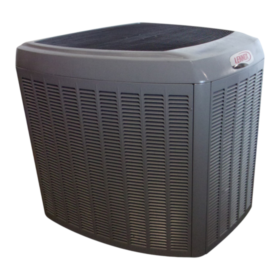
The XP19 is a high efficiency residential split−system heat
pump unit, which features a two−step scroll compressor
and R410A refrigerant. XP19 units are available in 2, 3 , 4
and 5 ton sizes. The series is designed for use with an ex-
pansion valve only (approved for use with R410A) in the in-
door unit. This manual is divided into sections which dis-
cuss the major components, refrigerant system, charging
procedure, maintenance and operation sequence.
Information contained in this manual is intended for use by
qualified service technicians only. All specifications are
subject to change.
CAUTION
Physical contact with metal edges and corners while
applying excessive force or rapid motion can result
in personal injury. Be aware of, and use caution when
working nearby these areas during installation or
while servicing this equipment.
CAUTION
To prevent personal injury, or damage to panels, unit
or structure, be sure to observe the following:
While installing or servicing this unit, carefully stow
all removed panels out of the way, so that the panels
will not cause injury to personnel, nor cause damage
to objects or structures nearby, nor will the panels be
subjected to damage (e.g., being bent or scratched).
While handling or stowing the panels, consider any
weather conditions, especially windy conditions,
that may cause panels to be blown around and bat-
tered.
WARNING
Improper installation, adjustment, alteration, service
or maintenance can cause property damage, person-
al injury or loss of life. Installation and service must
be performed by a qualified installer or service
agency.
. . . . . . . . . . . . . . . . . . . . . . . . . . . . . . . . . . . . . .
Specifications / Electrical Data
. . . . . . . . . . . . . . . . . . . . . . . . . . . . . . . . . .
. . . . . . . . . . . . . . . . . . . . . . . . . . . .
. . . . . . . . . . . . . . . . . . . . . . . . . .
Corp. 0510−L4
Revised 06−2008
XP19 SERIES UNITS
Table of Contents
1
. . . . . . . . . . . . . . . . . .
2
3
3
18
Page 1
DANGER
Shock Hazard
Remove all power at disconnect be-
fore removing access panel.
XP19 units use single-pole contac-
tors. Potential exists for electrical
shock resulting in injury or death.
Line voltage exists at all components
(even when unit is not in operation).
. . . . . . . . . . . . . . . . . . . . . . . . . . . . . . . . . .
. . . . . . . . . . . . . . . . . . . . . . . .
. . . . . . . . . . . . . . . . . . . . . . . . . . . . . . .
VIIBrazing Procedure
. . . . . . . . . . . . . . . . . . . . . . . . . .
VIII Diagrams and Operating Sequence
XP19
20
24
24
24
. . . . . . . . . .
25
© 2005 Lennox Industries Inc.
Advertisement

Related Manuals for Lennox XP19-024


Summary of Contents for Lennox XP19-024
-
Page 1: Table Of Contents
......VIII Diagrams and Operating Sequence ..Page 1 © 2005 Lennox Industries Inc. -
Page 2: General
SPECIFICATIONS General Model No. XP19−024 XP19−036 XP19−048 XP19−060 Data Nominal Tonnage (kW) 2 (7.0) 3 (10.6) 4 (14.1) 5 (17.6) Connections Liquid line (o.d.) − in. (mm) 3/8 (9.5) 3/8 (9.5) 3/8 (9.5) 3/8 (9.5) (sweat) Vapor line (o.d.) − in. (mm) 7/8 (22.2) 7/8 (22.2) 7/8 (22.2) -
Page 3: I Application
All major components (indoor blower and coil) must be When panel is correctly positioned and aligned, insert the matched according to Lennox recommendations for the screws and tighten. compressor to be covered under warranty. Refer to the En- gineering Handbook for approved system matchups. - Page 4 TWO−STAGE MODULATED SCROLL XP19 PARTS ARRANGEMENT slider ring OUTDOOR FAN CONTACTOR LSOM DEFROST CONTROL CAPACITOR solenoid actuator coil FIGURE 4 REVERSING VALVE DRIER COMPRESSOR LOW PRESSURE SCROLL FORM SWITCH HIGH PRESSURE SWITCH FIGURE 3 FIGURE 5 ELECTROSTATIC DISCHARGE (ESD) Precautions and Procedures CROSS−SECTION OF SCROLLS CAUTION DISCHARGE...
- Page 5 The scroll compressor is tolerant to the effects of liquid re- TWO−STAGE OPERATION turn. If liquid enters the scrolls, the orbiting scroll is allowed The two−stage scroll compressor operates like any stan- dard scroll compressor with the exception the two−stage to separate from the stationary scroll.
- Page 6 TWO−STAGE MODULATION Bypass Ports Bypass Ports Closed Open High Capacity Low Capacity FIGURE 8 INTERNAL SOLENOID (L34) Procedure 1−. Turn main power "OFF" to outdoor unit. The internal unloader solenoid controls the two−stage op- 2−. Adjust room thermostat set point above (heating op- eration of the compressor by shifting a slide ring mecha- eration on heat pump) or below (cooling operation) the nism to open (low capacity) or close (high capacity), two...
- Page 7 TABLE 1 Compressor Operation Y1 − Y2 − 1st-Stage Expected Results 2nd-Stage Unit Readings Compressor Voltage Same Amperage Higher Condenser Fan motor Amperage Same or Higher Temperature Ambient Same Outdoor Coil Discharge Air Higher in Cooling Lower in Heating Compressor Discharge Line Higher Indoor Return Air Same...
- Page 8 Bad Solenoid The controller is primarily an a.c. to d.c. converter. Con- verted d.c. power is used to drive the motor. The control- a. Measure the resistance at the 2−pin fusite. The resist- ance should be 32 to 60 ohms depending on compressor ler contains a microprocessor which monitors varying temperature.
- Page 9 Initial Power Up Troubleshooting When line voltage is applied to the motor, there will be a If first or second stage thermostat call for cool is present large inrush of power lasting less than 1/4 second. This in- and the variable speed condenser fan motor does not ener- rush charges a bank of DC filter capacitors inside the con- gize, check voltage at the breaker box.
- Page 10 A compressor oil sample must be taken to determine if excessive moisture has been introduced to the oil. Table 3 lists kits available from Lennox to check POE oils. If oil sample taken from a system that has been exposed to open air does not test in the dry color range, the filter drier MUST be replaced.
- Page 11 Y2 room thermostat connection While the compressor is not running, LSOM will not power the solenoid, re- The Lennox system operation monitor (LSOM) is a 24 volt gardless of the state of Y2. If alert codes 1 or 9 (see...
- Page 12 TABLE 4 System Operation Monitor LED Troubleshooting Codes Status LED Condition Status LED Description Status LED Troubleshooting Information Green Power" LED ON Module has power 24VAC control power is present at the module terminal. Green Power" LED Module not powering up Determine/verify that both R and C module terminals are connected and voltage is present at both terminals.
- Page 13 J−Defrost System during the defrost cycle and 90 seconds after the termina- tion of defrost The demand defrost controller measures differential tem- when the average ambient sensor temperature is below peratures to detect when the system is performing poorly 15° F (−9°C) because of ice build−up on the outdoor coil.
- Page 14 Ambient and Coil Sensor Discharge Sensor 5750 7450 9275 11775 15425 19975 1000 1175 26200 1400 1700 34375 2025 46275 2500 3000 62700 3750 85300 4650 5825 10000 30000 50000 70000 90000 1000 2000 3000 4000 5000 6000 RESISTANCE (OHMS) RESISTANCE (OHMS) FIGURE 16 Sensor Locations...
- Page 15 4−. If the board recognizes five temperature sensor range Operational Description faults during a single (Y1) compressor demand, it re- The defrost control board has three basic operational verts to a lockout mode and displays the appropriate modes: normal, calibration, and defrost. code.
- Page 16 Actuation When the reversing valve is de−energized, the Test Mode When Y1 is energized and 24V power is be- Y1 circuit is energized, and the coil temperature is below ing applied to the board, a test cycle can be initiated by 35°F (2°C), the board logs the compressor run time.
- Page 17 Calibration Mode Sequence Occurs after power up, after cooling operation, or if the coil temperature exceeds the termination temperature while in Heat Mode. DCB defaults to 34 minutes Time/Temperature Mode Reset Compressor Runtime / Reset Three / Five Strike Counter DEMAND MODE 34 MIN.
- Page 18 TABLE 6 Defrost Control Board Diagnostic LEDs Green Condition/Code Possible Cause(s) Solution Power problem No power (24V) to board termi- Check control transformer power (24V). nals R & C or board failure. If power is available to board and LED(s) do not light, replace board.
-
Page 19: Refrigerant System
K−Crankcase Heater (HR1) Field refrigerant piping consists of liquid and vapor lines from the outdoor unit (sweat connections). Use Lennox Compressors in all units are equipped with a 70 watt belly- L15 series line sets as shown in table 7. - Page 20 A−Service Valves The ball valve is equipped with a service port with a factory− installed Schrader valve. A service port cap protects the Access the liquid line and vapor line service valves (figures Schrader valve from contamination and assures a leak− 21 and 22) and gauge ports are used for leak testing, eva- free seal.
-
Page 21: Charging
IV−CHARGING 5 − Connect the manifold gauge set high pressure hose to the vapor valve service port. (Normally, the high pres- Units are factory charged with the amount of R410A refrig- sure hose is connected to the liquid line port; however, erant indicated on the unit rating plate. - Page 22 Attach the manifold center port hose to a nitrogen cylin- Weighing in the Charge TXV Systems – der with pressure regulator set to 150 psig (1034 kPa) Outdoor Temp. < 65_F (18_C) and purge the hose. Open the manifold gauge valves If the system is void of refrigerant, or if the outdoor ambient to break the vacuum in the line set and indoor unit.
- Page 23 TABLE 10 IMPORTANT 2nd stage High Capacity Subcooling Values for Charging Use table 12 and table 13 as a general guide when performing maintenance checks. This is not a proce- Second-Stage (High Capacity) Subcooling Values dure for charging the unit (Refer to Charging/Check- −...
- Page 24 Table 14 R410A Temperature/Pressure Chart Temperature Pressure Temperature Pressure Temperature Pressure Temperature Pressure °F Psig °F Psig °F Psig °F Psig 100.8 178.5 290.8 445.9 102.9 181.6 295.1 451.8 105.0 184.3 299.4 457.6 107.1 187.7 303.8 463.5 109.2 190.9 308.2 469.5 111.4 194.1...
-
Page 25: Service And Recovery
V−SERVICE AND RECOVERY Outdoor Unit 1 − Clean and inspect outdoor coil (may be flushed with a WARNING water hose). Ensure power is off before cleaning. 2 − Outdoor unit fan motor is prelubricated and sealed. No Polyol ester (POE) oils used with R410A refrigerant absorb moisture very quickly. - Page 26 VIII−DIAGRAM / OPERATING SEQUENCE Page 26...
- Page 27 Sequence of Operation XP19−024/060 5 − The compressor will run on low capacity for 5 seconds. The diagnostic module (LSOM) will confirm low stage First Stage Cool (low capacity) operation and then output a 24volt DC signal to the L34 Transformer from indoor unit supplies 24VAC power to internal high capacity solenoid valve in the compres- the thermostat and outdoor unit controls.
Need help?
Do you have a question about the XP19-024 and is the answer not in the manual?
Questions and answers