
Related Manuals for Dahua Technology DH-IPC-HFW3


Summary of Contents for Dahua Technology DH-IPC-HFW3
- Page 1 Bullet Network Camera Quick Start Guide V1.0.1 ZHEJIANG DAHUA VISION TECHNOLOGY CO., LTD.
-
Page 2: Foreword
Quick Start Guide Foreword General This manual introduces the installation and operations of network camera. Read carefully before using the device, and keep the manual safe for future reference. Safety Instructions The following signal words might appear in the manual. Signal Words Meaning Indicates a medium or low potential hazard which, if not avoided,... - Page 3 Quick Start Guide errors in the print. If there is any doubt or dispute, we reserve the right of final explanation. ● Upgrade the reader software or try other mainstream reader software if the manual (in PDF format) cannot be opened. ●...
-
Page 4: Important Safeguards And Warnings
Quick Start Guide Important Safeguards and Warnings This section introduces content covering the proper handling of the device, hazard prevention, and prevention of property damage. Read carefully before using the device, comply with the guidelines when using it. Transportation Requirements ●... - Page 5 Quick Start Guide against lightning. For outdoor scenarios, strictly comply with the lightning protection regulations. ● Ground the function earthing portion of the device to improve its reliability (certain models are not equipped with earthing holes). The device is a class I electrical appliance. Make sure that the power supply of the device is connected to a power socket with protective earthing.
- Page 6 Quick Start Guide replace the desiccant. Desiccants might not be provided depending on the actual model. ● Use the accessories suggested by the manufacturer. Installation and maintenance must be performed by qualified professionals. ● Do not directly touch the photosensitive CMOS. Use an air blower to clean the dust or dirt on the lens.
-
Page 7: Table Of Contents
Quick Start Guide Table of Contents Foreword ........................................I Important Safeguards and Warnings ............................III 1 Introduction ......................................1 1.1 Cable ........................................ 1 1.2 Connecting Alarm Input/Output ............................2 2 Network Configuration ..................................4 2.1 Initializing the Camera ................................4 2.2 Changing the Device IP Address ............................5 2.3 Logging in to the Webpage .............................. -
Page 8: Introduction
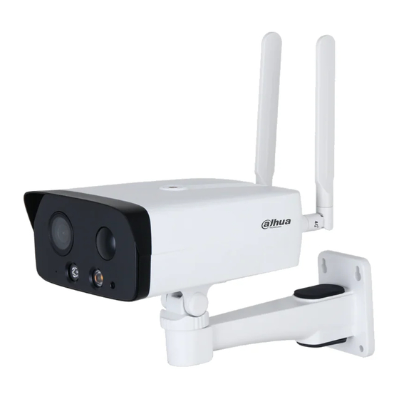
Quick Start Guide 1 Introduction 1.1 Cable Waterproof all the cable joints with insulating tape and waterproof tape to avoid water damage and prevent short circuits from occurring. For details, see the FAQ manual. Figure 1-1 Cables Table 1-1 Cable information Port Name Description Inputs 12 VDC power to charge the battery. -
Page 9: Connecting Alarm Input/Output
Quick Start Guide Table 1-2 Description of Alarm I/O port Port Name Description ALARM_IN Receives the switch signals of external alarm source. Connect different alarm input devices to the same ALARM_IN_GND ALARM_IN_GND port. ALARM_OUT Outputs alarm signals to alarm devices. When connecting to alarm device, only the ALARM_OUT port and ALARM_OUT_GND ALARM_OUT_GND port with the same number can be used... - Page 10 Quick Start Guide switches to low- level when an alarm is triggered (As long as the operating current is below 300 mA, the output low-level voltage is lower than 0.8 V). ● Mode B: switch application. Alarm output is used to drive the external circuit, the maximum voltage is 12 V and the maximum current is 300 mA.
-
Page 11: Network Configuration
Quick Start Guide 2 Network Configuration Device initialization and IP configurations can all be managed with the ConfigTool or through the webpage. For more information, see the web operation manual. ● Device initialization is available on select models, and is required at first-time use and after the device is reset. -
Page 12: Changing The Device Ip Address
Quick Start Guide Step 3 Select Auto-check for updates as needed, and then click OK to initialize the device. If initialization failed, click to see more information. Click Finish. Step 4 2.2 Changing the Device IP Address ● You can change the IP address of one or more devices at a time. This section is based on changing IP addresses in batches. -
Page 13: Operating With Dmss
Quick Start Guide 3 Operating with DMSS Prerequisites Make sure that there are no obstacles and electromagnetic interference between the device and the router for best possible wireless performance. Procedure Step 1 Power on the device. Step 2 Check the status of device indicator light. Table 3-1 Indicator light pattern Indicator Status Device Status... -
Page 14: Installation
Quick Start Guide 4 Installation 4.1 Packing List ● Tools required for installation, such as the electric drill, are not included in the package. ● The operation manual and information on the tools are on the disk or the QR code. Figure 4-1 Packing list 4.2 Dimensions Figure 4-2 Dimensions (mm [inch]) -
Page 15: Installing The Camera
Quick Start Guide 4.3 Installing the Camera 4.3.1 Installation Methods Figure 4-3 Installation methods 4.3.2 Installing the Antennas Figure 4-4 Install the antennas 4.3.3 (Optional) Installing the SD Card ● SD card slot is available on select models. ● Disconnect the power before installing or removing the SD card. Press the reset button for 10 seconds to reset the device. -
Page 16: Attaching The Camera
Quick Start Guide 4.3.4 Attaching the Camera Make sure that the mounting surface is strong enough to hold at least three times the weight of the camera and bracket. Figure 4-6 Cable going through the side cable tray Figure 4-7 Cable going through the mounting surface 4.3.5 (Optional) Installing the Waterproof Connector This section is only necessary if a waterproof connector is included in your package, and the device is... -
Page 17: Adjusting The Lens Angle
Quick Start Guide being installed outdoors. Figure 4-8 Install the waterproof connector 4.3.6 Adjusting the Lens Angle Due to the detection requirement of infrared detector (PIR), we recommend you install the device at the height of 2 m to 3 m from the ground, and the horizontal angle ranges from 10° to 30°. Figure 4-9 Adjust the lens angle... - Page 18 Quick Start Guide...
Need help?
Do you have a question about the DH-IPC-HFW3 and is the answer not in the manual?
Questions and answers