Sign In
Upload
Download
Table of Contents
Contents
Add to my manuals
Delete from my manuals
Share
URL of this page:
HTML Link:
Bookmark this page
Add
Manual will be automatically added to "My Manuals"
Print this page
×
Bookmark added
×
Added to my manuals
Manuals
Brands
Cisco Manuals
Server
3500 Series
Installation manual
Cisco 3500 Series Installation Manual
Hide thumbs
1
2
Table Of Contents
3
4
5
6
7
8
9
10
11
12
13
14
15
16
17
18
19
20
21
22
23
24
25
26
27
28
29
30
31
32
33
34
35
36
page
of
36
Go
/
36
Contents
Table of Contents
Bookmarks
Table of Contents
Table of Contents
Cisco SNS 3500 Series Appliance Overview
Cisco SNS 3500 Series Appliances
LED Indicators on Cisco SNS 3515 and 3595 Appliances
Cisco SNS-3515 and SNS-3595 Appliances Hardware Specifications
Cisco SNS-3515 or 3595 Appliance Front Panel View
Cisco SNS 3515 or SNS 3595 Appliance Back Panel View
Internal Diagnostic Leds
Regulatory Compliance
Before You Begin
Safety Guidelines
Unpack and Inspect the Server
Prepare for Server Installation
Installation Guidelines
Rack Requirements
Equipment Requirements
Slide Rail Adjustment Range
Server Specifications
Physical Specifications
Environmental Specifications
Power Specifications
Install the Cisco SNS 3515 and Cisco SNS 3595 Hardware Appliances
Install the Cisco SNS 3515 or 3595 Appliance in a Rack
Install the Side Rails
Install the Cable Management Arm (Optional)
Reverse the Cable Management Arm (Optional)
Connect Cables
Connect the Network Interface
Connect the Console
Connect the Keyboard and Video Monitor
Cable Management
Connect and Power on the Cisco SNS 3515 or 3595 Appliance
Connect and Power on the Server (Standalone Mode)
Cisco Integrated Management Controller
Setup CIMC Configuration Utility
NIC Modes and NIC Redundancy Settings
Upgrade the BIOS and Cisco IMC Firmware
Access the System BIOS
Advertisement
Quick Links
1
Cisco Sns 3500 Series Appliance Overview
2
Cisco Sns-3515 and Sns-3595 Appliances Hardware Specifications
Download this manual
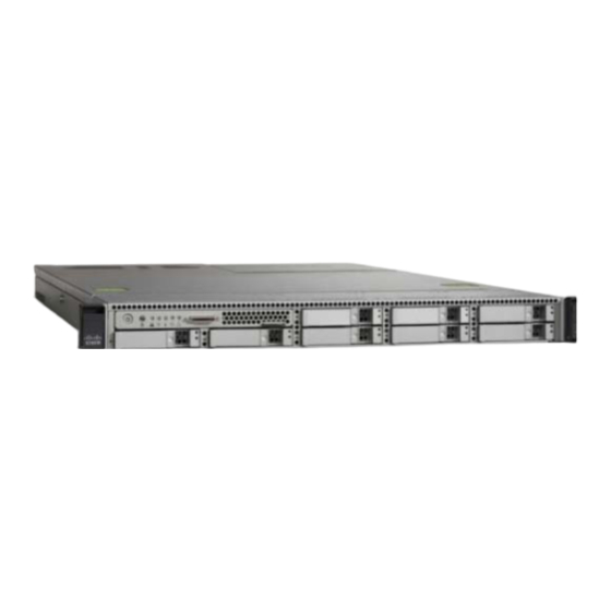
Cisco Secure Network Server 3500 Series Appliance Hardware
Installation Guide
First Published: 2016-10-10
Americas Headquarters
Cisco Systems, Inc.
170 West Tasman Drive
San Jose, CA 95134-1706
USA
http://www.cisco.com
Tel: 408 526-4000
800 553-NETS (6387)
Fax: 408 527-0883
Table of
Contents
Previous
Page
Next
Page
1
2
3
4
5
Advertisement
Table of Contents
Need help?
Do you have a question about the 3500 Series and is the answer not in the manual?
Ask a question
Questions and answers
Subscribe to Our Youtube Channel
Related Manuals for Cisco 3500 Series
Server Cisco SNS 3400 Series Software Installation
(38 pages)
Server Cisco IE-3000-8TC Administration Manual
Administration guide (496 pages)
Server Cisco Cisco Access Registrar 3.5 Reference Manual
Cisco systems server concepts and reference guide (80 pages)
Server Cisco Firepower Management Center 750 Getting Started Manual
Firepower management center (42 pages)
Server Cisco UCS C240 M5 Installation And Service Manual
(169 pages)
Server Cisco UCS C220 M4 Installation And Service Manual
(134 pages)
Server Cisco UCS C240 Installation And Service Manual
(156 pages)
Server Cisco UCS C24 Installation And Service Manual
(156 pages)
Server Cisco APIC M3 Installation And Service Manual
(130 pages)
Server Cisco UCS C Series Configuration Manual
Integrated management controller gui (88 pages)
Server Cisco ONS 15454 Hardware Installation Manual
(516 pages)
Server Cisco CDE 220 Series Hardware Installation Manual
Content delivery engine (248 pages)
Server Cisco UCS X210c M6 Installation And Service Note
Compute node (86 pages)
Server Cisco Firepower 2100 Series Hardware Installation Manual
(84 pages)
Server Cisco CSACS-1121-K9 Reference Manual
Reference guide (190 pages)
Server Cisco MSE 3365 Installation Manual
(10 pages)
This manual is also suitable for:
Sns 3515
Sns 3595
Sns-3515-k9
Sns-3595-k9
Table of Contents
Print
Rename the bookmark
Delete bookmark?
Delete from my manuals?
Login
Sign In
OR
Sign in with Facebook
Sign in with Google
Upload manual
Upload from disk
Upload from URL


Need help?
Do you have a question about the 3500 Series and is the answer not in the manual?
Questions and answers