Table of Contents
Advertisement
Quick Links
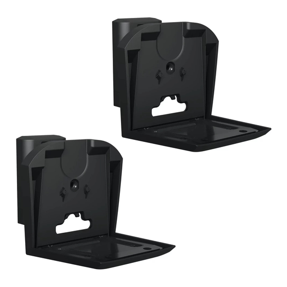
WSWM E31 and WSWM E32
Tilt & Swivel Speaker Wall Mount
For SONOS
Era 300
®
INSTRUCTION MANUAL
US: +1 (800) 359-5520 • EMEA: +31 (0) 495 580 852 • UK: +44 (0) 800 056 2853
Texto en español, página 20
Texte français page 22
™
We'll Make It Stress-Free
If you have any questions along the way, just give us a call.
We're ready to help!
Deutscher Text Seiten 24
Nederlandse tekst op pagina 26
Svensk text sida 28
Русский текст: стр. 30
中文文字说明请参见第 32 页
日本語は 34 ページ
Advertisement
Table of Contents

Related Manuals for LEGRAND SANUS WSWME11-W2


Summary of Contents for LEGRAND SANUS WSWME11-W2
- Page 1 WSWM E31 and WSWM E32 Tilt & Swivel Speaker Wall Mount For SONOS Era 300 ® ™ INSTRUCTION MANUAL We’ll Make It Stress-Free If you have any questions along the way, just give us a call. US: +1 (800) 359-5520 • EMEA: +31 (0) 495 580 852 • UK: +44 (0) 800 056 2853 We’re ready to help! Texto en español, página 20 Deutscher Text Seiten 24...
-
Page 2: Tools Needed
IMPORTANT SAFETY INSTRUCTIONS — PLEASE READ ENTIRE MANUAL PRIOR TO USE — SAVE THESE INSTRUCTIONS Before getting started, let’s make sure this product is perfect for you! This mount is designed to support only Sonos® Era 300™ speakers. CAUTION: Avoid potential personal injuries and property damage! •... - Page 3 Dimensions 0.22in 2.32in 5.6mm 59mm 3.50in 1.17in 0.84in 88.9mm 29.8mm 21.3mm 3.00in 6.89in 76.1mm 175.1mm 1.73in 44mm 1.97in 0.26in 50mm 6.6mm 4 deg UP TILT 4.82in 4.04in 122.4mm 102.6mm 32 deg 4.91in DOWN TILT 124.8mm 32deg 32deg...
- Page 4 Supplied Parts and Hardware WARNING: This product contains small items that could be a choking hazard if swallowed. Before starting assembly, verify all parts are included and undamaged. If any parts are missing or damaged, do not return the damaged item to your dealer; contact Customer Service.
- Page 5 STEP 2 STEP 3 Wall Plate Screw Speaker Screw STEP 4 Wall Plate Drywall / Concrete Anchor Wall Cap...
-
Page 6: Installation
STEP 1 Assemble Brackets BELOW Eye Level Installation... - Page 7 ABOVE Eye Level Installation (Speaker Upside Down)
- Page 8 STEP 2 Attach Speaker to Bracket...
-
Page 10: Attach Wall Plate To Wall
STEP 3-A Attach Wall Plate to Wall Drywall Only Installation CAUTION: Avoid potential personal injury or property damage! ● Drywall covering the wall, must not be less than 1/2 in. (12.7 mm) 1 in. (2.5 cm) Min. 1/2 in. (12.7 mm) 3/8 in. - Page 11 CAUTION: Avoid potential personal injury or property damage! DO NOT use power tools for this step. MUST BE firmly tightened to prevent unwanted movement of the wall plate . Ensure the wall plate is securely fastened to the wall before continuing Both screws on to the next step, but DO NOT overtighten the screws.
-
Page 12: Wood Stud Installation
STEP 3-B Attach Wall Plate to Wall Wood Stud Installation CAUTION: Avoid potential personal injury or property damage! ● Drywall covering the wall, must not exceed 5/8 in. (16 mm) ● Minimum wood stud size: nominal 2 x 4 in. (51 x 102 mm) actual 1½ x 3½ in. (38 x 89 mm) ●... - Page 13 CAUTION: Avoid potential personal injury or property damage! DO NOT use power tools for this step. MUST BE firmly tightened to prevent unwanted movement of the wall plate . Ensure the wall plate is securely fastened to the wall before continuing Both screws on to the next step, but DO NOT overtighten the screws.
- Page 14 Attach Wall Plate to Wall Solid Concrete or Concrete Block Installation STEP 3-C CAUTION: Avoid potential personal injury or property damage! ● Mount the wall plate directly onto the concrete surface (no wall covering) ● Minimum solid concrete thickness: 8 in. (203 mm) ●...
- Page 15 CAUTION: Avoid potential personal injury or property damage! DO NOT use power tools for this step. MUST BE firmly tightened to prevent unwanted movement of the wall plate . Ensure the wall plate is securely fastened to the wall before continuing Both screws on to the next step, but DO NOT overtighten the screws.
- Page 16 STEP 4 Mount Assembly to Wall Plate...
-
Page 18: Side To Side
Adjustments TILT DOWN SIDE TO SIDE TILT UP... - Page 19 To Remove...
- Page 20 EMEA: +31 (0) 495 580 852 Legrand AV Inc. and its affiliated corporations and subsidiaries (collectively, “Legrand”), intend to make this manual accurate and complete. However, Legrand AV makes no claim that the information contained herein covers all details, conditions, or variations. Nor does it provide for every possible contingency in connection with the installation or use of this product. The information contained in this document is subject to change without notice or obligation of any kind.
Need help?
Do you have a question about the SANUS WSWME11-W2 and is the answer not in the manual?
Questions and answers