Table of Contents
Advertisement
Quick Links
Advertisement
Table of Contents

Subscribe to Our Youtube Channel
Related Manuals for Supero Supero C2G41


Summary of Contents for Supero Supero C2G41
- Page 1 C2G41 USER’S MANUAL Revision 1.0...
- Page 2 Please Note: For the most up-to-date version of this manual, please see our web site at www.supermicro.com. Super Micro Computer, Inc. ("Supermicro") reserves the right to make changes to the product described in this manual at any time and without notice. This product, including software, if any, and documentation may not, in whole or in part, be copied, photocopied, reproduced, translated or reduced to any medium or machine without prior written consent.
-
Page 3: Manual Organization
About This Manual This manual is written for system integrators, PC technicians and knowledgeable PC users. It provides information for the installation and use of the Supermicro C2G41 motherboard. The C2G41 motherboard supports a single Intel® Core 2 Quad/Duo, Pentium® and Celeron® processor with a system bus speed of 1333/1066/800 MHz. -
Page 4: Table Of Contents
Manual Organization ....................iii Conventions Used in the Manual .................. iii Chapter 1: Introduction Overview ......................1-1 Checklist ..................... 1-1 Contacting Supermicro ................1-2 C2G41 Image ................1-3 C2G41 Layout ................1-4 C2G41 Quick Reference ............. 1-5 Motherboard Features ................1-6 Intel G41 Chipset: System Block Diagram .......... - Page 5 Table of Contents Chassis Intrusion ..................2-23 Fan Headers ..................... 2-24 Overheat/Fan Fail LED (JOH) ..............2-23 ATX PS/2 Keyboard and PS/2 Mouse Ports ..........2-25 Serial Ports ....................2-25 Wake-On-Ring ..................2-25 Wake-On-LAN ..................2-26 GLAN1 Port ....................2-27 Speaker Connector ..................
- Page 6 C2G41 User’s Manual Security Settings .................... 4-19 Boot Configuration ..................4-20 Exit Options ....................4-21 Appendices: Appendix A: BIOS POST Messages .................A-1 Appendix B: Installing the Microsoft® Windows® OS ..........B-1 Appendix C: Software Driver Installation Instructions ..........C-1 Appendix D: BIOS Recovery ..................D-1...
-
Page 7: Chapter 1: Introduction
Checklist Congratulations on purchasing your computer motherboard from an acknowledged leader in the industry. Supermicro boards are designed with the utmost attention to detail to provide you with the highest standards in quality and performance. Please check that the following items have all been included with your mother- board. -
Page 8: Contacting Supermicro
Super Micro Computer, Inc. 980 Rock Ave. San Jose, CA 95131 U.S.A. Tel: +1 (408) 503-8000 Fax: +1 (408) 503-8008 Email: marketing@supermicro.com (General Information) support@supermicro.com (Technical Support) Web Site: www.supermicro.com Europe Address: Super Micro Computer B.V. Het Sterrenbeeld 28, 5215 ML... -
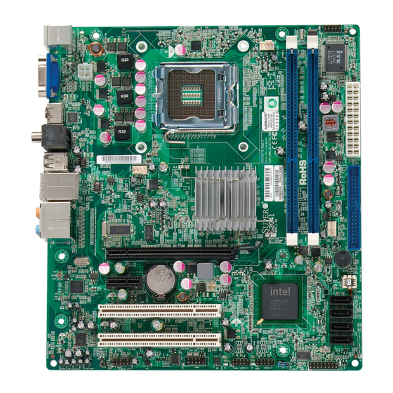
Page 9: C2G41 Image
Chapter 1: Introduction C2G41 Image Note: All pictures and drawings shown in this manual were based upon the latest PCB Revision available at the time of publishing of the manual. The motherboard you've received may or may not look exactly the same as those in this manual. -
Page 10: Motherboard Layout
C2G41 User’s Manual Motherboard Layout KB/MOUSE PSKBM SLOT7 PCI-E X16 SLOT6 PCI-E X1 JWOL I-SATA3 I-SATA2 SLOT5 PCI 33MHZ I-SATA1 SLOT4 PCI 33MHZ I-SATA0 COM2 USB0/1 USB2/3 AUDIO FP JPT1 JPT1 ENABLE DISABLE Important Notes to the User • Jumpers not indicated are for test purposes only. •... -
Page 11: C2G41 Quick Reference
Chapter 1: Introduction C2G41 Quick Reference Jumpers Description Default Setting JBT1 CMOS Clear (See Chapter 2) JPT1 Trusted Platform Module Enable Pins 1-2 (Enabled) Connectors Description JPW1 ATX 24-Pin Power Connector COM1, COM2 COM1 and COM2 Header Connectors Memory Slots DIMM 1A, 1B FAN 1-3 Fan 1: CPU Fan, Fan 2/3: Chassis Fan Headers... -
Page 12: Motherboard Features
C2G41 User’s Manual Motherboard Features Supported Processors • Single Intel Core 2 Duo/Core 2 Quad/Pentium®/Celeron Processor with a system bus speed of 1333/1066/800 MHz. • Supports Intel Dual Core Technology, Thermal Management 2 (TM2). Memory • Supports single or dual channel unbuffered non-ECC DDR3 memory, up to 4GB at 1066/800 MHz for single channel mode or dual-channel interleaved mode in four DIMM sockets. - Page 13 Chapter 1: Introduction Onboard I/O Disc Drive • Four (4) SATA ports • One (1) EIDE Controller (supports 2 IDE devices) Video and Graphics • One (1) Onboard VGA Connector (Intel GMA X4500) • One (1) HDMI 1.3 port Audio •...
-
Page 14: Block Diagram
C2G41 User’s Manual Block Diagram INTEL LGA 775 pin VRM 11.1 Intel P4 Processor Core 2 Duo & Core 2 Quad & Dual Core FSB : 1333/1066/800MHz HDMI MUX & HDMI BW : 10GB/s Level shifter DDR3 :1066/800MHz INTEL DIMM1A: DDR3 Socket 240P GMCH PCIE x16 BW : 8G/s @Freq : 100MHz... -
Page 15: Chipset Overview
Chapter 1: Introduction Chipset Overview The Intel® G41 Express Chipset, combined wtih the Intel Core 2 processor fam- ily and the ICH7 I/O controller offers an uncomparable match to deliver new digital capabilities for the home consumer. Also included with the C2G41 motherboard is the Intel Graphics Media Accelerator (Intel GMA X4500) for built-in support for smooth high-definition video playback without the need for third-party accelerators or decoders. -
Page 16: Recovery From Ac Power Loss
C2G41 User’s Manual Recovery from AC Power Loss BIOS provides a setting for you to determine how the system will respond when AC power is lost and then restored to the system. You can choose for the system to remain powered off (in which case you must hit the power switch to turn it back on) or for it to automatically return to a power on state. -
Page 17: Power Supply
Chapter 1: Introduction hance clock control. A hardware-based component provides software-independent thermal management that is compatible with the ACPI Revision 3.0a. Slow Blinking LED for Suspend-State Indicator When the CPU goes into a suspend state, the chassis power LED will start blinking to indicate that the CPU is in suspend mode. -
Page 18: Super I/O
C2G41 User’s Manual High Definition Video (HDMI) The C2G41 also includes a High-Definition Multimedia Interface (HDMI) connector on the motherboard. This connector transmits digital video signals, providing superb multimedia interface support. With these versatile audio and video capabilities built in, this motherboard provides the user with a state of the art audio/video experience that is larger than life. -
Page 19: Chapter 2: Installation
Chapter 2: Installation Chapter 2 Installation Electro-Static Sensitive Devices Electro-static Discharge (ESD) can damage electronic com ponents. To prevent dam- age to your system board, it is important to handle it very carefully. The following measures are generally sufficient to protect your equipment from ESD. Precautions •... -
Page 20: Motherboard Installation
C2G41 User's Manual Motherboard Installation All motherboards have standard mounting holes to fit different types of chassis. Make sure that the locations of all the mounting holes for both motherboard and chassis match. Although a chassis may have both plastic and metal mounting fas- teners, metal ones are highly recommended because they ground the motherboard to the chassis. -
Page 21: Installation Instructions
Chapter 2: Installation Installation Instructions Install the I/O shield into the chassis. I/O Shield Locate the mounting holes on the motherboard. Refer to the layout on the previous page for mounting hole locations. Locate the matching mounting holes on the chassis. Install standoffs in the chassis as needed. -
Page 22: Processor And Heatsink Installation
C2G41 User's Manual Processor and Heatsink Installation Warning: When handling the processor package, avoid placing direct pressure on the label area of the fan. Notes: 1. Always connect the power cord last and always remove it before add- ing, removing or changing any hardware components. Make sure that you install the processor into the CPU LGA 775 socket before you install the CPU heatsink. - Page 23 Chapter 2: Installation Gently lift the load lever to open the load plate. Use your thumb and your index finger to hold the CPU at the top center edge and the bottom center edge of the CPU. North Center South Center Edge Align CPU Pin1 (the CPU corner marked with a triangle) against the socket corner that is marked with a triangle cutout.
- Page 24 C2G41 User's Manual Do not rub the CPU against the surface or against any pins of the socket to avoid damage to the CPU or the socket.) With the CPU inside the socket, inspect the four corners of the CPU to make sure that the CPU is properly installed.
- Page 25 Chapter 2: Installation If the CPU is properly installed into the socket, the plastic PnP cap will be automatically released from the load plate when the load lever is pushed in the lever lock. Remove the PnP cap from the motherboard. Load lever locked into place CPU properly...
-
Page 26: Installing An Active Fan Cpu Heatsink
C2G41 User's Manual Installing an Active Fan CPU Heatsink Note: Heatsink and hardware are not supplied with the motherboard. Locate the CPU Fan power connector on the motherboard. (Refer to the layout on the right for the CPU Fan location.) Position the heatsink so that the heatsink fan wires are closest to the CPU fan power connector... - Page 27 Chapter 2: Installation Align the four heatsink fasteners with the mounting holes on the moth- erboard. Gently push the pairs of diagonal fasteners (#1 & #2, and #3 & #4) into the mounting holes until you hear a click. (Note: Make sure to orient each fastener so that the narrow end of the groove is pointing outward.) Repeat Step 7 to insert all four heat-...
-
Page 28: Removing The Heatsink
C2G41 User's Manual Removing the Heatsink Warning: We do not recommend that the CPU or the heatsink be re- moved. However, if you do need to remove the heatsink, please follow the instructions below to uninstall the heatsink and prevent damage to the CPU or other components. -
Page 29: Installing A Passive Cpu Heatsink
Chapter 2: Installation Installing a Passive CPU Heatsink Do not apply any thermal grease to the heatsink or the CPU die -- the required amount has already been applied. Place the heatsink on top of the CPU so that the four mounting holes are aligned with those on the Motherboard's and the Heatsink Bracket under- neath. - Page 30 C2G41 User's Manual Removing the Heatsink Warning: We do not recommend that the CPU or the heatsink be removed. However, if you do need to uninstall the heatsink, please follow the instruc- tions below to uninstall the heatsink to prevent damage done to the CPU or the CPU socket.
-
Page 31: Installing Ddr3 Memory
Chapter 2: Installation Installing DDR3 Memory Note: Check the Supermicro web site for recommended memory modules. CAUTION Exercise extreme care when installing or removing DIMM modules to prevent any possible damage. DIMM Installation Insert the desired number of DIMMs into the memory slots, starting with DIMM1A. - Page 32 C2G41 User's Manual The DDR3 Slot Position the DIMM module's bottom key so it aligns with the receptive point on the slot. Notches Release Push the Lock/Release tabs to their Release positions. Make sure that the DIMM module's side Release notches align with the slot's Lock/Release tabs as it is Lock/Release Tabs...
- Page 33 Chapter 2: Installation Note: Due to memory allocation to system devices, the amount of memory that remains available for operational use will be reduced when 4 GB of RAM is used. The reduction in memory availability is disproportional. For Microsoft Windows users: Microsoft implemented a design change in Win- dows XP with Service Pack 2 (SP2) and Windows Vista.
-
Page 34: Control Panel Connectors/Io Ports
C2G41 User's Manual Control Panel Connectors/IO Ports The I/O ports are color coded in conformance with the PC 99 specification. See Figure below for the colors and locations of the various I/O ports. 1. Back Panel Connectors/IO Ports KB/MOUSE PSKBM SLOT7 PCI-E X16 SLOT6 PCI-E X1 JWOL... -
Page 35: Back Panel Connectors - Descriptions
Chapter 2: Installation Back Panel Connectors - Descriptions Keyboard (Purple) - this port is for a keyboard with a PS/2-type con- nector. PS/2 Mouse (Green) - attach a PS/2-type pointing device to this con- nector, such as a mouse or a trackball. VGA - this is the default VGA display connector. HDMI - for High Definition monitors with an HDMI interface. -
Page 36: Front Control Panel
C2G41 User's Manual 2. Front Control Panel JF1 contains header pins for various buttons and indicators that are normally located on a control panel at the front of the chassis. These connectors are de- signed specifically for use with Super Micro server chassis. See Figure below for the descriptions of the various control panel buttons and LED indicators. -
Page 37: 3. Front Control Panel Pin Definitions
Chapter 2: Installation 3. Front Control Panel Pin Definitions Power LED Power LED Pin Definitions (JF1) The Power LED connection is located Pin# Definition on pins 15 and 16 of JF1. Refer to the LED_Anode+ table on the right for pin definitions. PWR LED Signal HDD LED The HDD LED connection is located on pins 13 and 14 of JF1. -
Page 38: Oh/Fan Fail Led
C2G41 User's Manual NIC1 Indicator GLAN 1 LED Pin Definitions (JF1) The NIC (Network Interface Control- Pin# Definition ler) LED connection for the GLAN port LED_Anode+ is located on pins 11 and 12 of JF1. NIC1 LED Attach the NIC LED cables to display Signal network activity. -
Page 39: Reset Button
Chapter 2: Installation Reset Button Reset Button Pin Definitions (JF1) The Reset Button connection is located Pin# Definition on pins 3 and 4 of JF1. Attach it to a Reset hardware reset switch on the computer Ground case. Refer to the table on the right for pin definitions. -
Page 40: Connecting Cables
C2G41 User's Manual Connecting Cables ATX/Auxiliary Power ATX Power 24-pin Connector Connectors Pin Definitions Pin# Definition Pin # Definition A 24-pin main power connector is lo- +3.3V +3.3V cated at JPW1. This power connector -12V +3.3V meets the SSI EPS 12V specifica- tion. -
Page 41: Universal Serial Bus (Usb)
Chapter 2: Installation Universal Serial Bus (USB) Front Panel USB (6/7/8/9) and Front-Ac- cessible Onboard USB (10) Connections There are 8 USB 2.0 (Universal Serial Bus) ports/headers on the mother- Pin # Definition Pin # Definition board. Four of them are Back Panel USB ports: USB 4/5 and USB 6/7. The other four are headers that can be used for front panel connections: Ground Ground... -
Page 42: Fan Headers
C2G41 User's Manual Fan Headers Fan Header Pin Definitions (Fan1-3) The C2G41 has three chassis fan headers Pin# Definition (Fan 1 to Fan 3). Fan 1 is the CPU Fan. Fan Ground 2 to Fan 3 are system/chassis fans. +12V Tachometer Note: Pins 1-3 of a 4-pin fan headers PWR Modulation are backward compatible with the tradi- tional 3-pin fans.) See the table on the... -
Page 43: Atx Ps/2 Keyboard And Ps/2 Mouse Ports
Chapter 2: Installation ATX PS/2 Keyboard and PS/2 PS/2 Keyboard and Mouse Ports Mouse Port Pin Definitions The ATX PS/2 keyboard and the PS/2 Pin# Definition mouse are located at J8. See the table Data on the right for pin definitions. (The mouse port is above the keyboard Ground port. -
Page 44: Wake-On-Ring
C2G41 User's Manual Wake-On-LAN Wake-On-LAN Pin Definitions The Wake-On-LAN header is located (JWOL) at JWOL on the motherboard. See the Pin# Definition table on the right for pin definitions. +5V Standby (You must also have a LAN card with Ground a Wake-On-LAN connector and cable Wake-up to use this feature.) A. - Page 45 Chapter 2: Installation GLAN 1 (Gigabit Ethernet Port) A Gigabit Ethernet port is located on the IO backplane. This port accepts RJ45 type cables. GLAN1 Speaker A Speaker/Buzzer is located on the mother- board next to the IDE connector. A. GLAN1 B. Speaker/Buzzer KB/MOUSE PSKBM SLOT7 PCI-E X16...
-
Page 46: High Definition Audio (Hda)
C2G41 User's Manual High Definition Audio (HDA) The C2G41 features a 7.1+2 Channel High Orange: Blue: Line-In CEN/LFE Definition Audio (HDA) codec that provides 10 DAC channels, simultaneously supporting Black: Back Green:Front Surround 7.1 sound playback and two channels of independent stereo sound output (multiple Grey: Side Pink: Mic-In Surround... -
Page 47: Front Panel Audio Control
Chapter 2: Installation Front Panel Audio Control High Definition Fron Panel Audio When front panel headphones are plugged Pin# Signal in, the back panel audio output is disabled. MC_L This is done through the FP Audio header AUD_GND (AUDIO FP). If the front panel interface MC_R card is not connected to the front panel FP_Audio-Detect... -
Page 48: Vga Connector
C2G41 User's Manual VGA Connector A VGA connector is located next to the USB ports on the IO backplane. Refer to the board layout below for the location. HDMI Port The HDMI (High-Definition Multimedia Interface) Port is located next to the USB ports on the I/O backplane, and just below the VGA Connector. -
Page 49: Jumper Settings
Chapter 2: Installation Jumper Settings Explanation of Jumpers To modify the operation of the motherboard, jumpers can be used to choose between optional settings. Jumpers create shorts between two pins to change the function of the connector. Pin 1 is identified with a square solder pad on the printed circuit board. -
Page 50: Tpm Support Enable
C2G41 User's Manual TPM Support Enable TPM Support Enable Jumper Settings JPT1 allows the user to enable TPM Jumper Setting Definition (Trusted Platform Module) support to Enabled enhance data integrity and system Disabled security. See the table on the right for jumper settings. -
Page 51: Onboard Indicators
Chapter 2: Installation Onboard Indicators GLAN Activity Indicator GLAN LEDs Color Status Definition There is one Gigabit-LAN port. This Giga- Yellow Flashing Active bit Ethernet LAN port has two LEDs. The GLAN Link Indicator yellow LED indicates activity, while the Link LED may be green, amber or off to LED Color Definition... -
Page 52: Onboard Power Led
C2G41 User's Manual Onboard Power LED (LE1) Onboard PWR LED Indicator (LE1) The Onboard 3.3V Standby Power LED is located at LE1 on the motherboard. When LED Color Definition LE1 is off, the system is off. When the System Off green light is on, the system is on. When Standby Power On the LED is on, the power is on. -
Page 53: Ide Disk Drive Connector
Chapter 2: Installation Disk Drive Connections Note the following when connecting the hard disk drive cables: • A red mark on a wire typically designates the location of pin 1. IDE Drive Connectors IDE Disk Drive Connector Pin Definitions Pin# Definition Pin # Definition There is one IDE Disk Drive Connector... -
Page 54: Sata Disk Drive Connectors
C2G41 User's Manual SATA Disk Drive Connectors SATA Connectors Pin Definitions Four Serial ATA (SATA) disk drive con- Pin# Signal nectors (I-SATA 0~3) are located on the Ground motherboard to provide serial link con- SATA_TXP nections. Serial Link connections provide SATA_TXN faster data transmission than those of the Ground traditional Parallel ATA. -
Page 55: Chapter 3: Troubleshooting
Chapter 3: Troubleshooting Chapter 3 Troubleshooting Troubleshooting Procedures Use the following procedures to troubleshoot your system. If you have followed all of the procedures below and still need assistance, refer to the ‘Technical Support Procedures’ and/or ‘Returning Merchandise for Service’ section(s) in this chapter. Always disconnect the AC power cord before adding, changing or installing any hardware components. -
Page 56: Memory Errors
1. Please go through the ‘Troubleshooting Procedures’ and 'Frequently Asked Question' (FAQ) sections in this chapter or see the FAQs on our web site (http:// www.supermicro.com/support/faqs/) before contacting Technical Support. 2. BIOS upgrades can be downloaded from our web site at (http://www.supermicro com/support/bios/). -
Page 57: Frequently Asked Questions
4. Distributors: For immediate assistance, please have your account number ready when placing a call to our technical support department. We can be reached by e-mail at support@supermicro.com, by phone at:(408) 503-8000, option 2, or by fax at (408)503-8019. Frequently Asked Questions... - Page 58 Note: The SPI BIOS chip installed on this motherboard is not removable. To repair or replace a damaged BIOS chip, please send your motherboard to RMA at Supermicro for service. Question: I think my BIOS is corrupted. How can I recover my BIOS? Answer: Please see Appendix D, BIOS Recovery for detailed instructions.
-
Page 59: Returning Merchandise For Service
Chapter 3: Troubleshooting Answer: Go to <Start>, <Programs>, <Accessories>, <Entertainment> and then <Volume Control>. Under the Properties tab, scroll down the list of devices in the menu and check the box beside "Microphone". Question: How do I connect the ATA100/66 cable to my IDE device(s)? Answer: The 80-wire/40-pin high-density ATA100/66 IDE cable (not supplied with the motherboard) has two connectors to support two drives. - Page 60 C2G41 User's Manual Notes...
-
Page 61: Chapter 4: Bios
When an option is selected in the left frame, it is highlighted in white. Often a text message will accompany it. (Note: the AMI BIOS has default text messages built in. Supermicro retains the option to include, omit, or change any of these text messages.) The AMI BIOS Setup Utility uses a key-based navigation system called hot keys. -
Page 62: Main Setup
Use [ENTER], [TAB] or [SHIFT-TAB] to System Time [09:20:40] select a field. System Date [Tue 06/14/2009] Use [+] or [-] to Supermicro C2G41 configure system time. Version : 1.00 Build Date : 06/09/09 : 10607000 Processor Intel(R) Core(TM) 2 Duo CPU E8400 @ 3.00GHz... - Page 63 Chapter 4: AMI BIOS DAY/MM/DD/YY format. The time is entered in HH:MM:SS format.(Note: The time is in 24-hour format. For example, 5:30 A.M. appears as 05:30:00.) Supermicro C2G41 This feature displays the version numbers and ID of the motherboard. Version...
-
Page 64: 4-3 Advanced Setup Configuration
C2G41 User’s Manual 4-3 Advanced Setup Configuration Use the arrow keys to select Boot Setup and hit <Enter> to access the submenu items: BIOS SETUP UTILTY Main Advanced Security Boot Exit Advanced Settings Configure Settings during System Boot. Boot Feature Processor & Clock Options ... - Page 65 Chapter 4: AMI BIOS ACPI Configuration Use this feature to configure ACPI (Advanced Configuration and Power Interface) power management settings for your system. ACPI Aware OS Select Yes to enable ACPI support for the OS. Disable this feature if ACPI is not supported by your OS.
- Page 66 C2G41 User’s Manual MPS Revision This feature allows the user to specify the version of the Multi-Processor Specifica- tion (MPS) the motherboard is using. The options are 1.4 and 1.1. Interrupt 19 Capture Interrupt 19 is the software interrupt that handles the boot disk function. When this item is set to Enabled, the ROM BIOS of the host adaptors will "capture"...
- Page 67 Chapter 4: AMI BIOS and Disabled. Note: If there is any change to this setting, you will need to power off and restart the system for the change to take effect. Please refer to Intel’s web site for detailed information. Execute Disable Bit (Available when supported by the OS and the CPU) Set to Enabled to enable the Execute Disable Bit to allow the processor to classify areas in the system memory where an application code can execute and where...
-
Page 68: Advanced Chipset Settings
C2G41 User’s Manual Advanced Chipset Settings The items included in the Advanced Settings submenu are listed below: NorthBridge Configuration This feature allows the user to configure the settings for the Intel 945GME NorthBridge chipset. Memory Remap Feature PCI memory resources will overlap with the total physical memory if 4GB of memory or above is installed on the motherboard. - Page 69 Chapter 4: AMI BIOS PEG - PCI-E Graphics adapter (optional add-on card) PCI - PCI graphics adapter (optional add-on card) IGD - Internal Graphics Display (built-in) IGD Graphics Mode Select Use the feature to set the amount of system memory to be used by the Internal Graphics Devices.
- Page 70 C2G41 User’s Manual Active State Power Management Select Enabled to enable Active-State Power Management for signal transactions between L0 and L1 Links on the PCI Express Bus in order to maximize power- saving and transaction speeds. The options are Enabled and Disabled. USB Functions This feature allows the user to decide the number of onboard USB ports to be enabled.
- Page 71 Chapter 4: AMI BIOS IDE Configuration When this submenu is selected, the AMI BIOS automatically detects the presence of the IDE Devices and displays the following items: ATA/IDE Configuration This feature allows the user to configure the ATA/IDE settings. The options are Disabled, Compatible and Enhanced.
- Page 72 C2G41 User’s Manual Block (Multi-Sector Transfer) Block Mode boosts the IDE drive performance by increasing the amount of data transferred. Only 512 bytes of data can be transferred per interrupt if Block Mode is not used. Block Mode allows transfers of up to 64 KB per interrupt. Select Disabled to allow data to be transferred from and to the device one sector at a time.
- Page 73 Chapter 4: AMI BIOS to use Ultra DMA mode 4 . It has a data transfer rate of 100 MBs. The options are Auto, SingleWordDMAn, MultiWordDMAn, and UltraDMAn. S.M.A.R.T. Self-Monitoring Analysis and Reporting Technology (SMART) can help predict impending drive failures. Select Auto to allow the AMI BIOS to automatically de- tect hard disk drive support.
-
Page 74: Hardware Health Configuration
C2G41 User’s Manual PCI IDE BusMaster Select Enabled to allow the BIOS to use the PCI busmaster to read from and write to the onboard IDE drives. The options are Disabled and Enabled. Slot 4 PCI 33MHz, Slot 5 PCI 33MHz, Slot 6 PCIE X1, Slot 7 PCIE X16 Select Enabled to activate the OPROM for a PCI slot specified. - Page 75 Chapter 4: AMI BIOS instability. When the CPU temperature reaches this predefined threshold, the CPU and system cooling fans will run at full speed. The options are: The Early Alarm: Select this setting if you want the CPU overheat alarm (including the LED and the buzzer) to be triggered as soon as the CPU temperature reaches the CPU overheat threshold as predefined by the CPU manufacturer.
- Page 76 Tolerances’, the installed CPU can now send its ‘Temperature Toler- ance’ to the motherboard resulting in better CPU thermal management. Supermicro has leveraged this feature by assigning a temperature status to certain thermal conditions in the processor (Low, Medium and High). This makes it easier for the user to understand the CPU’s temperature status,...
- Page 77 Chapter 4: AMI BIOS Voltage Monitoring Vcore / Vnbcore / VDIMM / 5V / 12V / 3.3Vcc / Vbat Note: In the Windows OS environment, the Supero Doctor III settings take precedence over the BIOS settings. When first installed, Supero Doctor III adopts the temperature threshold settings previously set in the BIOS.
-
Page 78: Trusted Computing
C2G41 User’s Manual VT-UTF8 Combo Key Support A terminal keyboard definition that provides a way to send commands from a remote console. Available options are Enabled and Disabled. Sredir Memory Display Delay This feature defines the length of time in seconds to display memory information. The options are No Delay, Delay 1 Sec, Delay 2 Sec, and Delay 4 Sec. -
Page 79: Security Settings
Chapter 4: AMI BIOS Security Settings The AMI BIOS provides a Supervisor and a User password. If you use both pass- words, the Supervisor password must be set first. BIOS SETUP UTILTY Main Advanced Security Boot Exit Security Settings Install or Change the password. -
Page 80: 4-5 Boot Configuration
C2G41 User’s Manual Clear User Password (Available only if User Password has been set) Use this option to clear the User Password. The options are OK and Cancel. Password Check Use this option to configure when users are prompted for a password. Available options are Setup and Always. -
Page 81: Exit Options
Chapter 4: AMI BIOS The settings are 1st Floppy Drive and Disabled. The default settings are the fol- lowing: • 1st Boot Device – 1st Floppy Drive • 2nd Boot Device - SATA Hard Disk Drives This feature allows the user to specify the boot sequence from available Hard Disk Drives. - Page 82 C2G41 User’s Manual Save Changes and Exit When you have completed the system configuration changes, select this option to leave the BIOS Setup Utility and reboot the computer, so the new system con- figuration parameters can take effect. Select Save Changes and Exit from the Exit menu and press <Enter>.
-
Page 83: Bios Error Beep Codes
Appendix A: AMIBIOS Error Beep Codes Appendix A BIOS Error Beep Codes During the POST (Power-On Self-Test) routines, which are performed each time the system is powered on, errors may occur. Non-fatal errors are those which, in most cases, allow the system to continue the boot-up process. - Page 84 C2G41 User’s Manual Notes...
-
Page 85: Appendix B: Installing The Microsoft® Windows® Os
After the Windows XP/2003 OS Installation is completed, the system will auto- matically reboot. Insert the Supermicro Setup CD that came with your motherboard into the CD Drive during system boot, and the main screen will display. Follow the on-screen instructions. - Page 86 C2G41 User's Manual Notes...
-
Page 87: Appendix C: Software Driver Installation Instructions
Appendix C: Software Installation Instructions Appendix C Software Installation Instructions A. Installing Drivers After you've installed the Windows Operating System, a screen as shown below will appear. You are ready to install software programs and drivers that have not yet been installed. To install these software programs and drivers, click the icons to the right of these items. - Page 88 C2G41 User's Manual B. Configuring Supero Doctor III The Supero Doctor III program is a Web-base management tool that supports remote management capability. It includes Remote and Local Management tools. The local management is called the SD III Client. The Supero Doctor III program included on the CDROM that came with your motherboard allows you to monitor the environment and operations of your system.
- Page 89 Appendix C: Software Installation Instructions Supero Doctor III Interface Display Screen-II (Remote Control) Note: SD III Software Revision 1.0 can be downloaded from our Web site at: ftp://ftp.supermicro.com/utility/Supero_Doctor_III/. You can also download SDIII User's Guide at: http://www.supermicro.com/PRODUCT/Manuals/SDIII/User- Guide.pdf. For Linux, we will still recommend that you use Supero Doctor II.
- Page 90 C2G41 User's Manual Notes...
-
Page 91: Appendix D: Bios Recovery
The recovery procedure described in this section is to be used only when advised by your Supermicro Technical Support representative, or in cases of emergencies where the system no longer can boot due to a corrupted BIOS. DO NOT re-program (re-flash) the BIOS if your system is running properly. - Page 92 C2G41 User's Manual When the Boot Sector Recovery Process is complete, the system will reboot automatically and you will see a checksum error on your screen. Part 2 - BIOS Reprogramming (Re-Flashing) After completing the Boot Sector Recovery Process, you will need to reprogram (“re-flash”) the proper BIOS binary file again into the BIOS ROM in order to have the correct BIOS file loaded by the system.
- Page 93 (Disclaimer) The products sold by Supermicro are not intended for and will not be used in life support systems, medical equipment, nuclear facilities or systems, aircraft, aircraft devices, aircraft/emergency communication devices or other critical systems whose failure to perform be reasonably expected to result in significant injury or loss of life or catastrophic property damage.
Need help?
Do you have a question about the Supero C2G41 and is the answer not in the manual?
Questions and answers