Table of Contents
Advertisement
Quick Links
Advertisement
Table of Contents

Related Manuals for FOR-A MV-42HS


Summary of Contents for FOR-A MV-42HS
- Page 1 OPERATION MANUAL MV-42HS Multi Viewer Edition - Rev. 2...
- Page 2 Edition Revision History Edit. Rev. Date Description Section/Page 2011/12/28 2012/02/10 Added MV-42AI (Analog Composite Input) and 5, 7-6, 7-7, 9, MV-42IF (Interface) options etc. Added a connection example with MV-42AI and 2012/02/16 2, 12, etc. MV-42IF options. Added the internal clock description 2012/05/30 Added video clip modes, and output format 4-3, 6-8, 7-3-1,...
- Page 3 Precautions Important Safety Warnings [Power] Operate unit only at the specified supply voltage. Caution Disconnect the power cord via the power plug only. Do not pull on the cable portion. Do not place or drop heavy or sharp-edged objects on the power cord. A damaged cord can cause fire or electrical shock hazards.
- Page 4 [Potential Hazards] If abnormal smells or noises are noticed coming from the unit, turn power off immediately and disconnect power cord to avoid potentially hazardous conditions. If problems similar to above occur, contact authorized service representative before Caution attempting to again operate unit. [Rack Mount Brackets and Rubber Feet] To rack mount or to install rubber feet, do not use screws or materials other than those supplied.
- Page 5 Upon Receipt Unpacking MV-42HS units and their accessories are fully inspected and adjusted prior to shipment. Operation can be performed immediately upon completing all required connections and operational settings. Check your received items against the packing lists below. ITEM REMARKS...
-
Page 6: Table Of Contents
Table of Contents 1. Prior to Starting ........................... 9 1-1. Welcome ..........................9 1-2. About the MV-42HS ......................9 1-3. About This Manual ....................... 9 2. Connection ..........................10 2-1. Basic Connections ......................10 2-2. Connection with MV-42AI and MV-42/IF / IFA Options Installed ........10 3. - Page 7 6-7-1. Loss Alarm Display ....................28 6-8. Ancillary Time Code (ATC) Display................... 29 6-9. Video Clip Mode ........................ 30 6-9-1. Y/C Clip ........................30 6-9-2. DVI Output Mode ....................... 30 7. Menu Operation ........................31 7-1. Main Menu ......................... 31 7-1-1.
- Page 8 10-3-10. Internal Clock Settings (SDT) : MV-42IF/IFA Option ..........95 10-3-11. Internal Clock Time Request (RDT) : MV-42IF/IFA Option ........95 11. Troubleshooting ........................96 12. Specifications and Dimensions ....................97 12-1. Specifications ........................97 12-2. External Dimensions ......................99 12-2-1. Rack Mounted MV-42HS(s) ..................100 Index ............................101...
-
Page 9: Prior To Starting
1-2. About the MV-42HS The MV-42HS Multi Viewer is a 4-channel multi viewer that resizes and displays up to 4 inputs of HD-SDI, SD-SDI, and analog composite* signals on a single screen. Audio level metering of SDI embedded audio signals is provided allowing audio signal presence to be monitored. -
Page 10: Connection
ANALOG COMPOSITE IN connectors. 3) Connect an SDI or DVI monitor. 4) Connect LAN connectors of the MV-42HS and a PC to be used for remote control using a LAN cable. * Use a crossover LAN cable when directly connecting the MV-42HS to a PC. Use a straight LAN cable when connecting the MV-42HS and PC using a hub. -
Page 11: Panel Descriptions
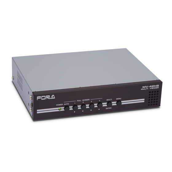
3. Panel Descriptions 3-1. Front Panel M(4) MV - 42HS MULTI VIEWER FULL SCREEN POWER AUTO MULTI MENU ENTER (1) (2) M(5) Name Description Lights green when the power of the unit is turned on. Connect the DC12V IN connector to the power source to turn POWER LED the unit on. -
Page 12: Rear Panel
3-2. Rear Panel (10) RS-232C REMOTE/TALLY ANALOG COMPOSITE IN REF IN LTC IN DC12V IN HD/SD-SDI IN HD-SDI OUT DVI-D OUT SER.NO. Name Description RS-232C connector for title settings and remote control. RS-232C See section 8 “RS-232C Interface” for detail. HD/SD-SDI IN 1 to 4 Used to input HD/SD-SDI signal (auto format detection). -
Page 13: Ref In (External Reference Signal): Mv-42If/Ifa Option
3-2-1. REF IN (External Reference Signal): MV-42IF/IFA Option Combination of MV-42HS output format and external reference signal that can be synchronized are shown in the table below. The output signal will free-run if no external reference signal is input or the input reference signal does not match with the output format. -
Page 14: Operation
4. Operation 4-1. Operation at Startup When the power is turned on, the MV-42HS starts up in the last layout before the power was turned off. However, if the MV-42HS was turned off while it was displaying a menu, the screen display starts in the last layout before displaying menus. -
Page 15: Displaying In Full Screen
4-4. Displaying in Full Screen To display your desired channel in full screen, press the corresponding button from among buttons 1 to 4. For instance, to view channel 3 in full screen, press button 3. MV - 42HS MULTI VIEWER FULL SCREEN POWER AUTO... -
Page 16: Gpi Control: Mv-42If/Ifa Option
5. GPI Control: MV-42IF/IFA Option The MV-42HS with the MV-42IF/IFA option installed can control full screen channel, full/multi-channel screen selection, tally indication, internal clock correction, and alarm resets using up to 8 “Make-contact” inputs. Tally input enables 2-color (red and green) selectable border displays around windows. -
Page 17: Full Screen Automatic Switching (Auto)
[Input Connector] The figure on the right depicts the MV-42HS circuit for each 330Ω input pin. Photo coupler Input pin 5-1-1. Full Screen Automatic Switching (AUTO) When the input pulse signal level drops, the channel displayed in full screen switches. (The pulse width should be 100 ms or more.) -
Page 18: Screen Display
6. Screen Display 6-1. Display Mode The MV-42HS allows you to select 3 display modes. The display mode can be set for full screen and multi-channel screen separately in the DISPLAY MODE menu. In multi-channel screens, windows can be set to different modes. - Page 19 <ASPECT 2 Mode> Title, audio level meter, and time code displays are displayed on the video image. The aspect ratio of the input signal is retained. Tally frame 23:59:59:29 Border Video image Black bar Source 1 Displaying a 4:3 signal in ASPECT 2 mode <FIT SCREEN Mode>...
-
Page 20: Display Examples
6-2. Display Examples 6-2-1. Quad Screen (QUAD) Screen appears as shown below when WINDOWs 1 to 4 are set as follows; Input video DISPLAY MODE AUD LVL Tally WINDOW 1 16:9 ASPECT 1 WINDOW 2 FIT SCREEN WINDOW 3 ASPECT 2 WINDOW 4 None FIT SCREEN... -
Page 21: Right/Left Split-Screen (H2)
6-2-2. Right/left Split-screen (H2) Screen appears as shown below when WINDOWs 1 to 2 are set as follows; Input video DISPLAY MODE AUD LVL Tally WINDOW 1 16:9 ASPECT 2 WINDOW 2 FIT SCREEN 23:59:59:29 Source 1 Source 2 Reference Name Description Full screen Multi screen... -
Page 22: Date/Time Display: Mv-42If/Ifa Option
6-3. Date/Time Display: MV-42IF/IFA Option The MV-42IF/IFA option allows you to display Date and Time on the screen. 6-3-1. Date Display Settings Date display modes can be selected. This setting is common to full screen and multi-channel screen displays. * See section 7-6-1-2. “SET (DATE/TIME)” for details. Ex. -
Page 23: Tally
6-4. Tally Tally detection can be turned on to use the tally feature. See section 7-3-1-4. “TALLY SETUP (SYSTEM - VIDEO)” for details on settings. 6-4-1. Tally Indication Turning tally detection and tally indication on enables an 8-pixel wide tally frame display around the outer window borders. -
Page 24: Crop
6-5. Crop The active picture area can be set for the input display to adjust the black area produced by converting images to 4:3 or 16:9 and resize the video image to best fit the output screen. See section 7-3-1-2. “CROP SETUP (SYSTEM - VIDEO)” for details on settings. The crop function can be enabled or disabled for full screen and multi-channel screen display separately. -
Page 25: Audio Level Metering
6-6. Audio Level Metering Audio level metering for up to 8 audio channels of embedded HD/SD-SDI audio signals. (1) Peak level Peak levels can be set in the range of -30 to 0 dBFS. If the level bar rises above the peak level, the exceeded part is displayed in red. (2) Reference level Reference levels can be set in the range of -60 to -1 dBFS. - Page 26 2) Setting Audio level meter bar width Select a bar width from 8, 12, and 16 (pixel) in the AUD LVL METER WIDTH menu. The bar widths will change but the spacing between bars will not change. 3) Selecting display style Select whether to display audio level meters on one side or both sides, and how many level meters to display in the AUD LVL METER DISP FORM menu.
- Page 27 5) Selecting audio channels for audio level metering The AUD LVL METER START CH1 and CH2 menus allows you to select which audio channel to start display audio level meters for the first half and last half sets of meters. * Only odd-numbered channels can be selected.
-
Page 28: Video Signal Loss Alarm
6-7. Video Signal Loss Alarm The MV-42HS can detect video signal loss and display an alarm message in the area for the title display. ⚫ When video signal loss is detected in CH1 while CH1 is assigned to a window that is being displayed in full screen. -
Page 29: Ancillary Time Code (Atc) Display
6-8. Ancillary Time Code (ATC) Display The ancillary time code (ATC) in an HD-SDI or SD-SDI signal can be displayed. The detection mode can be selected from LTC and VITC in a menu. See section 7-3-1-3. “TC DETECT FORMAT (SYSTEM - VIDEO)” for details. Ancillary time code HH:MM:SS:FF Source 1... -
Page 30: Video Clip Mode
6-9. Video Clip Mode This menu allows you to clip video signal levels when turned ON, and monitor super white and super black levels when turned OFF. Mode selections can be made in a menu. See section 7-3-1 “VIDEO SETUP 1/2 to 2/2 (SYSTEM)” for details. 6-9-1. -
Page 31: Menu Operation
7. Menu Operation Submenus in the main menu are available for various settings. * The “>” displayed next to a menu item in menu windows indicates that the item has a submenu or submenus. 7-1. Main Menu Hold down the MENU button at least 2 seconds to open the Main menu. MAIN MENU 1/2 MAIN MENU 2/2 DISPLAY... - Page 32 Item Setting Description Refer to VERSION Version information display 7-5.VERSION COMPOSITE Displays whether the MV-42AI option is installed or OPTION (MV-42AI not. option) * DATE/TIME settings INTERFACE LAN settings OPTION 7-6. INTERFACE (MV-42IF/IFA OPTION GPI settings option) * GENLOCK settings * [NONE] indicates: The option is not installed.
- Page 33 ◆ Menu structure MAIN MENU DISPLAY FULL SCREEN DISPLAY TIME DISPLAY MODE CROP ENABLE BORDER ENABLE BORDER WIDTH BODER COLOR TITLE ENABLE TITLE SIZE TITLE COLOR TITLE TRANSPARENCY TITLE EDGE TITLE EDGE COLOR TITLE EDGE TRANSPARENCY TITLE POSITION TIME CODE ENABLE TIME CODE SIZE TIME CODE POSITION AUD LVL METER ENABLE...
- Page 34 ⚫ Optional menus MAIN MENU COMPOSITE OPTION INTERFACE OPTION DATE/TIME FULL SCREEN DATE SELECT TIME SELECT SIZE POSITION MULTI CH SCREEN DATE SELECT TIME SELECT SIZE POSITION DATE FORMAT 11/01/01 00:00:00 IP ADDRESS SUBNET MASK GATEWAY PORT MAC ADDRESS GPI 1~8 GENLOCK H PHASE V PHASE...
-
Page 35: Save Change
7-1-1. SAVE CHANGE? Pressing the MENU button while displaying the main menu page after any change has been made in menus displays the message as shown below. SAVE CHANGE? CANCEL MV - 42HS MULTI VIEWER FULL SCREEN POWER AUTO MULTI MENU ENTER ↓... -
Page 36: Display
7-2. DISPLAY In the main menu, move the cursor to DISPLAY > and press the ENTER button. The DISPLAY page as shown below will be displayed. DISPLAY FULL SCREEN > MULTI CH SCREEN > TITLE TEXT > MV - 42HS MULTI VIEWER FULL SCREEN POWER... -
Page 37: Full Screen
7-2-1. FULL SCREEN Allows you to set parameters for full screen displays. 7-2-1-1. FULL SCREEN SETUP 1/8 to 8/8 FULL SCREEN SETUP 1/8 FULL SCREEN SETUP 5/8 DISPLAY TIME : 5sec TIME CODE ENABLE : OFF DISPLAY MODE : ASPECT 1 TIME CODE SIZE : 7 (32*64) TIME CODE POSITION... - Page 38 ◆ Setting Items Item Setting range Description Allows you to set the full screen display duration to automatically return to a multi-channel screen. DISPLAY TIME (Set between 1 and 60 seconds. OFF disables 1 to 60 sec the automatic screen display change.) ASPECT 1 Allows you to select full screen display mode.
- Page 39 Item Setting range Description 1 + 1 AUD LVL Allows you to select how to arrange audio level meters in full METER DISP 2 + 2 screen displays. FORM 4 + 4 LEFT-ALGND AUD LVL Allows you to select how to allocate audio level meters of METER ORDER respective audio channels in full screen displays.
-
Page 40: Title Color / Title Edge Color (Full)
7-2-1-2. TITLE COLOR / TITLE EDGE COLOR (FULL) The TITLE COLOR (FULL) / TITLE EDGE COLOR (FULL) menu allows you to change the color of the title and title edge in full screen displays. TITLE COLOR (FULL) TITLE EDGE COLOR (FULL) : 255 GREEN : 255... -
Page 41: Multi Ch Screen
7-2-2. MULTI CH SCREEN Allows you to set multi-channel screen parameters. 7-2-2-1. MULTI CH SCREEN SETUP 1/8 to 8/8 MULTI CH SCREEN SETUP 5/8 MULTI CH SCREEN SETUP 1/8 DISPLAY TYPE : QUAD TIME CODE ENABLE > SOURCE SELECT > TIME CODE SIZE >... - Page 42 ◆ Setting Items Item Description Reference Allows you to select a QUAD type of multi-channel screen display. DISPLAY TYPE QUAD: Quad screen H2: Horizontally split (right/left split) screen. SOURCE Allows you to select source video 7-2-2-2. SOURCE SELECT (MULTI) SELECT signal to display.
-
Page 43: Source Select (Multi)
7-2-2-2. SOURCE SELECT (MULTI) Move the cursor to SOURCE SELECT > in the MULTI CH SCREEN SETUP menu, and press the ENTER button. The SOURCE SELECT (MULTI) menu as shown below will be displayed. This menu allows you to change source video signals to be displayed in windows in multi-channel screen displays. -
Page 44: Display Mode (Multi)
7-2-2-3. DISPLAY MODE (MULTI) Move the cursor to DISPLAY MODE > in the MULTI CH SCREEN SETUP menu, and press the ENTER button. The DISPLAY MODE menu as shown below will be displayed. This menu allows you to change the display mode for each window. DISPLAY MODE (MULTI) WINDOW 1 : ASPECT 1 WINDOW 2 : ASPECT 1... -
Page 45: Crop Enable (Multi)
7-2-2-4. CROP ENABLE (MULTI) Move the cursor to CROP ENABLE > in the MULTI CH SCREEN SETUP 1/7 menu, and press the ENTER button. The CROP ENABLE menu as shown below will be displayed. This menu allows you to enable or disable cropping in multi-channel screen displays. CROP ENABLE (MULTI) WINDOW 1 : ON WINDOW 2 : ON... -
Page 46: Border Enable (Multi)
7-2-2-5. BORDER ENABLE (MULTI) Move the cursor to BORDER ENABLE > in the MULTI CH SCREEN SETUP menu, and press the ENTER button. The BORDER ENABLE menu as shown below will be displayed. This menu allows you to enable or disable border display for windows in multi-channel screen displays. -
Page 47: Border Width (Multi)
7-2-2-6. BORDER WIDTH (MULTI) Move the cursor to BORDER WIDTH > in the MULTI CH SCREEN SETUP menu, then press the ENTER button. The BORDER WIDTH menu as shown below will be displayed. This menu allows you to set border widths for windows in multi-channel screen displays. BORDER WIDTH (MULTI) WINDOW 1 - T: 1 B : 1 L: 1 R: 1 WINDOW 2 - T: 1 B : 1 L: 1 R: 1... -
Page 48: Border Color (Multi)
7-2-2-7. BORDER COLOR (MULTI) Move the cursor to BORDER COLOR > in the MULTI CH SCREEN SETUP menu, then press the ENTER button. The BORDER COLOR menu as shown below will be displayed. This menu allows you to set border colors for windows in multi-channel screen displays. BORDER COLOR (MULTI) WINDOW 1 - R: 128 G: 128 B: 128 WINDOW 2 - R: 128 G: 128 B: 128... -
Page 49: Title Enable (Multi)
7-2-2-8. TITLE ENABLE (MULTI) Move the cursor to TITLE ENABLE > in the MULTI CH SCREEN SETUP menu, then press the ENTER button. The TITLE ENABLE menu will be displayed. This menu allows you to enable or disable title displays for windows in multi-channel screen displays. TITLE ENABLE (MULTI) WINDOW 1 : ON WINDOW 2 : ON... -
Page 50: Title Size (Multi)
7-2-2-9. TITLE SIZE (MULTI) Move the cursor to TITLE SIZE > in the MULTI CH SCREEN SETUP menu, then press the ENTER button. The TITLE SIZE menu as shown below will be displayed. This menu allows you to set the title sizes of windows in multi-channel screen displays. TITLE SIZE (MULTI) WINDOW 1 : 5 (24*48) WINDOW 2 : 5 (24*48) -
Page 51: Title Color (Multi)
7-2-2-10. TITLE COLOR (MULTI) Move the cursor to TITLE COLOR > > in the MULTI CH SCREEN SETUP menu, then press the ENTER button. The TITLE COLOR menu as shown below will be displayed. This menu allows you to set the title colors of windows in multi-channel screen displays. TITLE COLOR (MULTI) WINDOW 1 : R: 255 G: 255 B: 255 WINDOW 2 : R: 255 G: 255 B: 255... -
Page 52: Title Transparency (Multi)
7-2-2-11. TITLE TRANSPARENCY (MULTI) Move the cursor to TITLE TRANSPARENCY > in the MULTI CH SCREEN SETUP menu, then press the ENTER button. The TITLE TRANSPARENCY menu will be displayed. This menu allows you to set the title transparency for windows in multi-channel screen displays. -
Page 53: Title Edge (Multi)
7-2-2-12. TITLE EDGE (MULTI) Move the cursor to TITLE EDGE >in the MULTI CH SCREEN SETUP menu, then press the ENTER button. The TITLE EDGE menu as shown below will be displayed. This menu allows you to set title edge settings for windows in multi-channel screen displays. TITLE EDGE (MULTI) WINDOW 1 : MAT WINDOW 2 : MAT... -
Page 54: Title Edge Color (Multi)
7-2-2-13. TITLE EDGE COLOR (MULTI) Move the cursor to TITLE EDGE COLOR > in the MULTI CH SCREEN SETUP menu, then press the ENTER button. The TITLE EDGE COLOR menu as shown below will be displayed. This menu allows you to set the title edge colors for windows in multi-channel screen displays. -
Page 55: Title Edge Transparency (Multi)
7-2-2-14. TITLE EDGE TRANSPARENCY (MULTI) Move the cursor to TITLE EDGE TRANSPARENCY > in the MULTI CH SCREEN SETUP menu, then press the ENTER button. The TITLE EDGE TRANSPARENCY menu will be displayed. This menu allows you to set the title edge transparency for windows in multi-channel screen displays. -
Page 56: Title Position (Multi)
7-2-2-15. TITLE POSITION (MULTI) Move the cursor to TITLE POSITION > in the MULTI CH SCREEN SETUP menu, then press the ENTER button. The TITLE POSITION menu as shown below will be displayed. This menu allows you to set the title positions for windows in multi-channel screen displays. -
Page 57: Time Code Enable (Multi)
7-2-2-16. TIME CODE ENABLE (MULTI) Move the cursor to TIME CODE ENABLE > in the MULTI CH SCREEN SETUP page, then press the ENTER button. The TIME CODE ENABLE menu as shown below will be displayed. This menu allows you to enable or disable time code displays for windows in multi-channel screen displays. -
Page 58: Time Code Size (Multi)
7-2-2-17. TIME CODE SIZE (MULTI) Move the cursor to TIME CODE SIZE > in the MULTI CH SCREEN SETUP menu, then press the ENTER button. The TIME CODE SIZE menu as shown below will be displayed. This menu allows you to change the time code display size for windows in multi-channel screen displays. -
Page 59: Time Code Position (Multi)
7-2-2-18. TIME CODE POSITION (MULTI) Move the cursor to TIME CODE POSITION > in the MULTI CH SCREEN SETUP page, then press the ENTER button. The TIME CODE POSITION menu as shown below will be displayed. This menu allows you to set the time code display position for windows in multi-channel screen displays. -
Page 60: Aud Lvl Meter Enable (Multi)
7-2-2-19. AUD LVL METER ENABLE (MULTI) Move the cursor to AUD LVL METER ENABLE > in the MULTI CH SCREEN SETUP menu, then press the ENTER button. The AUD LVL METER ENABLE menu as shown below will be displayed. This menu allows you to enable or disable audio level meter displays for windows in multi-channel screen displays. -
Page 61: Aud Lvl Meter Width (Multi)
7-2-2-20. AUD LVL METER WIDTH (MULTI) Move the cursor to AUD LVL METER WIDTH > in the MULTI CH SCREEN SETUP menu, then press the ENTER button. The AUD LVL METER WIDTH menu as shown below will be displayed. This menu allows you to change the audio level meter bar widths for windows in multi-channel screen displays. -
Page 62: Aud Lvl Meter Disp Form (Multi)
7-2-2-21. AUD LVL METER DISP FORM (MULTI) Move the cursor to AUD LVL METER DISP FORM > in the MULTI CH SCREEN SETUP menu, then press the ENTER button. The AUD LVL METER DISP FORM menu as shown below will be displayed. This menu allows you to select how to display audio level meters for windows in multi-channel screen displays. -
Page 63: Aud Lvl Meter Order (Multi)
7-2-2-22. AUD LVL METER ORDER (MULTI) Move the cursor to AUD LVL METER ORDER > in the MULTI CH SCREEN SETUP menu, then press the ENTER button. The AUD LVL METER ORDER menu as shown below will be displayed. This menu allows you to select how to align the audio channel level meters for windows in multi-channel screen displays. -
Page 64: Aud Lvl Meter Start Ch1/2 (Multi)
7-2-2-23. AUD LVL METER START CH1/2 (MULTI) Move the cursor to AUD LVL METER START CH1/2 > in the MULTI CH SCREEN SETUP menu, then press the ENTER button. The AUD LVL METER START CH1/2 menu as shown below will be displayed. This menu allows you to select the audio channel from which to start audio level meter displays for windows in multi-channel screen displays. -
Page 65: Tally Enable (Multi)
7-2-2-24. TALLY ENABLE (MULTI) Move the cursor to TALLY ENABLE > in the MULTI CH SCREEN SETUP menu, then press the ENTER button. The TALLY ENABLE (MULTI) menu as shown below will be displayed. This menu allows you to select whether to display tally frames for windows in multi-channel screen displays. -
Page 66: Title Text
7-2-3. TITLE TEXT Press the ENTER button while the cursor is on TITLE TEXT > in the DISPLAY menu to display the TITLE TEXT menu allowing title text settings for each video input SOURCE. TITLE TEXT SOURCE 1 > SOURCE 2 > SOURCE 3 >... -
Page 67: Source 1 To 4 (Title Text)
7-2-3-1. SOURCE 1 to 4 (TITLE TEXT) Move the cursor to SOURCE 1 >, SOURCE 2 >, SOURCE 3 >, or SOURCE 4 >, then press the ENTER button. The corresponding SOURCE (TITLE TEXT) menu will be displayed. The menu allows you to set title text for the video input SOURCE. SOURCE 1 (TITLE TEXT) Title text Source 1... -
Page 68: System
7-3. SYSTEM In the main menu, move the cursor to SYSTEM > then press the ENTER button. The SYSTEM menu as shown below will be displayed. SYSTEM 1/2 SYSTEM 2/2 OUTPUT FORMAT : 1080/59.94i INPUT > VIDEO SETUP > AUDIO SETUP > FRONT PANEL LOCK : OFF * The above settings are factory default. -
Page 69: Video Setup 1/2 To 2/2 (System)
7-3-1. VIDEO SETUP 1/2 to 2/2 (SYSTEM) In the SYSTEM menu, move the cursor to VIDEO SETUP > then press the ENTER button. The VIDEO SETUP menu as shown below will be displayed. VIDEO SETUP 1/2 (SYSTEM) VIDEO SETUP 2/2 (SYSTEM) AUTO SEQUENCE TIME : 1sec BACK COLOR >... -
Page 70: Back Color (System - Video)
10. MENU Returns to the VIDEO SETUP (SYSTEM) menu. ◆ Setting Items Item Setting range Description Allows you to set a screen background color that GREEN 0 to 255 appears around windows displaying video images output from the MV-42HS. BLUE... -
Page 71: Crop Setup (System - Video)
0 to 1920 SOURCE 4 each SOURCE video. RIGHT 0 to 1920 IMPORTANT Although any value can be selected, the cropped area size may not change according to their settings, due to the MV-42HS restricting retained image sizes to 120x80 pixels. -
Page 72: Tc Detect Format (System - Video)
7-3-1-3. TC DETECT FORMAT (SYSTEM - VIDEO) In the VIDEO SETUP (SYSTEM) menu, move the cursor to TC DETECT FORMAT >, then press the ENTER button. The TC DETECT FORMAT (SYSTEM - VIDEO) menu allowing time code detection settings for each video input SOURCE as shown below will be displayed. -
Page 73: Tally Setup (System - Video)
7-3-1-4. TALLY SETUP (SYSTEM - VIDEO) In the VIDEO SETUP (SYSTEM) menu, move the cursor to TALLY SETUP >, then press the ENTER button. The TALLY SETUP (SYSTEM - VIDEO) menu as shown below will be displayed. This menu allows you to change parameters for tally detection and display. See section 6-4. -
Page 74: Audio Setup (System)
7-3-2. AUDIO SETUP (SYSTEM) In the SYSTEM menu, move the cursor to AUDIO SETUP >, then press the ENTER button. The AUDIO SETUP menu as shown below will be displayed. See section 6-6. “Audio Level Metering” for details. AUDIO SETUP (SYSTEM) AUDIO REF LEVEL : -20 AUDIO PEAK LEVEL: -10 * The above settings are factory default. -
Page 75: Input (System)
7-3-3. INPUT (SYSTEM) In the SYSTEM menu, move the cursor to INPUT >, then press the ENTER button. The INPUT menu as shown below will be displayed. This menu allows you to select input signals and view the currently input signal formats. * Signals can be selected only when the MV-42AI option is installed. - Page 76 ◆ Input Format Signal selection Input format display Description NO SIGNAL No input signal, or unsupported input signal 1080/60i 1080/60i or 1080/30PsF 1080/59.94i 1080/59.94i or 1080/29.97PsF 1080/50i 1080/50i or 1080/25PsF 1080/24PsF 1080/23.98PsF 1080/30p 1080/29.97p 1080/25p 1080/24p 1080/23.98p The same format as shown at left. 720/60p 720/59.94p 720/50p...
-
Page 77: Loss
7-4. LOSS In the MAIN MENU, move the cursor to LOSS >, then press the ENTER button. The LOSS menu as shown below will be displayed. See section 6-7. “Video Signal Loss Alarm” for details. LOSS LOSS DETECT : OFF LOSS RESET : NONE LOSS RESET TIME... -
Page 78: Version
7-5. VERSION In the MAIN MENU, move the cursor to VERSION, then press the ENTER button. The VERSION menu as shown below will be displayed. This menu allows you to verify the MV-42HS version information. VERSION FPGA : 01.00 SOFT : 01.00... -
Page 79: Interface Option
7-6. INTERFACE OPTION In the MAIN MENU, move the cursor to INTERFACE OPTION: INSTALLED > while the MV-42IF/IFA option is installed, then press the ENTER button. The INTERFACE OPTION menu as shown below will be displayed. This menu will be displayed only if the MV-42IF/IFA option is installed. -
Page 80: Date/Time (Interface Option)
7-6-1. DATE/TIME (INTERFACE OPTION) In the INTERFACE OPTION menu, move the cursor to DATE/TIME >, then press the ENTER button. The DATE/TIME (INTERFACE OPTION) menu as shown below will be displayed. * See section 6-3. “Date/Time Display: MV-42IF/IFA Option” for details. DATE/TIME (INTERFACE OPTION) FULL SCREEN >... -
Page 81: Full / Multi Ch Screen (Date/Time)
7-6-1-1. FULL / MULTI CH SCREEN (DATE/TIME) In the DATE/TIME (INTERFACE OPTION) menu, move the cursor to FULL SCREEN > or MULTI CH SCREEN>, then press the ENTER button. The menu as shown below will be displayed. * See section 6-3. “Date/Time Display: MV-42IF/IFA Option” for details. FULL SCREEN (DATE/TIME) MULTI CH SCREEN (DATE/TIME) :... -
Page 82: Set (Date/Time)
7-6-1-2. SET (DATE/TIME) In the DATE/TIME (INTERFACE OPTION) menu, move the cursor to SET >, then press the ENTER button. The menu as shown below will be displayed. * See section 6-3. “Date/Time Display: MV-42IF/IFA Option” for details. SET (DATE/TIME) DATE FORMAT :... -
Page 83: Lan (Interface Option)
7-6-2. LAN (INTERFACE OPTION) In the INTERFACE OPTION menu, move the cursor to LAN >, then press the ENTER button. The menu as shown below will be displayed. * See section 9. “LAN Interface: MV-42IF/IFA Option” for details. LAN (INTERFACE OPTION) 1/2 LAN (INTERFACE OPTION) 2/2 :... -
Page 84: Gpi (Interface Option)
7-6-3. GPI (INTERFACE OPTION) In the INTERFACE OPTION menu, move the cursor to GPI >, then press the ENTER button. The menu as shown below will be displayed. * See section 5. “GPI Control: MV-42IF/IFA Option” for details. GPI (INTERFACE OPTION) GPI1 :... -
Page 85: Genlock (Interface Option)
7-6-4. GENLOCK (INTERFACE OPTION) In the INTERFACE OPTION menu, move the cursor to GENLOCK >, then press the ENTER button. The menu as shown below will be displayed. GENLOCK (INTERFACE OPTION) : H PHASE 0CLOCK : V PHASE 0LINE LOCK STATUS : LOCKED REFERENCE :... -
Page 86: Rs-232C Interface
Asynchronous, Full-duplex mode Baud rate 38,400[bps] Data length 8 [bit] Stop bit 1 [bit] Parity None Flow control None IMPORTANT DSR/DTR and RTS/CTS are looped back in the MV-42HS. Use RS-232C straight cables to connect to a PC or other devices. -
Page 87: Rs-232C Connection Example
Unused Unused Unused Unused Case Case 9-pin D-sub female 9-pin D-sub female IMPORTANT Use straight cables. (The wiring and connector will depend on the type of the PC to be connected.) DSR/DTR and RTS/CTS are looped back in the MV-42HS. -
Page 88: Lan Interface: Mv-42If/Ifa Option
In such case, wait awhile and reconnect, or reboot the MV-42HS and reconnect. - Host address bits in the subnet mask for the IP address may not all be set to 0 or 1. -
Page 89: Notes On The Lan Interface
3) The MV-42HS can establish one connection to one PC via LAN. 4) MV-42HS control from a PC is enabled when a connection between the two units is established. Release the port on the MV-42HS when terminating control from the PC. -
Page 90: Command Protocol Format
Source channel no. 1-4 01-04 End code IMPORTANT The MV-42HS sends a response or message when receiving a command. Do not send the next command before receiving the response or the message transmitted by the MV-42HS. Otherwise, the command cannot be read properly. -
Page 91: Response Message
10-2. Response Message When you send commands to the MV-42HS, you will receive response messages from the MV-42HS. ◆ Normal reception A Message in the following format will be returned after normal reception and processing. Byte Parameter Command Description Message code End code ◆... -
Page 92: Control Commands / Status Request Commands
10-3. Control Commands / Status Request Commands 10-3-1. Full Screen Display (SDF) Displays a specified source video signal in full screen. Byte Parameter Command Description Command code Input source channel Source channel no. 1-4 01-04 End code 10-3-2. Multi Channel Screen Display (SDS) Displays multiple source signals in the selected multi-channel screen. -
Page 93: Output Screen Status Request (Rdp)
10-3-4. Output Screen Status Request (RDP) Requests the current status of output images. ◆ Status Request Command Byte Parameter Command Description Command code End code ◆ Response Message Byte Parameter Command Description Message code Normal display mode Display mode MENU display mode Full screen Screen display * Fixed to “0”... -
Page 94: Video Source Text Request (Rti)
Video source 01-04 Title text Up to 16 characters ASCII code (1 byte/character) End code 10-3-8. Control Setting Backup (SBK) Stores the control settings to the MV-42HS. Byte Parameter Command Description Command code Reserved End code 10-3-9. Tally Control (STO) Controls tallies if command is selected for tally input. -
Page 95: Internal Clock Settings (Sdt) : Mv-42If/Ifa Option
10-3-10. Internal Clock Settings (SDT) : MV-42IF/IFA Option Sets the date and time for the internal clock. Settings will be saved if the command is properly received and processed. * The 10-3-8. “Control Setting Backup (SBK)” command is not needed to save these settings. The “ERR005”... -
Page 96: Troubleshooting
11. Troubleshooting If any of the following problems occur while operating the MV-42HS, before assuming a unit malfunction has occurred, follow the troubleshooting procedures below to see if the problem can be corrected. IMPORTANT If a problem remains uncorrected after performing the procedures below, turn the unit off and then on again. -
Page 97: Specifications And Dimensions
12V DC (DC jack) * AC adaptor can be separately purchased. Use an AC adaptor that meets the following requirements. Output voltage: 12V DC, Output ampere: 2A, Inrush current: 30A, Connecter: JEITA RC-5320A Standard Voltage Class4 * The MV-42HS connecter is HOSIDEN-produced HEC3800-01-010. Center positive voltage. - Page 98 Weight 1.16 kg Dimensions (W) x (H) x (D)mm EIA 1 RU Half Rack 480 (W) (Including single or dual rack mount brackets) Accessories Quick Setup Guide, and CD-ROM (Operation manuals (PDF)) Consumables Cooling fan: P1472 Replace every 3 yeaars (at room temp.) MV-42AI (Analog Composite Input Card) Option Video Input 4 inputs (Select analog composite or SDI input for each input channel...
-
Page 99: External Dimensions
12-2. External Dimensions (All dimensions in mm.) MV-42HS MULTI VIEWER FULL SCREEN POWER AUTO MULTI MENU ENTER... -
Page 100: Rack Mounted Mv-42Hs(S)
12-2-1. Rack Mounted MV-42HS(s) (All dimensions in mm) ◆ 2 units installed MV-42HS MV-42HS MULTI VIEWER MULTI VIEWER FULL SCREEN FULL SCREEN POWER AUTO MULTI MENU POWER AUTO MULTI MENU ENTER ENTER ◆ 1 unit installed MV-42HS MULTI VIEWER FULL SCREEN... -
Page 101: Index
Q E Quad screen (QUAD) ........20 External Dimensions ......... 99 R F Rack Mounted MV-42HS(s) ......100 FIT SCREEN Mode .......... 19 Rear Panel ............12 Front Panel ............11 Reference level..........25 FULL / MULTI CH SCREEN (DATE/TIME) . 81 Response Message ..........91... - Page 102 Right/left split-screen (H2) ....... 21 TIME CODE ENABLE (MULTI) ....57 RS-232C Connection Example ......87 TIME CODE POSITION (MULTI) ....59 RS-232C Connector .......... 86 TIME CODE SIZE (MULTI) ......58 RS-232C Interface ..........86 TITLE COLOR (MULTI) ........ 51 RS-232C/LAN Command .........
- Page 103 Warning This equipment has been tested and found to comply with the limits for a Class A digital device, pursuant to Part 15 of FCC Rules. These limits are designed to provide reasonable protection against harmful interference when the equipment is operated in a commercial environment. This equipment generates, uses, and can radiate radio frequency energy and, if not installed and used in accordance with the instruction manual, may cause harmful interference to radio communications.
- Page 104 Tel: +1 352-371-1505 Fax: +1 714-894-5399 FOR-A Latin America and the Caribbean Miami Office Tel: +1 657-600-5759 FOR-A Latin America and the Caribbean Sao Paulo Office Tel: +55 (0)11-99913-3751 FOR-A Europe S.r.l. Via Volturno, 37, 20861 Brugherio MB, Italy Tel: +39 039-916-4811...
Need help?
Do you have a question about the MV-42HS and is the answer not in the manual?
Questions and answers