Table of Contents
Advertisement
Quick Links
Advertisement
Table of Contents

Subscribe to Our Youtube Channel
Related Manuals for iLight SCA0410


Summary of Contents for iLight SCA0410
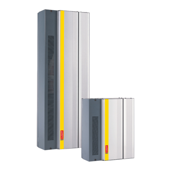
- Page 1 Installation Guide SCA0410 & SCA1210 Wall Mounted Adaptive Dimming Controllers...
-
Page 2: Table Of Contents
PLEASE RETAIN THIS MANUAL FOR FUTURE REFERENCE The information contained in this product manual is correct at the time of publication, however iLight reserve the right to make changes to the content of this product manual without prior notice. The latest revision of this manual can be downloaded by visiting our website at www.ilight.co.uk... -
Page 3: Installation
(see right, bottom). • Allow adequate space for future maintenance of the unit. Do not install in a location that will later be inaccessible. iLight SCA0410 & SCA1210 Installation Guide Document 9850-000927-00... -
Page 4: Load Connections
(~W / A) SCA0410 Single Phase Leading & Trailing-edge, mains & LV (tungsten, 2300W / 10A only halogen). SCA1210 Single or Leading & Trailing-edge, mains & LV (tungsten, 2300W / 10A Three Phase halogen). iLight SCA0410 & SCA1210 Installation Guide Document 9850-000927-00... - Page 5 Connecting the Supply SCA0410 - Single Phase Supply Live (L) Neutral (N) Earth (E) SCA1210 - Three Phase Supply SCA1210 - Single Phase Supply Live (L1) Live (L2) Note: For single phase wiring Live (L3) Live the live supply cable will...
-
Page 6: Network Connections
Network Connections Network Cable Topology The iLight Network is of CAN bus (Controller Area Network) standard. A maximum of 100 devices can be added to the network on a single run. NOTE: Device quantity can be increased with a BN-2-D Network Bridge/Repeater unit. - Page 7 Connection to the network Connections for the iLight network are located on the CPU card at the bottom of the unit with the cover removed. Maximum segment distance: 500m (1640 ft). Devices per segment: 100 (without bridge or repeater) Consult iLight for information on alternative cable types.
-
Page 8: Service Switches And Leds
It is still possible to enter Diagnostic mode if a Source Controller is in iCANnet error status. iLight SCA0410 & SCA1210 Installation Guide Document 9850-000927-00... -
Page 9: Overide Mode
When the Source Controller is placed into override mode it will no longer respond to commands sent over the iLight network. Override mode can also be used to restore power to outputs if control is lost or temporarily removed to allow lighting to remain on until control is restored. -
Page 10: Rs485 Connection
Source Controllers have an RS485 port located on the CPU PCB which allows for direct serial integration with the iLight network. If multiple Source Controllers are linked on the iLight network then only a single RS485 connection is required in order to potentially control all devices. - Page 11 RS485 Message Glossary Virtual control messages are used to control the system, and not individual devices. The message is transmitted across the iLight CAN network to all other devices. @SSxx:Axx:Fxx<cr> This message selects a scene in an area. SSxx defines the scene number, where xx is valid from 00 to 99. Scene 00 is OFF.
-
Page 12: Dmx Input Connection
Source Controllers have an RS485 port located on the CPU PCB which allows for direct serial integration with the iLight network. This port can be converted into an input connection for DMX control of the Source Controller by a lighting desk, for example. To enable DMX control a DI-1 DMX Input PCB must be fitted to the Source Controller. -
Page 13: Alarm Input Connection
When a contact closure occurs across the normally-open Alarm and 0V terminal on the Source Controller, an alarm scene is triggered which is broadcast across the iLight Network to all other devices. The default scene setting is all channels to 100%. Control Panels are also configured by default to be locked when the alarm link is in place to disable manual override of the lighting during an alarm. -
Page 14: Troubleshooting
LED on the CPU board to ping the Source Controller. This should make it appear in the search window and display a message in the iLight network monitor window. If your issue is not covered by any of the above... - Page 15 SCA0410 & SCA1210 Installation Guide Document 9850-000927-00...
- Page 16 Email: cctechsupport@signify.com www.iLight.co.uk All products manufactured by iLight are warranted to be free from defects in material and workmanship and shall conform to and perform in accordance with Seller’s written specifications. This warranty will be limited to the repair or replacement, at Seller’s discretion, of any such goods found to be defective, upon their authorized return to Seller.
Need help?
Do you have a question about the SCA0410 and is the answer not in the manual?
Questions and answers