Sign In
Upload
Download
Add to my manuals
Delete from my manuals
Share
URL of this page:
HTML Link:
Bookmark this page
Add
Manual will be automatically added to "My Manuals"
Print this page
×
Bookmark added
×
Added to my manuals
Manuals
Brands
iLight Manuals
Controller
SCI0405
Instruction manual
iLight SCI0405 Instruction Manual
Source controllers
Hide thumbs
1
2
3
4
5
6
7
8
9
10
11
12
13
14
15
16
17
18
19
20
21
22
23
24
page
of
24
Go
/
24
Contents
Table of Contents
Bookmarks
Advertisement
Quick Links
1
Table of Contents
2
Source Controllers
3
Supply and Load Connections
4
Ascii Control Messages
5
Service Switches and Leds
6
Specifications
Download this manual
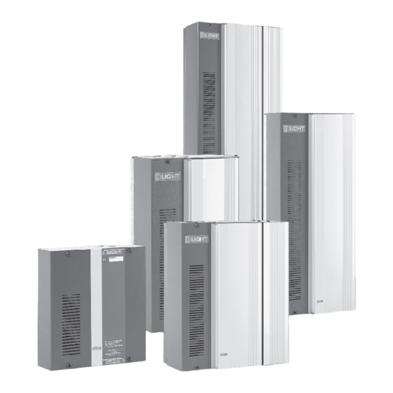
Source Controllers
- Inductive
- H F Ballast
- Power Switching
- Adaptive
- Trailing Edge
I nstruction Manual
Read this document prior to installation
Contents
2
Warning
3
Installation
5
Supply and load connections
7
iCAN Network
8
ASCII control messages
9
Typical system schematics
10
Service switches and LEDs
12
Specifications
I NTEL LI GE NT CO N T R O LS
Previous
Page
Next
Page
1
2
3
4
5
Advertisement
Need help?
Do you have a question about the SCI0405 and is the answer not in the manual?
Ask a question
Questions and answers
Related Manuals for iLight SCI0405
Controller iLight SCI1205 Instruction Manual
Source controllers (24 pages)
Controller iLight SCI1210 Instruction Manual
Source controllers (24 pages)
Controller iLight SCMD4 Installation Manual
4 universe addressable dali-2 controller (2 pages)
Controller iLight SCMD2 Installation Manual
2 universe addressable dali-2 controller (2 pages)
Controller iLight SCMR1232 Installation Manual
12 x 32a relay controller (2 pages)
Controller iLight SCMS0410 Installation Manual
4 channel x 10 amp switching controller (2 pages)
Controller iLight SCD-96-D Installation Manual
Dmx source controller (2 pages)
Controller iLight SCMH1200 Installation Manual
12 channel dinrail mount hf controller (2 pages)
Controller iLight SCA0410 Installation Manual
Wall mounted adaptive dimming controllers (16 pages)
Controller iLight SCA1210 Installation Manual
Wall mounted adaptive dimming controllers (16 pages)
Controller iLight SCMC0210 Installation Manual
2 channel 10 amp shading controller (2 pages)
This manual is also suitable for:
Sci0410
Sci1205
Sci1210
Sci1220
Print
Rename the bookmark
Delete bookmark?
Delete from my manuals?
Login
Sign In
OR
Sign in with Facebook
Sign in with Google
Upload manual
Upload from disk
Upload from URL


Need help?
Do you have a question about the SCI0405 and is the answer not in the manual?
Questions and answers