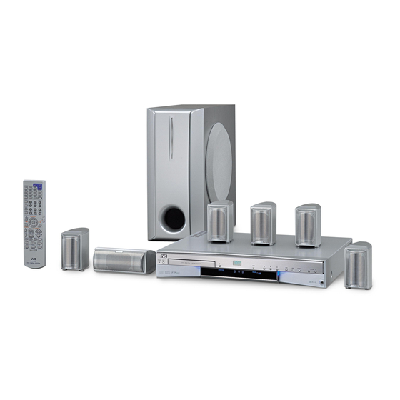
JVC TH-A75R Service Manual
Dvd digital cinema system
Hide thumbs
Also See for TH-A75R:
- Instructions manual (76 pages) ,
- Schematic diagrams (24 pages) ,
- Instructions manual (217 pages)
Advertisement
Quick Links
SERVICE MANUAL
DVD DIGITAL CINEMA SYSTEM
02
2003
21189
SP-WA75
1
Important Safety Precautions . . . . . . . . . . . . . . . . . . . . . . . . . . . . . . . . . . . . . . . . . . . . . . . . . . . . . . . . . . . 1-2
2
Disassembly method . . . . . . . . . . . . . . . . . . . . . . . . . . . . . . . . . . . . . . . . . . . . . . . . . . . . . . . . . . . . . . . . . . 1-6
3
Adjustment. . . . . . . . . . . . . . . . . . . . . . . . . . . . . . . . . . . . . . . . . . . . . . . . . . . . . . . . . . . . . . . . . . . . . . . . . . 1-16
4
Description of major ICs . . . . . . . . . . . . . . . . . . . . . . . . . . . . . . . . . . . . . . . . . . . . . . . . . . . . . . . . . . . . . . . 1-17
TH-A75R
TV
AUDIO
VIDEO/
TV SOUND
FM/AM
DVD
VCR 1
VCR
AUDIO
ANGLE
SUBTITLE
DECODE
TOP MENU
MENU
RETURN
DIGEST
SURROUND
DSP
OFF
SOUND
CONTROL
EFFECT
VCR
1
2
3
+
+
S.WFR
CENTER
TEST
Ð
Ð
TV
4
5
6
SLEEP
7
8
9
+
+
+
SETTING
SURR-L
S-BACK
SURR-R
Ð
Ð
Ð
10
0
+10
ADJUST
TV RETURN
FM MODE
100+
TA/NEWS/INFO
ON
SCREEN
DVD
RDS
PTY
PTY
ENTER
CHOICE
VFP
RDS DISPLAY
PTY SEARCH
TV VOL
CHANNEL/ZOOM
VOLUME
TV/VIDEO
MUTING
/REW
PLAY
FF/
DOWN
TUNING
UP
O.T.
STOP
PAUSE
REPLAY
REC
STROBE
MEMORY
DIMMER
STANDBY
D V D D I G I T A L C I N E M A S Y S T E M
COMPACT
RMÐSTHA75R
D I G I T A L ¥ E X
SUPER VIDEO
P R O L O G I C
DVD CINEMA SYSTEM
TABLE OF CONTENTS
COPYRIGHT © 2003 VICTOR COMPANY OF JAPAN, LTD.
SP-XSA75 and SP-XCA75
RGB
XV-THA75R
Area Suffix
B ---------------------- U.K.
E ---- Continentl Europe
EN --- Northern Europe
EV ----- Eastern Europe
SOURCE
VOLUME
PHONES
No.21189
2003/02
TH-A75R
Advertisement

Related Manuals for JVC TH-A75R


Summary of Contents for JVC TH-A75R
- Page 1 TH-A75R SERVICE MANUAL DVD DIGITAL CINEMA SYSTEM 21189 2003 TH-A75R Area Suffix B ---------------------- U.K. E ---- Continentl Europe EN --- Northern Europe EV ----- Eastern Europe SP-XSA75 and SP-XCA75 AUDIO VIDEO/ TV SOUND FM/AM VCR 1 AUDIO ANGLE SUBTITLE...
- Page 2 TH-A75R SECTION 1 Important Safety Precautions 1.1 Safety Precautions (1) This design of this product contains special hardware and exposed metal part and a known good earth ground. many circuits and components specially for safety purposes. Measure the AC voltage across the resistor with the AC For continued protection, no changes should be made to the voltmeter.
- Page 3 TH-A75R 1.5 Safety Precautions (U.K only) (1) This design of this product contains special hardware and many circuits and components specially for safety purposes. For con- tinued protection, no changes should be made to the original design unless authorized in writing by the manufacturer. Replace- ment parts must be identical to those used in the original circuits.
- Page 4 TH-A75R 1.6 Preventing static electricity Electrostatic discharge (ESD), which occurs when static electricity stored in the body, fabric, etc. is discharged, can destroy the laser diode in the traverse unit (optical pickup). Take care to prevent this when performing repairs.
- Page 5 TH-A75R 1.9 Important for laser products (1) CLASS 1 LASER PRODUCT (5) CAUTION : If safety switches malfunction, the laser is able (2) DANGER : Invisible laser radiation when open and inter to function. lock failed or defeated. Avoid direct exposure to beam.
- Page 6 TH-A75R SECTION 2 Disassembly method 2.1 Main body section 2.1.1 Removing the top cover (See Figs.1 to 4.) (1) From the right and left sides of the main body, remove the four screws A attaching the top cover. (See Figs.1 and 2.) (2) From the back side of the main body, remove the two screws B attaching the top cover.
- Page 7 TH-A75R 2.1.2 Removing the front panel assembly (See Figs.5 to 8.) • Remove the top cover. Chassis base (1) From the left side of the main body, push the section b of the slide cam using the screw driver, etc. (See Fig.5.) (2) Pull out the tray.
- Page 8 TH-A75R 2.1.3 Removing the DVD mechanism assembly (See Fig.9.) 2.1.4 Removing the DSP board (See Figs.10 and 11.) • Remove the top cover. • Remove the top cover. • Remove the front panel assembly. (1) From the top side of the main body, disconnect the card (1) From the top side of the main body, remove the barrier.
- Page 9 TH-A75R 2.1.6 Removing the main board (See Figs.12 and 13.) 2.1.7 Removing the amplifier board (See Figs.13 to 16.) • Remove the top cover. • Remove the top cover. • Remove the DSP board. (1) From the top side of the main body, disconnect the card •...
- Page 10 TH-A75R 2.1.8 Removing the fan motor (See Figs.17 and 18.) 2.1.9 Removing the power board (See Fig.19.) • Remove the top cover. • Remove the top cover. • Remove the amplifier board. • Remove the amplifier board. (1) From the top side of the main body, remove the fan cover.
- Page 11 TH-A75R 2.2 Front panel assembly section 2.3 DVD mechanism section • Remove the top cover. • Remove the top cover. • Remove the front panel assembly. • Remove the DVD mechanism assembly. 2.2.1 Removing the jack board (See Fig.1.) 2.3.1 Removing the tray (See Figs.1 and 2.)
- Page 12 TH-A75R 2.3.3 Removing the tray (See Fig.3.) 2.3.4 Removing the clamper base (See Fig.4.) (1) From the bottom side of the DVD mechanism assembly, (1) From the top side of the DVD mechanism assembly, re- disconnect the card wires from the connectors CN201 and move the four screws A attaching the clamper base.
- Page 13 TH-A75R 2.3.6 Removing the motor (See Fig.6.) 2.3.8 Removing the DVD pickup unit (See Figs.8 to 10.) • Remove the clamper base. • Remove the DVD servo board. • Remove the tray drive board. • Remove the clamper base. (1) From the top side of the DVD mechanism assembly, re- •...
- Page 14 TH-A75R DVD pickup unit Section i Section h Section i Shaft Shaft Section h Section g Fig.9 SW. actuator Section DVD traverse mechanism assembly DVD pickup unit Fig.11 Shaft Section k Section j Lead screw Fig.10 DVD pickup unit Fig.12...
- Page 15 TH-A75R 2.3.10 Removing the spindle motor board (See Figs.13 and 2.3.11 Removing the feed motor (See Figs.15 to 17.) 14.) • Remove the DVD servo board. • Remove the DVD servo board. • Remove the clamper base. • Remove the clamper base.
- Page 16 TH-A75R SECTION 3 Adjustment 3.1 Test mode (1) The AC cord is connected after pushing the STOP key and the EJECT key of a main body. (2) Change to test mode, FL indicate "TEST ??". (?? is version) At this time, TV monitor indicate the firm number "...
- Page 17 TH-A75R SECTION 4 Description of major ICs UPD784215AGC194 (IC531) : CPU • Pin layout • Pin function Pin No. Symbol Function Pin No. Symbol Function HREQ I HREQ - Not use O Slave select - +3.0V 50,51 - Not use...
- Page 18 TH-A75R 4.2 39VF0207CWHQ01 (IC524) : 2 Mbit multi-purpose flash memory • Pin layout • Block diagram SuperFlash X-Decoder Memory Address Buffers Memory Address Top view Latches Y-Decoder I/O Buffers Control Logic Data Latches DQ7 - DQ0 • Pin function Pin No.
- Page 19 TH-A75R 4.3 MM74HCT32MTC-X (IC521) : Quad 2 input OR gate • Pin layout & Block diagram • Truth table INPUTS OUTPUT (TOP VIEW) 4.4 74LCX373MTC-X (IC512,IC513) : Octal D-type latch • Pin layout • Truth table INPUTS OUTPUT X: Don't care...
- Page 20 TH-A75R 4.5 AK4586VQ (IC511) : A/D, D/A Converter • Pin layout 44 - 34 12 - 22 • Pin function Pin No. Symbol Function X'tal output pin X'tal input pin EXTCLK External master clock input pin TVDD Output buffer power supply pin, 2.7V~5.5V...
- Page 21 TH-A75R • Block diagram Audio X'tal uP I/F Oscillator MCLK Clock MCKO Generator Clock Recovery DATT LOUT1 DAIF Input Decoder DATT ROUT1 Selector DATT LOUT2 SDOUT DATT ROUT2 SDOUT BICK BICK LRCK LRCK DATT LOUT3 SDIN1 SDIN1 SDIN2 SDIN2 DATT...
- Page 22 TH-A75R 4.6 AK4382AVT-X (IC512) : D/A Converter • Pin layout • Block diagram MCLK Clock De-empahsis Divider Control CCLK Interface DZFL CDTI DZFR AOUTL+ LRCK Interpolator Modulator Audio AOUTL- Data BICK Interface SDTI AOUTR+ Interpolator Modulator AOUTR- • Pin function Pin No.
- Page 23 TH-A75R 4.7 AK93C65AF-X (IC510) : EEPROM • Pin layout 8 PIN SOP • Block diagram DATA REGISTER R/W AMPS AUTO ERASE EEPROM INSTRUCTION REGISTER INSTRUCTION DECODE, CONTROL 4096bit 256 x 16 CLOCK ADD. DECODER GENERATION BUFFERS VPP SW VREF GENERATOR •...
- Page 24 TH-A75R 4.8 AN8703FH-V (IC101) : Frontend processor for DVD • Pin layout • Pin function Pin No. Symbol Description Pin No. Symbol Description GND3 Connect to GND LPC1 Laser input terminal (DVD) RFDIFO Non connect LPC01 O Laser drive signal output terminal (DVD)
- Page 25 TH-A75R 4.9 BA15218F-XE (IC251/IC540/IC544/IC546/IC548/IC557/IC560/IC562/IC564/IC566/IC711/IC712) : Dual operational amplifier • Pin layout OUT1 1 8 Vcc -IN1 2 7 OUT2 +IN1 3 6 -IN2 VEE 4 5 +IN2 • Block diagram OTHER Q114 OUTPUT (No.21189)1-25...
- Page 26 TH-A75R 4.10 BA6664FM-X (IC251) : Motor driver • Pin layout • Block diagram DRIVER GAIN SWITCH GAIN CONTROL CURRENT SENSE AMP HALL AMP TOROUE SENSE AMP SHORT BRAKE CK Q BRAKE MODE Hall Bias 1-26 (No.21189)
- Page 27 TH-A75R • Pin function Pin No. Symbol Description Non connect Output 3 for spindle motor Non connect Output 2 for spindle motor Non connect Non connect Output 1 for spindle motor Connect to ground Positive input for hall input AMP 1...
- Page 28 TH-A75R 4.11BA5983FM-X (IC201) : 4-channel driver • Block diagram STAND BY Level Shift Level Shift Level Shift Level Shift STAND BY CH1/2/3 • Pin function Pin No. Symbol Description Pin No. Symbol Description VO4(-) O Inverted output of CH4 BIAS IN...
- Page 29 TH-A75R 4.12BA7603F-X (IC211/IC221) : Video signal switcher • Pin layout & Block diagram OUTPUT 16 15 14 13 12 SWa,SWb,SWc: Clamp inputs 4.13 BD4740G-W (IC272) : Reset • Pin layout • Block diagram Vout Vout Vref (No.21189)1-29...
- Page 30 TH-A75R 4.14 DSPC56367PV150 (IC521) : DSP • Pin layout • Block diagram MEMORY EXPANSION AREA PROGRAM HOST ESAI TRIPLE X MEMORY /INSTR. Y MEMORY (SPDIF Tx) INTER- INTER- TMER INTER- CACHE INTER-FA FACE FACE FACE 3K x 24 13K x 24...
- Page 31 TH-A75R • Pin function Pin No Symbol Function SCK/SCL I/O SPI serial clock / I2C serial clock SS/HA2 SPI slave select / I2C slave address 2 HREQ I/O Host request SDO0/SDO0_1 Serial data output 0 SDO1/SDO1_1 Serial data output 1...
- Page 32 TH-A75R Pin No Symbol Function FSR_1 I/O Frame sync for receiver SCKR_1 I/O Receiver serial clock_1 PINIT/NMI PLL initial / Nonmaskable interrupt Transfer acknowledge Bus request I/O Bus busy VCCC Bus control power GNDC Bus control ground Write enable Read enable...
- Page 33 TH-A75R 4.15 GP1FA351RZ (J5521) : Fiber optic receiver • Pin layout • Block diagram Comp & Output circuit 4.16 GP1UM271XK (IC402) : IR detecting unit for remote control Com- Demodu- Integra- para- Limiter B.P.F lator GND Vcc Vout 4.17 IS63LV102410K-X (IC525/IC526/IC527) : SRAM •...
- Page 34 TH-A75R 4.18 K4S643232E-TC60 (IC505) : 512K x 32 bit x 4 banks synchronous DRAM • Pin layout • Block diagram Data Input Register Bank Select LDQM 512K x 32 512K x 32 512K x 32 512K x 32 Column Decoder Latency &...
- Page 35 TH-A75R • Pin function Pin No. Symbol Function Power for the input buffers and core logic. Data input/output are multiplexed on the same pin. VDDQ Isolated power supply for the output buffers to provide improved noise immunity. DQ1,DQ2 Data inputs/outputs are multiplexed on the same pins.
- Page 36 TH-A75R Pin No. Symbol Function 53,54 DQ29,DQ30 Data inputs/outputs are multiplexed on the same pins. VDDQ Isolated power supply for the output buffers to provide improved noise immunity. DQ31 Data input/output are multiplexed on the same pin. This pin is recommended to be left no connection on the device.
- Page 37 TH-A75R 4.19 K4S643232E-TC70 (IC505) : 512K x 32 bit x 4 banks synchronous DRAM • Pin layout • Block diagram Data Input Register Bank Select LDQM 512K x 32 512K x 32 512K x 32 512K x 32 Column Decoder Latency &...
- Page 38 TH-A75R • Pin function Pin No. Symbol Function Power for the input buffers and core logic. Data input/output are multiplexed on the same pin. VDDQ Isolated power supply for the output buffers to provide improved noise immunity. DQ1,DQ2 Data inputs/outputs are multiplexed on the same pins.
- Page 39 TH-A75R Pin No. Symbol Function 53,54 DQ29,DQ30 Data inputs/outputs are multiplexed on the same pins. VDDQ Isolated power supply for the output buffers to provide improved noise immunity. DQ31 Data input/output are multiplexed on the same pin. This pin is recommended to be left no connection on the device.
- Page 40 TH-A75R 4.20 LA73054-X (IC231) : Video driver • Pin layout & Block diagram DRIVER DRIVER DRIVER DRIVER DRIVER DRIVER LPF2 LPF1 2Step Amp1 LPF2 LPF1 LPF2 LPF1 2Step Amp4 LPF1 SYNC C_OFFSET DC_CTL LPF1 2Step 2Step 2Step Amp5 Amp6 PEDESTAL...
- Page 41 TH-A75R 4.21 LM1117MP1.8-X (IC511) : Regulator • Pin layout • Block diagram Top view Thermal Limit Current Limit Substrate GND (FIXED OUTPUT) ADJ.(ADJUSTABLE OUTPUT) (No.21189)1-41...
- Page 42 TH-A75R 4.22 M61516FP (IC551) : Sound controller • Pin layout & Block diagram TRE R DVDD OUTPUT GAIN BASS R2 TINT CONTROL OUTPUT GAIN ZERO CROSS CONTROL DETECTOR & BASS R1 VOLGND2 TIMER DETECTOR TONE OUTPUT SELECTOR FRIN2 FLVIN FL VOL...
- Page 43 TH-A75R • Pin function Pin No. Symbol Function INLH,INLI,INLJ Lch input REC L1,REC L2,REC L3,REC L4 REC output VOLGND1 Analog GND for vol. 9~12 FLIN1,SLIN1,SBLIN1,CIN1 FLch,SLch,SBLch,Cch input 13~16 SWIN1,SBRIN1,SRIN1,FRIN1 SWch,SBRch,SRch,FRch input 17,18 BASS L1,BASS L2 Tone path frequency characteristic setup...
- Page 44 TH-A75R 4.23 MM1561KF-X (IC593) : Regulator • Pin layout (TOP VIEW) • Block diagram Bias Cont Thermal Current Driver Reference shutdown limiter • Pin function Pin No. Symbol Function Output pin Not connect Ground Noise decrease pin CONT Control pin...
- Page 45 TH-A75R 4.24 MM1563DF-X (IC592) : Regulator • Pin layout (TOP VIEW) • Block diagram Bias Cont Thermal Current Driver Reference shutdown limiter • Pin function Pin No. Symbol Function Output pin Not connect Ground Noise decrease pin CONT Control pin...
- Page 46 TH-A75R 4.25 MN101C49GKR (IC271) : System micom • Pin layout • Pin function Pin No. Symbol Function VREF- Connect to ground NTSEL(RGB--SEL) NTSC/PAL discrimination (RGB/YC switching discrimination) signal VCR-S/C VCR S/Composite detection signal DBS-S/C DBS S/Composite detection signal TH-DET Heat sink temp. detection...
- Page 47 TH-A75R Pin No. Symbol Function Not used INT/PROG Video driver filter select RELAT-CTL Speaker control BASS Bass boost control 52,53 Not used VIDEO-MUTE1 Video driver mute1 control VIDEO-MUTE2 Video driver mute2 control VIDEO-YCMIX Video driver YCMIX control VIDEO-RGB Video driver RGB control...
- Page 48 TH-A75R 4.26 74LCX32MTC-X (IC522) : Quad 2 input OR gate • Pin layout & Block diagram • Truth table INPUTS OUTPUT (TOP VIEW) 4.27 MN101C35DKW (IC401) : FL driver microcomputer • Pin layout • Pin function Pin No. Symbol Function...
- Page 49 TH-A75R 4.28MN102L62GLF3 (IC401) : Unit CPU • Pin layout • Pin function Pin No. Symbol Function Pin No. Symbol Function SWUPDN - Not connect. WAIT I Micro computer wait signal input MECHA_H/V I Disc detection O Read enable DISCSET O Serial enable signal for ADSC...
- Page 50 TH-A75R 4.29 MN103S26EGA (IC301) : Optical disc controller • Pin layout • Pin function Pin No. Symbol Function NINT0 System control interruption 0 NINT1 System control interruption 1 VDD3 Power supply (3.3V) Ground NINT2 System control interruption 2 WAITODC System control wait control NMRST System control reset (Not connect.)
- Page 51 TH-A75R Pin No. Symbol Function TILT Not connect. TILTN Not connect. Not connect. DTRD Not connect. IDGT Not connect. VDD18 Power supply (1.8V) Ground VDD3 Power supply (1.8V) OSCI1 16.9MHz clock input OSCO1 Not connect. Ground TSTSG Calibration signal VFOSHORT...
- Page 52 TH-A75R Pin No. Symbol Function AS: Full adder signal RF envelope input DVD laser current control terminal Tracking drive IC input offset CD laser current control terminal TECAPA Not connect. VDD3 Power supply (3.3V) Ground 127~130 MONI0 - 3 Internal goods title monitor (Connect to TP306 - TP309)
- Page 53 TH-A75R 4.30 NC7S04P5-X (IC533) : Invereter • Pin layout & Block diagram • Truth table INPUT OUTPUT H : HIGH logic level L : LOW logic level 4.31 NC7ST32P5-X (IC532) : 2-Input OR Gate • Pin layout & Block diagram •...
- Page 54 TH-A75R 4.34 NDV8601VWA-BB (IC501) : DVD on a chip processor • Pin layout • Pin function Pin No. Symbol Function Vddio Power supply (3.3V) MD10,MD11 I/O SDRAM data bus Power supply (1.8V) MD12 I/O SDRAM data bus Vssio Ground MD13 - MD15...
- Page 55 TH-A75R Pin No. Symbol Function 50~52 MD20 - MD22 I/O SDRAM data bus Vddio Power supply (3.3V) 54~56 MD23 - MD25 I/O SDRAM data bus Vssio Ground 58~61 MD26 - MD29 I/O SDRAM data bus Vddio Power supply (3.3V) 63,64...
- Page 56 TH-A75R Pin No. Symbol Function SCEN Scan chain test enable MVCKVss Main and video clock PLL ground ACLKVss Audio clock PLL ground SCMD Scan chain test mode ACLKVdd Audio clock PLL power supply (3.3V) Vdddac DAC digital power supply (1.8V)
- Page 57 TH-A75R Pin No. Symbol Function PWE1- I/O Byte write enable for FLASH, EEPROM,SRAM or peripherals Ground 172~176 AD7 - AD3 I/O uP multiplexed address/data bus Vssio Ground 178~180 AD2 - AD0 I/O uP multiplexed address/data bus Vddio Power supply (3.3V)
- Page 58 TH-A75R 4.35 NDV8601VWA-BE (IC501) : DVD on a chip processor • Pin layout • Block diagram digital audio Video I/O port audio DAC NTSC Audio MPEG Video Audio output Video output digital audio Video SCART processor decoder processor encoder Serial...
- Page 59 TH-A75R Pin No. Symbol Description 25,26 MA2,1 SDRAM Address bus terminal VDDio Power supply terminal 3.3V SDRAM Address bus terminal MA10 SDRAM Address bus terminal MA11 Non connect VSSio Connect to ground 32,33 MA12,13 SDRAM Address bus, reserved for terminal compatibility with 64Mb SDRAM Power supply terminal 1.8V...
- Page 60 TH-A75R Pin No. Symbol Description VSSio Connect to ground RXD1 UART1 Serial data input from external serial device, used for IR receiver SSPIN1 I/O SSP1 Data in or 16X clock for USART function in UART1 Connect to ground SSPOUT1 I/O SSP1 Data out or UART1 data-terminal-ready signal...
- Page 61 TH-A75R Pin No. Symbol Description 133,134 VI01,00 Non connect Power supply terminal 1.8V 136~139 AD31~28 I/O Multiplexed address / data bus terminal VDDio Power supply terminal 141~144 AD27~24 I/O Multiplexed address / data bus terminal PWE3 I/O Byte write enable for FLASH,EEPROM,SRAM or peripherals terminal...
- Page 62 TH-A75R Pin No. Symbol Description DREQ DVD Parallel mode data request DCLK Data sampling clock DSTB Parallel mode data valid, serial mode left/right clock DVD0 DVD Drive parallel data port VSSio Connect to ground 219~223 DVD1~5 DVD Drive parallel data port VDDio Power supply terminal 3.3V...
- Page 63 TH-A75R 4.36 NJM78M05FA (IC291) : Regulator • Terminal layout 1.INPUT 2.GND 3.OUTPUT • Block diagram INPUT OUTPUT (No.21189)1-63...
- Page 64 TH-A75R 4.37 PC123Y02 (IC102/IC103/IC104/IC122/IC123) : Photocoupler • Pin layout • Block diagram Anode mark Anode Cathode Emitter Collector 4.38 PQ05RD21 (IC171) : Regulator • Terminal layout • Block diagram Vinput Voutput PQ05RD21 Vcontrol Vout Vcontrol 4.39 S-93C66AFJ-X (IC451) : Serial EEPROM •...
- Page 65 TH-A75R 4.40 SAA6588T/V2-X (IC201) : RDS decoder • Pin layout • Pin function Pin No. Symbol Function Pin No. Symbol Function PSWN Pause switch output (active LOW) Multi-path rectifier output Slave address (LSB) input MPTH Multi-path detector output AFIN Audio signal input...
- Page 66 TH-A75R 4.41 SST39VF160-7CEK (IC509) : 16 Mbit multi-purpose flash memory • Pin layout DQ15 DQ14 DQ13 DQ12 Top view DQ11 DQ10 • Block diagram Super flash memory X-Decoder Memory Address Address buffer & Latches Y-Decoder I/O Buffers and Data Latches...
- Page 67 TH-A75R • Pin function Symbol Function A15-A8,A19 I Address inputs : To provide memory addresses. During Sector-Erase A19-A11 address lines will select the sector. During Block-Erase, A19-A15 address line will select the block. - No connection : Unconnected pins I Write Enable : To control the Write operations...
- Page 68 TH-A75R 4.42 SST39VF160-9CEK (IC509) : 16 Mbit multi-purpose flash memory • Pin layout DQ15 DQ14 DQ13 DQ12 Top view DQ11 DQ10 • Block diagram Super flash memory X-Decoder Memory Address Address buffer & Latches Y-Decoder I/O Buffers and Data Latches...
- Page 69 TH-A75R • Pin function Pin No. Symbol Function A15 - A8,A19 Address inputs : To provide memory addresses. During Sector-Erase A19 - A11 address lines will select the sector. During Block-Erase, A19 - A15 address line will select the block.
- Page 70 TH-A75R 4.43 STK403-430 (IC721) : Power amplifier • Pin layout • Block diagram 1-70 (No.21189)
- Page 71 TH-A75R 4.44 STK404-130 (IC701) : Power amplifier • Pin layout • Block diagram TR1 TR2 R3 R6 GND BIAS +12V -Vcc -VCC +VCC -OUT +OUT (No.21189)1-71...
- Page 72 TH-A75R 4.45 STR-F6667B (IC101) : Switching regulator • Pin layout • Pin function Pin No Symbol Function O.C.P/F.B Over current/Feedback terminal Source terminal Drain terminal Power supply terminal Ground terminal O.V.P Overvoltage protection circuit T.S.D Thermal shutdown circuit • Block diagram START O.V.P...
- Page 73 TH-A75R 4.46 STR-G6651 (IC121) : Switching regulator • Block diagram • Pin function Pin No. Symbol Description Function Drain terminal MOS FET drain Source terminal MOS FET source Ground terminal Ground Power supply terminal Input of power supply for control circuit O.C.P/F.B Over current / Feedback terminal...
- Page 74 TH-A75R VICTOR COMPANY OF JAPAN, LIMITED AV & MULTIMEDIA COMPANY 10-1,1chome,Ohwatari-machi,Maebashi-city,371-8543,Japan (No.21189) Printed in Japan 200302WPC...
- Page 75 TH-A75R SCHEMATIC DIAGRAMS DVD DIGITAL CINEMA SYSTEM TH-A75R CD-ROM No.SML200302 Area suffix B ------------------------------- U.K. E ----------- Continental Europe EN ------------ Northern Europe EV -------------- Eastern Europe SP-XSA75 AUDIO VIDEO/ TV SOUND FM/AM VCR 1 DECODE AUDIO ANGLE SUBTITLE TOP MENU...
- Page 76 TH-A75R In regard with component parts appearing on the silk-screen printed side (parts side) of the PWB diagrams, the parts that are printed over with black such as the resistor ( ), diode ( ) and ICP ( ) or identified by the " "...
- Page 77 TH-A75R Block diagrams Overall block diagram System control section FROM/TO LVA10375-A1 Main board CN591 OF FROM/TO LVA10377-A1 TUNER UNIT (DSP) CN205 CN203 TU-R TU-R TU-L TU-L Q2801 B/E/EN/EV Q2802 IC201 8,9,10 S-MUTING version S-MUTE only RDS DECODER DRIVER CN701 TU-DTO...
- Page 78 TH-A75R TH-A75R DVD servo section Video input/output section LVA10375-A1 Main board J2891 AVVLR AV COMPULINK S2401 RGB/YC NTSEL System J2403 control B/CV G/CV Q2311 BLANKING CV/Y IC231 J2201 COMPOSITE/Y VIDEO DRIVER J2401 Q2301 S/COMPOSITE IC211 VIDEO IN 1 VIDEO S/COMPOSITE...
- Page 79 TH-A75R Audio input/output section Power supply section TO CN703 OF TO CN203 OF LVA10378-A1 Power board LVA10379-A1 LVA10375-A1 D101 LVA10377-A1 DSP board (System control) (Power amplifier) CN591 CN101 F101 CN171 TUNER_L L101 +37V AC IN L103 +37V L102 SCART_L T101...
- Page 80 TH-A75R TH-A75R Standard schematic diagrams System control section To DSP section CN591 To Power amplifier section CN702 QGF1016C2-29W QGF1205C1-06 QGF1205C1-11 CN203 CN204 CN205 NJM78M05FA IC291 D2826 D2821 TU-R C2602 R2823 TU-L D2828 C2601 Q2821 KRC102S-X R2824 EP202 QNZ0136-001Z FAN-ON/OFF FAN-CTL...
- Page 81 TH-A75R Video input/output section J2403 QNZ0516-001 R2472 R2474 R2471 SCART-L C2476 4.7/25 SCART-AGND R2481 4.7/25 C2475 V12V R2482 R2442 C2444 R2473 C2434 L2391 R2432 Q2482 KRC102S-X C2454 R2452 Q2481 KRC102S-X R2191 R2485 Q2483 KRA102S-X R2486 AGND LA73054-X IC231 C2422 R2422 470/6.3...
- Page 82 TH-A75R TH-A75R DSP section Audio input/output section DIGITAL_I/O D3.3V C5106 10/16 R5226 D/A1 C5109 R5106 DATA R5240 READ R5239 C5110 C5220 R5105 0.01 C5111 2.2/50 R5104 LRCK R5238 READ IC522 NC7SU04P5-X OUT_SB R5103 WRITE R5237 IC511 OUT_C R5102 AK4586VQ OUT_LFE...
- Page 83 TH-A75R Audio input/output section DIGITAL_I/O D3.3V DGND To DSP section C5524 R5521 C5573 680P IN_L R5522 C5571 2.2K IN2_L R5575 R5574 4.7/25 R5571 C5576 4.7/25 R5576 IN_L C5523 IC557 C5572 R5573 R5572 C5552 R5551 C5575 BA15218F-XE 180P 100K IN_L2 4.7/25...
- Page 84 TH-A75R TH-A75R Power amplifier section IC721 STK403-430 IC701 STK404-130 C7345 1/50 C7012 R7016 C7341 100/25 4.7K 4.7/50 R7342 C7342 100/25 R7307 C7346 1/50 C7205 C7245 R7287 C7305 R7247 C7225 C7285 R7207 R7267 R7227 C7265 C7108 D7111 R7143 4.7K Q721 R7144 22/100 4.7K...
- Page 85 TH-A75R Power supply section IC104 KTA1504/YG/-X R1018 R1731 D101 Q103 D3SBA60 C1022 R1019 39/50 4.7k PC123Y02 C1023 C1501 QCZ0136-332Z 0.022 CN101 L151 QGA7901C1-02 QRD0141-4R0 T101 QQS0174-001 L103 0.33 L102 L101 C1019 W105 C1017 D151 R1014 FMN-G12S TH101 R1016 QCZ0136-332Z FC101...
- Page 86 TH-A75R TH-A75R DVD servo section 1/4 S3.3V D3.3V D1.8V K301 K302 K303 K304 R341 5.6K C144 0.01/16 C145 CN101 QGF0522F1-30W DGND DVD servo section T2CD HDTYPE F2CD ODCIRQ2 R318 ODCIRQ R319 C347 T1CD C141 TP309 0.1/16 0.1/16 TP308 C115 0.1/16...
- Page 87 TH-A75R DVD servo section 2/4 D3.3V R998 R995 D1.8V D3.3V DVD servo section K504 NQR0007-002X R505 DVD servo section R506 R507 C527 C524 47/4 47/4 D3.3V R508 K501 NQR0007-002X PWE0 IC505 K4S643232E-TC70 C511 C512 0.1/16 47/4 MD10 C501 MD11 0.1/16...
- Page 88 TH-A75R TH-A75R DVD servo section 3/4 DVD servo section D3.3V D3.3V S3.3V D3.3V CN502 QGF1006F2-28W LADD16 C910 IC509 SST39VF160-9CEK IC512 C904 0.1/16 LADD15 74LCX373MTC-X LADD14 R604 LADD13 C906 0.1/16 LADD12 AD15 LADD6 LADD19 CN501 AD19 C902 0.1/16 LADD11 LADD10 AD14...
- Page 89 TH-A75R DVD servo section 4/4 (Voltage value) 2-13...
- Page 90 TH-A75R TH-A75R FL display section DI401 QLF0109-001 C414 C412 C413 C411 System control section C421 C401 CN207 0.01/16 100/6.3 C427 470p X401 C426 QAX0246-001Z 470p R401 DATAIN R402 CLOCK R403 INITIAL C424 0.01 Q402 Q401 IC401 MN101C35DKW REMOCON KEY2 KEY1...
- Page 91 TH-A75R Printed circuit boards Main board Forward side J2403 S2401 J2402 J2401 J2891 EP202 J2201 C2203 C2213 C2223 L2391 IC221 C2072 X2071 B2311 C2292 C2191 C2301 C2606 R2071 C2073 D2704 R2172 C2704 R2171 R2181 B2704 D2826 B2703 Q2702 C2302 IC201...
- Page 92 TH-A75R TH-A75R Main board Reverse side J2201 J2402 J2403 S2401 J2891 J2401 C2453 C2443 C2433 C2444 R2422 R2452 C2434 R2442 R2421 R2431 C2424 R2891 C2411 R2471 R2451 R2441 C2471 C2402 C2473 R2401 R2477 EP202 D2891 C2412 R2473 C2225 R2211 R2222...
- Page 93 TH-A75R Amplifier board Reverse side C7285 C7265 R7247 C7225 R7287 R7267 C7245 R7134 R7227 C7106 R7133 C7104 R7246 R7126 R7130 Q714 Q717 TH701 IC701 D7004 C7024 IC721 D7116 R7143 R7144 R7030 R7025 R7022 R7142 C7305 R7205 R7018 R7141 D7112 R7286...
- Page 94 TH-A75R TH-A75R Power board Reverse side (Suport board 1) (Jack board) (Connection board) J401 K431 C434 C433 K433 CN181 W106 C431 C432 W105 (Standby board) (Suport board 2) W401 K432 CN182 D101 FC102 FC101 S401 Q188 R414 TH101 D153 HS153...
- Page 95 TH-A75R DSP board Forward side Reverse side CN531 R5304 R5957 TP531 CN531 TP531 R5303 CN591 R5955 C5303 R5308 R5307 R5405 C5302 R5306 C5304 C5522 R5403 IC531 R5305 X531 R5404 C5521 R5406 R5330 R5318 R5974 R5317 R5313 R5316 C5524 R5312 R5320...
- Page 96 TH-A75R TH-A75R DVD servo board Forward side Reverse side L501 C907 TP914 TPFG4 R583 TP907 CN503 CN502 C908 TP906 C902 C901 TP816 C905 C581 C601 TP818 C541 C582 TP904 Q805 C904 C906 TP854 K505 TP305 C571 R425 TP851 R215 R337...
- Page 97 TH-A75R Switch board Spindle motor board Reverse side Reverse side S409 S408 S407 S406 S402 S403 S404 C402 S405 R422 R404 Q403 Q401 B4007 B4008 R411 C421 C427 C401 C426 R438 S410 C422 R424 R413 R412 2-21...
- Page 98 TH-A75R VICTOR COMPANY OF JAPAN, LIMITED AV & MULTIMEDIA COMPANY 10-1,1Chome,Ohwatari-machi,Maebashi-city,371-8543,Japan Printed in Japan (No.21189SCH) 2003/02...
- Page 99 TH-A75R PARTS LIST [ TH-A75R ] * All printed circuit boards and its assemblies are not available as service parts. Area suffix B ------------------------------- U.K. E ----------- Continental Europe EN ------------ Northern Europe EV -------------- Eastern Europe - Contents - 3- 3 Exploded view of general assembly and parts list (Block No.M1)
- Page 100 TH-A75R < M E M O >...
- Page 101 TH-A75R Exploded view of general assembly and parts list Block No. DSP board Main board Amp.board Power board Switch board...
- Page 102 TH-A75R TH-A75R Parts list (General assembly) Parts list (General assembly) Block No. M1MM Block No. M1MM Item Description Item Description Parts number Parts name Q'ty Area Parts number Parts name Q'ty Area LV21347-003A FRONT FITTING -------------------- DVD MECHA 1 DVD MECHA ASSY...
- Page 103 TH-A75R Speaker assembly and parts list Block No. (SP-WA75) Parts list (Speaker) SP-WA75 Block No. M2MM Item Parts number Parts name Q'ty Description Area SPEAKER CR20002801 7005942502 SCREW 9920002101 NET ASSY 5600006901 RUBBER FOOT 6000185631 RATING LABEL ---------------- BAFFLE ASSY...
- Page 104 TH-A75R DVD mechanism assembly and parts list Block No. EXL-V73-1YPC 12.0mm 0.2mm 33 13 65.2mm 0.2mm Grease CFD-4007ZYZ JVG-31N PG-641 1401C...
- Page 105 TH-A75R Parts list (DVD mechanism) Block No. MJMM Item Description Parts number Parts name Q'ty Area LE20520-002A MECHA.BASE LE20516-001A SPINDLE BASE QYSDST2605M SCREW LE30909-001A FEED HOLDER ASS QAR0165-001 FEED MOTOR LV41510-001A FEED GEAR T SCREW QYSPSPU2040M LV41512-001A FEED GEAR E...
- Page 106 TH-A75R DVD loading base assembly and parts list Block No. 21 BACK SIDE FMU-DV7-1M Grease =JVG-31N =JVS-1003 BACK SIDE...
- Page 107 TH-A75R Parts list (DVD loading mechanism) Block No. MNMM Item Parts number Parts name Q'ty Description Area LV10454-007A-CK LOADING BASE QAR0164-001 MOTOR 1 MABUCHI LV42087-001A MOTOR PULLEY QYSPSPU1730Z SCREW 1 FOR MOTOR VKZ4777-003 MINI SCREW LV42209-001A BELT LV42084-002A PULLEYGEAR LV42085-002A...
- Page 108 TH-A75R Electrical parts list (Power board) Block No. 01 Item Parts number Parts name Remarks Area Item Parts number Parts name Remarks Area C 431 NCB31CK-223X C CAPACITOR C1704 NCS31HJ-101X C CAPACITOR C 432 NCB31CK-223X C CAPACITOR C1705 QTMN1AM-826Z E CAPACITOR...
- Page 109 TH-A75R Electrical parts list (Power board) Block No. 01 Item Parts number Parts name Remarks Area Item Parts number Parts name Remarks Area FC101 QNG0003-001Z FUSE CLIP R1005 QRL01DJ-683X OMF RESISTOR 68K 5% 1/1W FC102 QNG0003-001Z FUSE CLIP R1006 QRM024K-R10...
- Page 110 TH-A75R Block No. 01 Electrical parts list (Power board) Item Parts number Parts name Remarks Area R1731 NRSA63J-221X MG RESISTOR R1732 NRSA63J-472X MG RESISTOR R1733 NRSA63J-103X MG RESISTOR S 401 QSW0683-001Z PUSH SWITCH POWER SW T 101 QQS0174-001 SW TRANS...
- Page 111 TH-A75R Electrical parts list (Main board) Block No. 02 Item Remarks Item Parts number Parts name Remarks Area Parts number Parts name Area CN201 QGF1205C1-17 CONNECTOR TO POWER-SUPPLY C2475 QETN1EM-475Z E CAPACITOR SCART LIN(E) CN202 QGF1205C1-10 CONNECTOR TO POWER-SUPPLY C2476...
- Page 112 TH-A75R Electrical parts list (Main board) Block No. 02 Item Parts number Parts name Remarks Area Item Parts number Parts name Remarks Area Q2311 KTA1504/YG/-X TRANSISTOR C-IN(E) R2484 NRSA63J-123X MG RESISTOR FUNCTION(E) Q2481 KRC102S-X DIGITAL.TR FUNCTION(E) R2485 NRSA63J-101X MG RESISTOR...
- Page 113 TH-A75R Electrical parts list (Main board) Block No. 02 Item Parts number Parts name Remarks Area R2852 NRSA63J-102X MG RESISTOR R2853 NRSA63J-102X MG RESISTOR R2854 NRSA63J-102X MG RESISTOR R2891 NRSA63J-101X MG RESISTOR R2892 NRSA63J-101X MG RESISTOR R2951 QRZ9005-220X F RESISTOR...
- Page 114 TH-A75R Block No. 03 Electrical parts list (Front board) Item Parts number Parts name Remarks Area C 401 QEKC0JM-107Z E CAPACITOR 100MF 20% 6.3V C 402 NCB21CK-105X C CAPACITOR C 421 NCB31CK-103X C CAPACITOR C 422 NCB31CK-103X C CAPACITOR C 423...
- Page 115 TH-A75R Electrical parts list (DSP board) Block No. 04 Item Parts number Parts name Remarks Area Item Parts number Parts name Remarks Area CN531 QGF1201F3-06 CONNECTOR C5403 NCB31HK-471X C CAPACITOR CN591 QGF1016F2-29W CONNECTOR C5405 NCB31CK-104X C CAPACITOR CN592 QGF1016F2-08W CONNECTOR...
- Page 116 TH-A75R Electrical parts list (DSP board) Block No. 04 Item Remarks Item Parts number Parts name Remarks Area Parts number Parts name Area C5522 NEA71EM-475X E.CAPACITOR. C5903 NCB21CK-104X C CAPACITOR C5523 NCB21HK-104X C CAPACITOR C5921 NCB21AK-225X C CAPACITOR C5524 NCB31CK-104X...
- Page 117 TH-A75R Electrical parts list (DSP board) Block No. 04 Item Parts number Parts name Remarks Area Item Parts number Parts name Remarks Area R5123 NRSA63J-221X MG RESISTOR R5327 NRSA63J-221X MG RESISTOR R5124 NRSA63J-221X MG RESISTOR R5328 NRSA63J-221X MG RESISTOR R5201...
- Page 118 TH-A75R Electrical parts list (DSP board) Block No. 04 Item Parts number Parts name Remarks Area Item Parts number Parts name Remarks Area R5522 NRSA63J-222X MG RESISTOR R5664 NRSA63J-104X MG RESISTOR R5531 NRSA63J-471X MG RESISTOR R5665 NRSA63J-103X MG RESISTOR R5532...
- Page 119 TH-A75R Block No. 04 Electrical parts list (DSP board) Item Parts number Parts name Remarks Area R5987 NRSA02J-0R0X MG RESISTOR R5988 NRSA02J-0R0X MG RESISTOR TP531 QMV5005-002K 2P PLUG ASSY X 511 NAX0322-001X CRYSTAL X 521 NAX0308-001X RESONATOR 12.5MHZ X 531...
- Page 120 TH-A75R Electrical parts list (Amp. board) Block No. 05 Item Parts number Parts name Remarks Area Item Parts number Parts name Remarks Area CN701 QGF1016F3-08 CONNECTOR C7290 QFVF1HJ-104Z MF CAPACITOR .10MF 5% 50V CN702 QGF1201F3-06 CONNECTOR C7302 NCB31HK-471X C CAPACITOR...
- Page 121 TH-A75R Electrical parts list (Amp. board) Block No. 05 Item Parts number Parts name Remarks Area Item Parts number Parts name Remarks Area L7241 QQR1340-001 CORELESS COIL R7126 NRSA63J-103X MG RESISTOR L7242 QQLZ005-R45 INDUCTOR R7127 NRSA63J-103X MG RESISTOR L7261 QQR1340-001...
- Page 122 TH-A75R Electrical parts list (Amp. board) Block No. 05 Item Parts number Parts name Remarks Area Item Parts number Parts name Remarks Area R7254 NRSA63J-302X MG RESISTOR R7523 NRSA63J-104X MG RESISTOR R7255 QRE141J-8R2Y C RESISTOR 8.2 5% 1/4W R7524 NRSA63J-104X...
- Page 123 TH-A75R Electrical parts list (DVD loading main board) Block No. 06 Item Remarks Item Parts number Parts name Remarks Area Parts number Parts name Area C 105 NEA70JM-476X E.CAPACITOR C 314 NCB31HK-331X C CAPACITOR C 106 NEA70JM-476X E.CAPACITOR C 315...
- Page 124 TH-A75R Electrical parts list (DVD loading main board) Block No. 06 Item Parts number Parts name Remarks Area Item Parts number Parts name Remarks Area C 539 NCB31CK-104X C CAPACITOR K 401 NQR0007-002X FERRITE BEADS C 540 NCB31CK-104X C CAPACITOR...
- Page 125 TH-A75R Electrical parts list (DVD loading main board) Block No. 06 Item Parts number Parts name Remarks Area Item Parts number Parts name Remarks Area R 127 NRSA63J-222X MG RESISTOR R 340 NRSA63J-103X MG RESISTOR R 128 NRS125J-1R0X MG RESISTOR...
- Page 126 TH-A75R Packing materials and accessories parts list Block No. Block No. A1~A11 3-28...
- Page 127 TH-A75R Parts list (Packing) Block No. M3MM Item Parts number Parts name Q'ty Description Area LV33822-001A CARTON BOX 1 XV-THA75R LV21359-002A CUSHION(REAR) LV21360-002A CUSHION(FRONT) QPA01203505 ENVELOPE QPC06006015P ENVELOPE 1 FOR SET QPA02503505P POLY BAG 1 FOR INST 8500047031 MIRROR MAT...
Need help?
Do you have a question about the TH-A75R and is the answer not in the manual?
Questions and answers