
Related Manuals for Midea MV8M-120WV2RN1


Summary of Contents for Midea MV8M-120WV2RN1
- Page 1 R410A Commercial Air Conditioners Engineering Data Series VRF 380-415V 3N 50Hz MV8M-120WV2RN1 MV8M-140WV2RN1 MV8M-160WV2RN1...
- Page 3 V8 Mini R410A VRF 50Hz CONTENTS Part 1 General Information ................ 3 Part 2 Outdoor Unit Engineering Date ............ 18 Part 3 System Design and Installation ............ 58...
- Page 4 V8 Mini R410A VRF 50Hz...
-
Page 5: Table Of Contents
V8 Mini R410A VRF 50Hz Part 1 General Information 1 Indoor and Outdoor Unit Capacities ............4 2 External Appearance .................. 6 3 Nomenclature .................... 8 4 Combination Ratio ................... 11 5 Selection Procedure ................. 13... -
Page 6: Indoor And Outdoor Unit Capacities
V8 Mini R410A VRF 50Hz 1 Indoor and Outdoor Unit Capacities 1.1 Indoor Units 1.1.1 Standard indoor units Table 1-1.1: Standard indoor unit abbreviation codes Abbreviation Abbreviation Type Type code code One-way Cassette High Static Pressure Duct Two-way Cassette Wall-mounted Compact Four-way Cassette Ceiling &... - Page 7 V8 Mini R410A VRF 50Hz 1.3 Outdoor Units Table 1-1.5: Outdoor unit capacity range Capacity(kW) Model Name MV8M-120WV2RN1 12.3 MV8M-140WV2RN1 14.0 MV8M-160WV2RN1 15.5...
-
Page 8: External Appearance
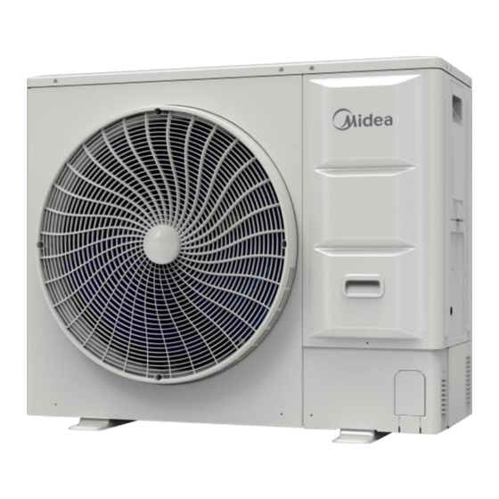
V8 Mini R410A VRF 50Hz 2 External Appearance 2.1 Indoor Units 2.1.1 Standard indoor units Table 1-2.1: Standard indoor unit appearance One-way Cassette Two-way Cassette Compact Four-way Cassette Four-way Cassette Arc Duct Medium Static Pressure Duct High Static Pressure Duct Floor Standing Wall-mounted Ceiling &... - Page 9 V8 Mini R410A VRF 50Hz 2.3 Outdoor Units Table 1-2.4: outdoor unit appearance 120/140/160 model...
-
Page 10: Nomenclature
○ ○ ○ ○ ○ 1 Legend Code Remarks Midea VRF indoor unit Function code H: HyperLink function Capacity index (the capacity in kW multiplied by 10) Indoor unit type Q1: One-way Cassette Q2: Two-way Cassette Q4C: Compact Four-way Cassette... - Page 11 ○ ○ ○ ○ ○ 1 Legend Code Remarks Midea VRF indoor unit Generation code 2: The 2nd generation 3: The 3rd generation Capacity index (the capacity in kW multiplied by 10) Indoor unit type Q1: One-way Cassette Q2: Two-way Cassette...
- Page 12 ○ ○ ○ 1 ⑨ Legend Code Remarks Midea VRF indoor unit The 2 generation VRF DC indoor unit Capacity index (the capacity in kW multiplied by 10) Indoor unit type FA: Fresh Air Processing Unit Series category (D: DC series)
-
Page 13: Combination Ratio
③ ④ ⑤ ⑥ ⑦ Legend Code Remarks Midea MV8M-120WV2RN1 The 8 generation VRF Mini VRF Capacity index (the capacity in kW multiplied by 10) Unit category (W: VRF outdoor unit) Type (V2: All DC inverter) Power supply G:380-415V, 3N~, 50/60Hz... - Page 14 V8 Mini R410A VRF 50Hz Table 1-5.2: Combinations of indoor and outdoor units Outdoor unit Sum of capacity indexes of Sum of capacity indexes of connected indoor Maximum number of capacity connected indoor units units (fresh air processing units and standard connected indoor Capacity model...
-
Page 15: Selection Procedure
V8 Mini R410A VRF 50Hz 5 Selection Procedure 5.1 Procedure Step 1: Establish design conditions Design temperature and humidity (indoor and outdoor) Required heat load of each room System peak load Piping length, level differences Indoor unit specifications (type and quantity) Step 2: Select indoor units Decide indoor unit safety factor Select indoor unit models ensuring that:... - Page 16 V8 Mini R410A VRF 50Hz 5.2 Example The following is a selection example based on total heat load for cooling. Figure 1-5.1: Room plan Room B Room C Room A Room D Step 1: Establish design conditions Indoor air temperature 25°C DB, 18°C WB; outdoor air temperature 33°C DB. ...
- Page 17 V8 Mini R410A VRF 50Hz Table 1-5.2: Extract from medium static pressure duct (T2) cooling capacity table Indoor air temperature Capacity 14°C WB 16°C WB 18°C WB 19°C WB 20°C WB 22°C WB 24°C WB Model index 20°C DB 23°C DB 26°C DB 27°C DB 28°C DB...
- Page 18 Using the outdoor unit’s cooling capacity table, interpolate to obtain the capacity (“B”) corrected for outdoor air temperature, indoor air temperature, and combination ratio. Refer to Tables 1-5.6 and 1-5.7. Table 1-5.6: Extract from Table 2-8.7 Table 1-5.7: Cooling capacity calculated by MV8M-120WV2RN1 cooling capacity interpolation Indoor air temp. Indoor air temp.
- Page 19 Calculate the corrected capacity of MV8M-120WV2RN1 (“C”) by using K1: C = B × K1 = 11.1 × 0.99= 10.99kW ...
- Page 20 V8 Mini R410A VRF 50Hz Part 2 Outdoor Unit Engineering Data 1 Specifications ................... 19 2 Dimensions ....................20 3 Installation Space Requirements .............. 21 4 Piping Diagrams ..................22 5 Wiring Diagrams ..................24 6 Electrical Characteristics ................26 7 Functional Components and Safety Devices ..........
-
Page 21: Specifications
V8 Mini R410A VRF 50Hz 1 Specifications 120/140/160 model Table 2-1.1: 120/140/160 model specifications Model MV8M-120WVR2N1 MV8M-140WV2RN1 MV8M-160WVR2N1 Model name Power supply 380-415V, 3N~, 50Hz 12.3 14.0 15.5 Capacity kBtu/h Cooling Power input 3.97 5.19 5.96 3.10 2.70 2.60 12.3 14.0 15.5 Capacity... -
Page 22: Dimensions
V8 Mini R410A VRF 50Hz 2 Dimensions 2.1 Single Units 120/140/160 model Unit:mm Model 120/140/160 1038 1073... -
Page 23: Installation Space Requirements
V8 Mini R410A VRF 50Hz 3 Installation Space Requirements Figure 2-3.1: Single unit installation (unit: mm) Single unit installation (Wall or obstacle) Air inlet surface > 300 Maintenance > 300 cable and pipeline surface Air inlet surface > 600 > 2000 Air outlet surface Figure 2-3.2: Multiple unit installation (unit: mm) Parallel connect the two units or above... -
Page 24: Piping Diagrams
V8 Mini R410A VRF 50Hz 4 Piping Diagrams 120/140/160 model Figure 2-4.1: 120/140/160 model piping diagram Legend Parts name Parts name Compressor Electronic expansion valve (EEVC) Oil separator Low pressure sensor High pressure switch Gas-liquid separator High pressure sensor Sensor Code Description Check value Main heat exchanger pipe temperature sensor... - Page 25 V8 Mini R410A VRF 50Hz Key components: 1. Oil separator: Separates oil from gas refrigerant pumped out of the compressor and quickly returns it to the compressor. Separation efficiency is up to 99%. 2. Gas-liquid separator: Separates liquid refrigerant from gas refrigerant, stores liquid refrigerant and oil to protect compressor from liquid hammering.
-
Page 26: Wiring Diagrams
V8 Mini R410A VRF 50Hz 5 Wiring Diagrams... - Page 27 V8 Mini R410A VRF 50Hz Legend Code Name Code Name COMP Compressor RA1/2/3 Reactor EEVA/C Electronic expansion valve Main heat exchanger pipe temperature sensor DC fan Outdoor ambient temperature sensor H-PRO High pressure switch Liquid pipe temperature sensor HEAT A Crankcase heater Plate heat exchanger outlet temperature sensor High pressure sensor...
-
Page 28: Electrical Characteristics
Min. Max. TOCA Power Volts (kW) volts volts 380-415 MV8M-120WV2RN1 10.4 380-415 MV8M-140WV2RN1 11.4 380-415 MV8M-160WV2RN1 12.9 Abbreviations: MCA: Minimum Circuit Amps; TOCA: Total Over-current Amps; MFA: Maximum Fuse Amps; MSC: Maximum Starting Current (A); RLA: Rated Load Amps; FLA: Fan... -
Page 29: Functional Components And Safety Devices
V8 Mini R410A VRF 50Hz 7 Functional Components and Safety Devices Table 2-7.1: 120/140/160 model functional components and safety devices Item Discharge pipe temperature sensors 90°C = 5kΩ ± 3% Compressor Crankcase heater 100°C Fan motor Safety thermostat 80°C High pressure switch Off: 4.3 (±0.1) MPa / On: 3.2 (±0.1) MPa System Heat exchanger temperature sensor... -
Page 30: Capacity Tables
V8 Mini R410A VRF 50Hz 8 Capacity Tables 8.1 Cooling Capacity Tables Table2-8.1:120 model cooling capacity Indoor air temp. (°C DB/WD) Outdoor air 22/15 23.3/16 25.8/18 27/19 28.2/20 30.7/22 32/24 temp. (°CDB) 11.1 12.3 14.8 16.0 17.2 19.7 20.8 11.1 12.3 14.8 16.0... - Page 31 V8 Mini R410A VRF 50Hz Table2-8.1:120 model cooling capacity(continued) Indoor air temp. (°C DB/WD) Outdoor air 22/15 23.3/16 25.8/18 27/19 28.2/20 30.7/22 32/24 temp. (°CDB) 10.4 12.5 13.5 14.6 16.7 18.7 10.4 12.5 13.5 14.6 16.7 18.7 10.4 12.5 13.5 14.6 16.7 18.7...
- Page 32 V8 Mini R410A VRF 50Hz Table2-8.1:120 model cooling capacity(continued) Indoor air temp. (°C DB/WD) Outdoor air 22/15 23.3/16 25.8/18 27/19 28.2/20 30.7/22 32/24 temp. (°CDB) 10.2 11.1 11.9 13.6 15.3 10.2 11.1 11.9 13.6 15.3 10.2 11.1 11.9 13.6 15.3 10.2 11.1 11.9...
- Page 33 V8 Mini R410A VRF 50Hz Table2-8.1:120 model cooling capacity(continued) Indoor air temp. (°C DB/WD) Outdoor air 22/15 23.3/16 25.8/18 27/19 28.2/20 30.7/22 32/24 temp. (°CDB) 10.6 11.9 10.6 11.9 10.6 11.9 10.6 11.9 10.6 11.9 10.6 11.9 10.6 11.9 10.6 11.9 10.6 11.9...
- Page 34 V8 Mini R410A VRF 50Hz Table2-8.1:120 model cooling capacity(continued) Indoor air temp. (°C DB/WD) Outdoor air 22/15 23.3/16 25.8/18 27/19 28.2/20 30.7/22 32/24 temp. (°CDB) Abbreviations: CR: Combination ratio TC: Total capacity (kW) PI: Power input (compressor + outdoor fan motor) (kW) Notes: Shaded cells indicate rating condition.
- Page 35 V8 Mini R410A VRF 50Hz Table2-8.2:140 model cooling capacity Indoor air temp. (°C DB/WD) Outdoor air 22/15 23.3/16 25.8/18 27/19 28.2/20 30.7/22 32/24 temp. (°CDB) 12.6 14.0 16.8 18.2 19.6 21.4 21.8 12.6 14.0 16.8 18.2 19.6 21.2 21.8 12.6 14.0 16.8 18.2...
- Page 36 V8 Mini R410A VRF 50Hz Table2-8.2:140 model cooling capacity(continued) Indoor air temp. (°C DB/WD) Outdoor air 22/15 23.3/16 25.8/18 27/19 28.2/20 30.7/22 32/24 temp. (°CDB) 10.7 11.8 14.2 15.4 16.6 19.0 20.7 10.7 11.8 14.2 15.4 16.6 19.0 20.6 10.7 11.8 14.2 15.4...
- Page 37 V8 Mini R410A VRF 50Hz Table2-8.2:140 model cooling capacity(continued) Indoor air temp. (°C DB/WD) Outdoor air 22/15 23.3/16 25.8/18 27/19 28.2/20 30.7/22 32/24 temp. (°CDB) 11.6 12.6 13.6 15.5 17.4 11.6 12.6 13.6 15.5 17.4 11.6 12.6 13.6 15.5 17.4 11.6 12.6 13.6...
- Page 38 V8 Mini R410A VRF 50Hz Table2-8.2:140 model cooling capacity(continued) Indoor air temp. (°C DB/WD) Outdoor air 22/15 23.3/16 25.8/18 27/19 28.2/20 30.7/22 32/24 temp. (°CDB) 10.6 12.1 13.6 10.6 12.1 13.6 10.6 12.1 13.6 10.6 12.1 13.6 10.6 12.1 13.6 10.6 12.1 13.6...
- Page 39 V8 Mini R410A VRF 50Hz Table2-8.2:140 model cooling capacity(continued) Indoor air temp. (°C DB/WD) Outdoor air 22/15 23.3/16 25.8/18 27/19 28.2/20 30.7/22 32/24 temp. (°CDB) Abbreviations: CR: Combination ratio TC: Total capacity (kW) PI: Power input (compressor + outdoor fan motor) (kW) Notes: Shaded cells indicate rating condition.
- Page 40 V8 Mini R410A VRF 50Hz Table2-8.3:160 model cooling capacity Indoor air temp. (°C DB/WD) Outdoor air 22/15 23.3/16 25.8/18 27/19 28.2/20 30.7/22 32/24 temp. (°CDB) 13.9 15.5 18.6 20.1 21.7 23.3 23.9 13.9 15.5 18.6 20.1 21.7 23.3 23.9 13.9 15.5 18.6 20.1...
- Page 41 V8 Mini R410A VRF 50Hz Table2-8.3:160 model cooling capacity(continued) Indoor air temp. (°C DB/WD) Outdoor air 22/15 23.3/16 25.8/18 27/19 28.2/20 30.7/22 32/24 temp. (°CDB) 11.8 13.1 15.7 17.0 18.4 21.0 22.5 11.8 13.1 15.7 17.0 18.4 21.0 22.4 11.8 13.1 15.7 17.0...
- Page 42 V8 Mini R410A VRF 50Hz Table2-8.3:160 model cooling capacity(continued) Indoor air temp. (°C DB/WD) Outdoor air 22/15 23.3/16 25.8/18 27/19 28.2/20 30.7/22 32/24 temp. (°CDB) 10.7 12.9 13.9 15.0 17.2 19.3 10.7 12.9 13.9 15.0 17.2 19.3 10.7 12.9 13.9 15.0 17.2 19.3...
- Page 43 V8 Mini R410A VRF 50Hz Table2-8.3:160 model cooling capacity(continued) Indoor air temp. (°C DB/WD) Outdoor air 22/15 23.3/16 25.8/18 27/19 28.2/20 30.7/22 32/24 temp. (°CDB) 10.0 10.9 11.7 13.4 15.0 10.0 10.9 11.7 13.4 15.0 10.0 10.9 11.7 13.4 15.0 10.0 10.9 11.7...
- Page 44 V8 Mini R410A VRF 50Hz Table2-8.3:160 model cooling capacity(continued) Indoor air temp. (°C DB/WD) Outdoor air 22/15 23.3/16 25.8/18 27/19 28.2/20 30.7/22 32/24 temp. (°CDB) 10.7 10.7 10.7 10.7 10.7 10.7 10.7 10.7 10.7 10.7 10.7 10.7 10.7 10.7 10.7 10.7 10.7 10.7...
- Page 45 V8 Mini R410A VRF 50Hz 8.2 Heating Capacity Tables Table2-8.4:120 model heating capacity Indoor air temp. °C DB Outdoor 16.0 18.0 20.0 21.0 22.0 24.0 air temp. °C DB °C WB -19.8 -20.0 10.2 10.1 10.1 10.1 10.0 10.0 -18.8 -19.0 10.6 10.5...
- Page 46 V8 Mini R410A VRF 50Hz Table2-8.4:120 model heating capacity (continued) Indoor air temp. °C DB Outdoor 16.0 18.0 20.0 21.0 22.0 24.0 air temp. °C DB °C WB -19.8 -20.0 10.0 10.0 10.0 -18.8 -19.0 10.3 10.3 10.2 10.2 10.2 10.3 -16.7 -17.0...
- Page 47 V8 Mini R410A VRF 50Hz Table2-8.4:120 model heating capacity (continued) Indoor air temp. °C DB Outdoor 16.0 18.0 20.0 21.0 22.0 24.0 air temp. °C DB °C WB -19.8 -20.0 -18.8 -19.0 10.1 10.2 -16.7 -17.0 10.8 10.6 -13.7 -15.0 11.3 10.6 -11.8...
- Page 48 V8 Mini R410A VRF 50Hz Table2-8.5:140 model heating capacity Indoor air temp. °C DB Outdoor 16.0 18.0 20.0 21.0 22.0 24.0 air temp. °C DB °C WB -19.8 -20.0 10.6 10.5 10.4 10.3 10.3 10.3 -18.8 -19.0 10.9 10.8 10.7 10.7 10.6 10.6...
- Page 49 V8 Mini R410A VRF 50Hz Table2-8.5:140 model heating capacity (continued) Indoor air temp. °C DB Outdoor 16.0 18.0 20.0 21.0 22.0 24.0 air temp. °C DB °C WB -19.8 -20.0 10.3 10.2 10.2 10.1 10.1 10.1 -18.8 -19.0 10.6 10.5 10.5 10.5 10.5...
- Page 50 V8 Mini R410A VRF 50Hz Table2-8.5:140 model heating capacity (continued) Indoor air temp. °C DB Outdoor 16.0 18.0 20.0 21.0 22.0 24.0 air temp. °C DB °C WB -19.8 -20.0 10.0 10.0 10.0 10.0 10.1 -18.8 -19.0 10.3 10.3 10.3 10.3 10.3 -16.7...
- Page 51 V8 Mini R410A VRF 50Hz Table2-8.6:160 model heating capacity Indoor air temp. °C DB Outdoor 16.0 18.0 20.0 21.0 22.0 24.0 air temp. °C DB °C WB -19.8 -20.0 11.2 11.1 11.0 10.9 10.8 10.8 -18.8 -19.0 11.6 11.4 11.3 11.3 11.2 11.1...
- Page 52 V8 Mini R410A VRF 50Hz Table2-8.6:160 model heating capacity (continued) Indoor air temp. °C DB Outdoor 16.0 18.0 20.0 21.0 22.0 24.0 air temp. °C DB °C WB -19.8 -20.0 10.8 10.7 10.6 10.6 10.6 10.5 -18.8 -19.0 11.2 11.1 11.0 10.9 10.9...
- Page 53 V8 Mini R410A VRF 50Hz Table2-8.6:160 model heating capacity (continued) Indoor air temp. °C DB Outdoor 16.0 18.0 20.0 21.0 22.0 24.0 air temp. °C DB °C WB -19.8 -20.0 10.4 10.4 10.3 10.3 10.3 10.4 -18.8 -19.0 10.8 10.7 10.6 10.6 10.6...
- Page 54 V8 Mini R410A VRF 50Hz 8.3 Capacity Correction Factors for Piping Length and Level Difference Figure 2-8.1: 120 model rate of change in cooling capacity Figure 2-8.2: 120 model rate of change in heating capacity 100 110 120 Figure 2-8.3: 140 model rate of change in cooling capacity Figure 2-8.4: 140 model rate of change in heating capacity 100 110 120 Figure 2-8.5: 160 model rate of change in cooling capacity...
- Page 55 V8 Mini R410A VRF 50Hz 8.4 Capacity Correction Factors for Frost Accumulation The heating capacity tables do not take account of the reduction in capacity when frost has accumulated or while the defrosting operation is in progress. If snow has accumulated against the outside surface of the outdoor unit heat exchanger heating capacity is reduced.
-
Page 56: Operating Limits
V8 Mini R410A VRF 50Hz 9 Operating Limits Figure 2-9.1: Operating limits ℃ Note1:Outdoor operating temperature under -5 in "cooling" mode, the startup capacity of IDUs must meet at least 30% of ODU capacity. Table 2-9.1: Operating limits Mode Outdoor temperature/DB Room temperature/WB Cooling operation -15℃~52℃... -
Page 57: Sound Levels
V8 Mini R410A VRF 50Hz 10 Sound Levels 10.1 Overall Table 2-10.1: Sound pressure level Model dB(A) Height (m) MV8M-80WV2N1 MV8M-100WV2N1 MV8M-120WV2N1 MV8M-140WV2N1 MV8M-160WV2N1 Notes: Sound pressure level is measured at a position 1m in front of the unit and Hm above the floor in a semi-anechoic chamber. During in-situ operation, sound pressure levels may be higher as a result of ambient noise. - Page 58 V8 Mini R410A VRF 50Hz 10.2 Octave Band Levels Figure 2-10.2: 120 model octave band level Figure 2-10.3: 140 model octave band level NC-70 NC-70 NC-60 NC-60 NC-50 NC-50 NC-40 NC-40 NC-30 NC-30 NC-20 NC-20 125 250 500 1000 2000 4000 8000 125 250 500 1000 2000 4000 8000 Octave band center frequency (Hz) Octave band center frequency (Hz)
-
Page 59: Accessories
V8 Mini R410A VRF 50Hz 11 Accessories 11.1 Standard Accessories Table 2-11.1: Standard accessories Name Shape Quantity Function Owner’s and installation manual Water outlet connection pipe Build-out resistor Enhances communication stability Magnetic ring Improve communication reliability 11.2 Optional Accessories Table 2-11.3: Optional accessories Net/gross weight Optional accessories Model... - Page 60 V8 Mini R410A VRF 50Hz Part 3 System Design and Installation 1 Preface to Part 3 ..................59 2 Unit Placement and Installation ............... 60 3 Refrigerant Piping Design ................. 64 4 Refrigerant Piping Installation ..............70 5 Drain Piping ..................... 82 6 Insulation ....................
-
Page 61: Preface To Part 3
V8 Mini R410A VRF 50Hz 1 Preface to Part 3 1.1 Notes for Installers Boxes The information contained in this Engineering Data Book may primarily be of use during the system design stage of a Mini Series VRF project. Additional important information which may primarily be of use during field installation has been placed in boxes, such as the example below, titled “Notes for installers”. -
Page 62: Unit Placement And Installation
V8 Mini R410A VRF 50Hz 2 Unit Placement and Installation 2.1 Outdoor Units 2.1.1 Placement considerations Placement of outdoor units should take account of the following considerations: Air conditioners should not be exposed to direct radiation from a high-temperature heat source. ... - Page 63 V8 Mini R410A VRF 50Hz 2.1.3 Base structures Outdoor unit base structure design should take account of the following considerations: A solid base prevents excess vibration and noise. Outdoor unit bases should be constructed on solid ground or on structures of sufficient strength to support the units’...
- Page 64 V8 Mini R410A VRF 50Hz 2.1.4 Acceptance and unpacking Notes for installers When units are delivered check whether any damage occurred during shipment. If there is damage to the surface or outside of a unit, submit a written report to the shipping company. ...
- Page 65 V8 Mini R410A VRF 50Hz 2.2 Indoor Units 2.2.1 Placement considerations Placement of indoor units should take account of the following considerations: Sufficient space for drain piping and for access during servicing and maintenance should be allowed. To ensure a good cooling/heating effect, short-circuit ventilation (where outlet air returns quickly to a unit’s air inlet) should be avoided.
-
Page 66: Refrigerant Piping Design
V8 Mini R410A VRF 50Hz 3 Refrigerant Piping Design 3.1 Design Considerations Refrigerant piping design should take account of the following considerations: The amount of brazing required should be kept to a minimum. On the two inside sides of the first indoor branch joint (“A” in Figures 3-3.1 and Figure 3-3.3) the system should, as far as possible, be equal in terms of number of units, total capacities and total piping lengths. - Page 67 Table 3-3.3: Connectable indoor units Maximum number of Connectable indoor unit capacity range Connectable indoor unit capacity range Outdoor unit model connected indoor units 50%~160% 50%~130% MV8M-120WV2RN1 61.5 to 196.8 61.5 to 159.9 MV8M-140WV2RN1 70 to 224 70 to 182 MV8M-160WV2RN1 77.5 to 248 77.5 to 201.5...
- Page 68 V8 Mini R410A VRF 50Hz 3.4 Selecting Piping Diameters Tables 3-3.4 to 3-3.7 below, specify the required pipe diameters for the indoor and outdoor piping. The main pipe (L1) and first indoor branch joint (A) should be sized according to whichever of Tables 3-3.4 and 3-3.5 indicates the larger size. Figure 3-3.3: Selecting piping diameters Maximum equivalent piping length from the outdoor unit to the farthest indoor unit is ≤...
- Page 69 V8 Mini R410A VRF 50Hz 3.5 Refrigerant Piping Selection Example The example below illustrates the piping selection procedure for a system consisting of an outdoor unit (160 model) and 6 indoor units (2.2 kW×1+2.8 kW×5), as shown in Figure 3-3.4. The system's total equivalent length of all liquid and gas pipes is less than 90m.
- Page 70 V8 Mini R410A VRF 50Hz 3.6 Branch Joints Branch joint design should take account of the following: U-shaped branch joints should be used – tee joints are not suitable. Branch joint dimensions are given in Tables 3-3.8. To ensure even distribution of refrigerant, branch joints should not be installed within 500mm of a 90° bend, another branch joint or the straight section of piping leading to an indoor unit, with the minimum 500mm being measured from the point where the branch joint is connected to the piping, as shown in Figure 3-3.5.
- Page 71 V8 Mini R410A VRF 50Hz 3.7 Refrigerant Leakage Precautions R410A refrigerant is not flammable in air at temperatures up to 100°C at atmospheric pressure and is generally considered a safe substance to use in air conditioning systems. Nevertheless, precautions should be taken to avoid danger to life in the unlikely event of a major refrigerant leakage.
-
Page 72: Refrigerant Piping Installation
V8 Mini R410A VRF 50Hz 4 Refrigerant Piping Installation 4.1 Procedure and Principles 4.1.1 Installation procedure Notes for installers Installation of the refrigerant piping system should proceed in the following order: Pipe Pipe brazing Pipe Gastightness Joint Vacuum drying insulation and installation flushing... - Page 73 V8 Mini R410A VRF 50Hz 4.2 Storing Copper Piping 4.2.1 Pipe delivery, storage and sealing Notes for installers Ensure that piping does not get bent or deformed during delivery or whilst stored. On construction sites store piping in a designated location. ...
- Page 74 V8 Mini R410A VRF 50Hz 4.3.3 Expanding copper piping ends Notes for installers Ends of copper piping can be expanded so that another length of piping can be inserted and the joint brazed. Insert the expanding head of the pipe expander into the pipe. After completing pipe expansion, rotate the copper pipe a few degrees to rectify the straight line mark left by the expanding head.
- Page 75 V8 Mini R410A VRF 50Hz 4.3.5 Bending piping Bending copper piping reduces the number of brazed joints required and can improve quality and save material. Notes for installers Piping bending methods Hand bending is suitable for thin copper piping (Ф6. 35mm - Ф12. 7mm). ...
- Page 76 V8 Mini R410A VRF 50Hz 4.5 Brazing Care must be taken to prevent oxide forming on the inside of copper piping during brazing. The presence of oxide in a refrigerant system adversely affects the operation of valves and compressors, potentially leading to low efficiency or even compressor failure.
- Page 77 V8 Mini R410A VRF 50Hz … box continued from previous page Piping orientation during brazing Brazing should be conducted downwards or horizontally to avoid filler leakage. Figure 3-4.6: Piping orientation during brazing Piping overlap during brazing Table 3-4.3 specifies the minimum permissible piping overlap and the range of permissible gap sizes for brazed joints on piping of different diameters.
- Page 78 V8 Mini R410A VRF 50Hz 4.6 Branch Joints Notes for installers Use U-shaped branch joints as specified on the Figure 3-4.8: Branch joint orientation construction drawings – do not replace U-shaped branch joints with tee joints. Indoor branch joints may be installed either horizontally or vertically.
- Page 79 V8 Mini R410A VRF 50Hz 4.7 Direction of refrigerant pipe connection Field piping can be connected in 4 directions. Before connecting, knock off the plate in the corresponding direction. Figure 3-4.9: Direction of refrigerant pipe connection Back out pipe Side out pipe Front out Bottom out...
- Page 80 V8 Mini R410A VRF 50Hz 4.8.2 Procedure Notes for installers Warning Only use nitrogen for flushing. Using carbon dioxide risks leaving condensation in the piping. Oxygen, air, refrigerant, flammable gases and toxic gases must not be used for flushing. Use of such gases may result in fire or explosion. Procedure The liquid and gas sides can be flushed simultaneously;...
- Page 81 V8 Mini R410A VRF 50Hz 4.9 Gastightness Test 4.9.1 Purpose To prevent faults caused by refrigerant leakage, a gastightness test should be performed before system commissioning. 4.9.2 Procedure Notes for installers Warning Only dry nitrogen should be used for gastightness testing. Oxygen, air, flammable gases and toxic gases must not be used for gastightness testing.
- Page 82 V8 Mini R410A VRF 50Hz 4.9.3 Leak detection Notes for installers The general methods for identifying the source of a leak are as follows: 1. Audio detection: relatively large leaks are audible. 2. Touch detection: place your hand at joints to feel for escaping gas. 3.
- Page 83 V8 Mini R410A VRF 50Hz 4.10.2 Procedure Notes for installers During vacuum drying, a vacuum pump is used to lower the pressure in the piping to the extent that any moisture present evaporates. At 5mmHg (755mmHg below typical atmospheric pressure) the boiling point of water is 0°C. Therefore a vacuum pump capable of maintaining a pressure of -756mmHg or lower should be used.
-
Page 84: Drain Piping
V8 Mini R410A VRF 50Hz 5 Drain Piping 5.1 Design Considerations Drain piping design should take account of the following considerations: Indoor unit condensate drain piping needs to be of sufficient diameter to carry the volume of condensate produced at the indoor units and installed at a slope sufficient to allow drainage. - Page 85 V8 Mini R410A VRF 50Hz Figure 3-5.5: Drain piping air vents Vent Air conditioner drain piping should be installed separately from waste, rainwater and other drain piping and should not come into direct contact with the ground. Drain piping diameter should be not less than the indoor units’ drain piping connection. ...
- Page 86 V8 Mini R410A VRF 50Hz Table 3-5.2: Vertical drain piping diameters Nominal PVC piping Capacity (L/h) Remarks diameter (mm) PVC25 Branch piping only PVC32 PVC40 PVC50 1440 PVC63 2760 Branch or main piping PVC75 5710 PVC90 8280 5.4 Drain Piping for Units with Lift Pumps Drain piping for units with lift pumps should take account of the following additional considerations: ...
- Page 87 V8 Mini R410A VRF 50Hz 5.6 Watertightness Test and Water Flow Test Once installation of a drainage piping system is complete, watertightness and water flow tests should be performed. Notes for installers Watertightness test Fill the piping with water and test for leakages over a 24-hour period. Water flow test (natural drainage test) ...
-
Page 88: Insulation
V8 Mini R410A VRF 50Hz 6 Insulation 6.1 Refrigerant Piping Insulation 6.1.1 Purpose During operation, the temperature of the refrigerant piping varies. Insulation is required to ensure unit performance and compressor lifespan. During cooling, the gas pipe temperature can be very low. Insulation prevents condensation forming on the piping. - Page 89 V8 Mini R410A VRF 50Hz 6.1.5 Installation of joint insulation Insulation at joints in the refrigerant piping should be installed after the gastightness test has been successfully completed. The procedure at each joint is as follows: 1. Cut a section of insulation 50 to 100mm longer than the gap to be filled. Ensure that the cross-sectional and longitudinal openings are all cut evenly.
-
Page 90: Charging Refrigerant
V8 Mini R410A VRF 50Hz 7 Charging Refrigerant 7.1 Calculating Additional Refrigerant Charge Calculate the additional charge amount of total refrigerant R(kg) according to the following formula: R (kg) = R1 – 0.1 × N R1 is the additional refrigerant charge quantity for liquid piping N is the number of Arc Duct indoor units whose height is 199mm. - Page 91 V8 Mini R410A VRF 50Hz 7.2 Adding Refrigerant Notes for installers Caution Only charge refrigerant after performing a gastightness test and vacuum drying. Never charge more refrigerant than required as doing so can lead to liquid hammering. ...
-
Page 92: Electrical Wiring
V8 Mini R410A VRF 50Hz 8 Electrical Wiring 8.1 General Notes for installers Caution All installation and wiring must be carried out by competent and suitably qualified, certified and accredited professionals and in accordance with all applicable legislation. ... - Page 93 V8 Mini R410A VRF 50Hz Figure 3-8.1: Indoor unit unified power supply wiring Single-phase 220~ 50/60Hz Leakage protector Manual switch Branch box Indoor unit Notes for installers The 380-415V, 3N~, 50Hz power supply should be connected to the outdoor unit power supply terminals as shown in Figure 3-8.2.
- Page 94 V8 Mini R410A VRF 50Hz Table 3-8.1: Communication connection between ODU and IDUs Communication connection Wire diameter Indoor unit generation Length limitation (m) type All V8 indoor units and unified power M1 M2 / P Q 2х0.75 2000 / 1200 supply All V8 indoor units and separate power M1 M2...
- Page 95 V8 Mini R410A VRF 50Hz 8.3.2 Outdoor unit and indoor units’ P Q E communication Communication wiring design and installation should adhere to the following requirements: 0.75mm three-core shielded cable should be used for communication wiring. Using other types of cable can lead to interference and malfunction.
- Page 96 V8 Mini R410A VRF 50Hz 8.3.3 Outdoor unit and indoor units’ P Q communication Communication wiring design and installation should adhere to the following requirements: 0.75mm2 two-core shielded cable should be used for communication wiring. Using other types of cable can lead to interference and malfunction.
- Page 97 V8 Mini R410A VRF 50Hz 8.3.4 Outdoor unit and indoor units’ M1, M2 communication-IDUs uniform power supplied Communication wiring design and installation should adhere to the following requirements when all IDUs uniform power supplied: 0.75mm two-core cable should be used for communication wiring when all the indoor units are uniform power supplied.
- Page 98 V8 Mini R410A VRF 50Hz Figure 3-8.8: M1 M2 communication wiring configuration – IDUs separate power supplied L1+La+Lx≤200m, L11≤200mm. Communication wiring 2*1.5mm Communication wire Power wire Repeater 1 Breaker breaker T O D O W N ID U · · · (2-9)# IDU T O U P ID U 1# IDU...
-
Page 99: Installation In Areas Of High Salinity
V8 Mini R410A VRF 50Hz 9 Installation in Areas of High Salinity 9.1 Caution Do not install outdoor units where they could be directly exposed to sea air. Corrosion, particularly on the condenser and evaporator fins, could cause product malfunction or inefficient performance. Outdoor units installed in seaside locations should be placed such as to avoid direct exposure to the sea air and additional anticorrosion treatment options should be selected, otherwise the service life of the outdoor units will be seriously affected. -
Page 100: Commissioning
V8 Mini R410A VRF 50Hz 10 Commissioning 10.1 Pre-commissioning Checks Before turning on the power to the indoor and outdoor units, ensure the following: Installation Check if the unit is installed correctly to prevent strange noises and vibrations when the unit starts. ... - Page 101 V8 Mini R410A VRF 50Hz 10.2 Outdoor Unit Address and Communication Type Setting Step 1: Power on Cover the lower panel of the ODU, and power on all IDUs and ODUs. Step 2: Enter commissioning mode When the ODU is first powered on, it displays "-. -. -. -.", which means the unit is not commissioned. Long press the “DOWN” and “UP”...
- Page 102 V8 Mini R410A VRF 50Hz Figure 3-10.1: Test Run Procedure The system is powered on and display “-.-.-.-.” Long press the “DOWN” and “UP” buttons simultaneously for 5s on the ODU to enter the commissioning Set the number of The 3rd and 4th digits represent the IDUs, displays "01 01"...
- Page 103 V8 Mini R410A VRF 50Hz 10.3 Multi-system Projects For projects with multiple refrigerant systems, each independent refrigeration system (i.e. each system of one outdoor unit and its connected indoor units) should be given a test run independently, before the multiple systems that make up a project are run simultaneously.
-
Page 104: Appendix To Part 3 - System Commissioning Report
V8 Mini R410A VRF 50Hz 11 Appendix to Part 3 – System Commissioning Report A total of up to 11 report sheets should be completed for each system: One Sheet A, one Sheet B and one Sheet C per system. ... - Page 105 V8 Mini R410A VRF 50Hz System Commissioning Report – Sheet A SYSTEM INFORMATION Project name and location Customer company System name Installation company Commissioning date Agent company Commissioning Outdoor ambient temp. engineer Model Serial no. Power supply (V) Outdoor unit information OUTDOOR UNIT Compressor suction pipe Current (A)
- Page 106 V8 Mini R410A VRF 50Hz System Commissioning Report – Sheet B SYSTEM INFORMATION Project name and location Customer company System name Installation company Commissioning date Agent company Commissioning Outdoor ambient temp. engineer Model Serial no. Power supply (V) Outdoor unit information OUTDOOR UNIT Compressor suction pipe Current (A)
- Page 107 RECORD OF ISSUES SEEN DURING COMMISSIONING Serial no. of Description of observed issue Suspected cause Troubleshooting undertaken relevant unit OUTDOOR UNIT FINAL CHECKLIST SW2 system check performed? Any abnormal noise? Any abnormal vibration? Fan rotation normal? Commissioning engineer Dealer Midea representative Name: Signature: Date:...
- Page 108 V8 Mini R410A VRF 50Hz System Commissioning Report – Sheet D Project name and location System name Observed values DSP1 Cooling Heating Parameters displayed on DSP2 Remarks content mode mode --.-- "Standby (ODU address+ IDU number)/frequency/special status" 0.-- Outdoor unit address V8 Mini series outdoor unit: 0 1.-- Outdoor unit capacity (HP)
- Page 109 V8 Mini R410A VRF 50Hz System Commissioning Report – Sheet D Project name and location System name … table continued from previous page Observed values DSP1 Cooling Heating Parameters displayed on DSP2 Remarks content mode mode 34.-- Reserved 35.-- Compressor discharge pressure (MPa) Actual value = value displayed ×...
- Page 110 V8 Mini R410A VRF 50Hz...
- Page 111 Ver. 2023-01 Midea Building Technologies Division Midea Group Add.: Midea Headquarters Building, 6 Midea Avenue, Shunde, Foshan, Guangdong, China Postal code: 528311 mbt.midea.com / global.midea.com/tsp.midea.com Note: Product specifications change from time to time as product improvements and developments are released and may vary from those in this...
Need help?
Do you have a question about the MV8M-120WV2RN1 and is the answer not in the manual?
Questions and answers