
Related Manuals for Midea V5 X VRF Series


Summary of Contents for Midea V5 X VRF Series
- Page 1 Technical Service Manual V5 X Series VRF Model: 3 phase, 380-415V, 50Hz MV5-X224W/V2GN1-AU MV5-X280W/V2GN1-AU MV5-X335W/V2GN1-AU MV5-X400W/V2GN1-AU MV5-X450W/V2GN1-AU MV5-X500W/V2GN1-AU...
- Page 2 Contents 001 Part 1 General Information 013 Part 2 Selection Procedure 019 Part 3 Specifications & Performances 082 Part 4 Installation 129 Part 5 Troubleshooting...
- Page 3 MCAC-VTSM-2015-10 R410A All DC Inverter V5 X Series 50Hz Part 1 General Information 1. Features ......................2 2. Outdoor units ....................7 3. Indoor units lineup ..................11 4. Nomenclature ....................12 General Information...
- Page 4 R410A All DC Inverter V5 X Series 50Hz MCAC-VTSM-2015-10 1. Features 1.1 Energy saving V5 X Series achieves the industry's top class energy efficiency in cooling and heating by utilizing all DC inverter compressors, all DC fan motors, and high efficiency heat exchanger. 1.1.1 High EER and COP values The cooling EER is up to 4.7 and the heating COP is up to 5.6 in the 8HP category.
- Page 5 MCAC-VTSM-2015-10 R410A All DC Inverter V5 X Series 50Hz 1.1.4 High efficiency heat exchanger Newly designed window type fins enlarge the heat exchange area and decrease air resistance, enhance heat exchange performance and save more energy. Hydrophilic fins and internally threaded copper pipes optimize heat exchange efficiency. ...
- Page 6 R410A All DC Inverter V5 X Series 50Hz MCAC-VTSM-2015-10 1.2.3 Flexible piping design Total piping length 1000m Longest length actual (Equivalent) 175(200)m Longest length after first branch 90*m Level difference between indoor 90(110)m and outdoor units - ODU up (down) Level difference between indoor units *The longest piping length is 40m standard.
- Page 7 MCAC-VTSM-2015-10 R410A All DC Inverter V5 X Series 50Hz 1.3.3 Precise oil control technology 5 stages oil control technology ensures all outdoor unit and compressor oil is always kept at a safe level, completely solving any compressor oil shortage problems. ...
- Page 8 R410A All DC Inverter V5 X Series 50Hz MCAC-VTSM-2015-10 1.5 Easy installation and service 1.5.1 Auto addressing Outdoor unit can distribute addresses for indoor units automatically. Wireless and wired controllers can query and modify each indoor unit's address. 1.5.2 Simple communication wiring Centralized controller (CCM03 or CCM30) can be connected from indoor side or outdoor side (XYE terminals) at will.
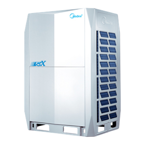
- Page 9 MCAC-VTSM-2015-10 R410A All DC Inverter V5 X Series 50Hz 2. Outdoor units Outdoor units lineup The outdoor units capacity ranges from 8HP up to 88HP in 2HP increments, a max. combination of 4 basic models. 8,10,12HP 14,16,18HP 20~36HP 38~54HP 56~72HP General Information...
- Page 10 R410A All DC Inverter V5 X Series 50Hz MCAC-VTSM-2015-10 Standard combination Cooling Heating Max. quantity of Capacity Combination type capacity capacity connectable indoor units 22.4 10HP 31.5 12HP 33.5 37.5 14HP 16HP 8+10HP 50.4 56.5 10+10HP 8+14HP 62.4 10+14HP 76.5 12+14HP 73.5...
- Page 11 MCAC-VTSM-2015-10 R410A All DC Inverter V5 X Series 50Hz Space saving combination Cooling capacity Heating capacity Max. quantity of Capacity Combination type connectable indoor units 22.4 10HP 31.5 12HP 33.5 37.5 14HP 16HP 18HP 8+12HP 55.9 62.5 10+12HP 61.5 12+12HP 8+18HP 72.4...
- Page 12 R410A All DC Inverter V5 X Series 50Hz MCAC-VTSM-2015-10 Energy efficiency combination Max. quantity of Cooling capacity Heating capacity Capacity Combination type connectable indoor units 22.4 10HP 31.5 12HP 33.5 37.5 14HP 8+8HP 44.8 8+10HP 50.4 56.5 10+10HP 8+14HP 62.4 8+8+8HP 67.2...
- Page 13 MCAC-VTSM-2015-10 R410A All DC Inverter V5 X Series 50Hz 3. Indoor units lineup Type Capacity Compact Low static Concealed One-way Two-way Four-way (kW) four-way pressure duct unit cassette Cassette cassette cassette duct (A5 Type) 11.2 11.2 11.2 12.5 Type Capacity High static Fresh air Ceiling &...
- Page 14 M V5 – X 224 W / V2 G N1 - AU Designed for Australia Refrigerant type N1: R410A Power supply G: 380-415V, 3Ph, 50Hz/60Hz Type V2: All DC Inverter type Outdoor Unit Cooling Capacity (×100W) X Series The 5th generation inverter VRF unit Midea General Information...
- Page 15 MCAC-VTSM-2015-10 R410A All DC Inverter V5 X Series 50Hz Part 2 Selection Procedure 1. Introduction ....................14 2. Unit selection (based on cooling load) ............17 Selection Procedure...
- Page 16 R410A All DC Inverter V5 X Series 50Hz MCAC-VTSM-2015-10 1. Introduction 1.1 Model selection procedure Select the model and calculate the capacity for each refrigerant system according to the procedure shown below. -conditioning load, Calculate the maximum air-conditioning load for each room or zone.
- Page 17 MCAC-VTSM-2015-10 R410A All DC Inverter V5 X Series 50Hz of the rooms. The indoor and outdoor unit combination is determined that the sum of indoor unit capacity index is nearest to and smaller than the capacity index at 100% combination ratio of each outdoor unit. Up to 13~36 indoor units can be connected to one outdoor unit.
- Page 18 R410A All DC Inverter V5 X Series 50Hz MCAC-VTSM-2015-10 INDOOR UNIT CAPACITY INDEX Model Model Model Model Model Model Model Model Model Model Unit Size Capacity 11.2 Model Model Model Model Model Model Model Model Model Unit Size Capacity 12.5 1.4 Actual performance data Use OUTDOOR UNIT CAPACITY TABLES.
- Page 19 MCAC-VTSM-2015-10 R410A All DC Inverter V5 X Series 50Hz data means outdoor unit is lower. 1.5.2 Heating capacity modification H(m) -100 -110 180 190 200 210 220 90 100 110 120 130 140 150 160 170 L(m) 2. Unit selection (based on cooling load) 2.1 Given condition Condition: Cooling: indoor temperature 20...
- Page 20 R410A All DC Inverter V5 X Series 50Hz MCAC-VTSM-2015-10 Then calculate the outdoor capacity in 92% combination index: 26.8+{(28.3-26.8)/10}×2=27.1kW; Capacity modification coefficient with pipe length 50m(164ft) and height difference 30m: 0.958 Each indoor unit cooling capacity Room A: MDV-D22T2 (27.1×22/258×0.958=2.21kW) Room B: MDV-D28T2 (27.1×28/258×0.958=2.82kW) Room C: MDV-D36T2 (27.1×36/258×0.958=3.62kW) Room D: MDV-D45T2 (27.1×45/258×0.958=4.53kW)
- Page 21 MCAC-VTSM-2015-10 R410A All DC Inverter V5 X Series 50Hz Part 3 Specifications & Performances 1. Specifications ....................20 2. Dimensions ....................22 3. Service space ....................26 4. Piping diagrams ................... 27 5. Wiring diagram and field wiring ..............29 6.
- Page 22 R410A All DC Inverter V5 X Series 50Hz MCAC-VTSM-2015-10 1. Specifications Outdoor unit specifications Model MV5-X224W/V2GN1-AU MV5-X280W/V2GN1-AU MV5-X335W/V2GN1-AU Power supply V/Ph/Hz 380-415/3/50 Capacity 22.4 28.0 33.5 Cooling Power input 5.51 7.20 9.00 4.07 3.89 3.72 Capacity 25.0 31.5 37.5 Heating Power input 5.78 8.27...
- Page 23 MCAC-VTSM-2015-10 R410A All DC Inverter V5 X Series 50Hz Type R410A Refrigerant Factory charging Φ12.7 Φ12.7 Φ15.9 Liquid pipe Pipe Φ22.2 Φ22.2 Φ28.6 Gas pipe connections Φ8 Oil balance pipe Design pressure(High/low) 4.4/2.6 Air flow rate 12000 Sound pressure level dB(A) Net dimension (W×H×D) 990×1635×790...
- Page 24 R410A All DC Inverter V5 X Series 50Hz MCAC-VTSM-2015-10 Outdoor unit specifications Model MV5-X400W/V2GN1-AU MV5-X450W/V2GN1-AU MV5-X500W/V2GN1-AU Power supply V/Ph/Hz 380-415/3/50 Capacity 40.0 45.0 50.0 Cooling Power input 10.80 12.80 14.50 3.70 3.52 3.45 Capacity 45.0 50.0 56.0 Heating Power input 11.58 13.35 16.67...
- Page 25 MCAC-VTSM-2015-10 R410A All DC Inverter V5 X Series 50Hz Type R410A Refrigerant Factory charging Φ15.9 Φ15.9 Φ19.1 Liquid pipe Pipe Φ25.4 Φ25.4 Φ31.8 Gas pipe connections Φ8 Oil balance pipe Design pressure(High/low) 4.4/2.6 Air flow rate 14000 14000 16000 Sound pressure level dB(A) Net dimension (W×H×D) 1340×1635×790...
- Page 26 R410A All DC Inverter V5 X Series 50Hz MCAC-VTSM-2015-10 2. Dimensions 2.1 Overall dimensions 8, 10, 12HP, unit: mm 14, 16, 18HP, unit: mm 1340 Specifications & Performances...
- Page 27 MCAC-VTSM-2015-10 R410A All DC Inverter V5 X Series 50Hz 2.2 Section dimensions Gauge point Detect the pressure/ Refrigerant replenishment/vacuumize Liquid side (Piping diameter is ΦA) Oil balance pipe (For combined outdoor units, the connection piping diameter is Φ5/16in.(Φ8mm)) Gas side (Piping diameter isΦB) 50(2) 63(2-1/2)
- Page 28 R410A All DC Inverter V5 X Series 50Hz MCAC-VTSM-2015-10 3. Service space Ensure enough space for maintenance. Combined modules must be level. When installing the unit, leave enough space for maintenance. Unit: mm (in.) (Air-out ) >1000mm 100m m ~500m m 100m m ~500m m (Air-in ) (Air-in )
- Page 29 MCAC-VTSM-2015-10 R410A All DC Inverter V5 X Series 50Hz outdoor unit to facilitate heat dissipation. See the figure below. The height of the air director is HD (namely H-h). Please make the air director on site. >1m Front Front 100-500mm ...
- Page 30 R410A All DC Inverter V5 X Series 50Hz MCAC-VTSM-2015-10 14, 16, 18HP Key components: Oil separator: It is used to separate oil from high pressure and high temperature gas refrigerant, which is pumped out from compressor. The separation efficiency is up to 99%, it makes the oil return back to each compressor very soon.
- Page 31 R410A All DC Inverter V5 X Series 50Hz MCAC-VTSM-2015-10 5. Wiring diagram and field wiring 5.1 Wiring diagram 8, 10, 12HP Specifications & Performances...
- Page 32 R410A All DC Inverter V5 X Series 50Hz MCAC-VTSM-2015-10 Wiring diagram 14, 16, 18HP Specifications & Performances...
- Page 33 MCAC-VTSM-2015-10 R410A All DC Inverter V5 X Series 50Hz 5.2 Field wiring 5.2.1 Signal wire between outdoor unit and indoor unit Signal wire of indoor/outdoor unit adopts 3-core shielded wire (≥0.75mm ) which has polarity, please connect it correctly. Master unit Slave unit Slave unit Slave unit (P Q E ) (H 1 H 2 E ) (H 1 H 2 E ) (H 1 H 2 E )
- Page 34 R410A All DC Inverter V5 X Series 50Hz MCAC-VTSM-2015-10 6. Electric characteristics Units Power supply Compressor Model Voltage Min. Max. TOCA 20.0 25.6 0.48 10HP 21.0 25.6 0.48 12HP 23.0 27.6 0.48 380~415 14HP 27.3 37.4 7.2×2 0.4+0.28 3.9+3.5 16HP 29.9 37.5 7.3×2...
- Page 35 MCAC-VTSM-2015-10 R410A All DC Inverter V5 X Series 50Hz 7. Capacity tables 7.1 Cooling capacity tables CR: Combination Ratio; TC: Total Capacity (kW); PI: Power Input (kW) (Compressor + Outdoor fan motor) Indoor temperature(°C DB/WD) Outdoor DB:20.8,WB:14 DB:23.3,WB:16 DB:25.8,WB:18 DB:27,WB:19 DB:28.2,WB:20 DB:30.7,WB:22 DB:32,WB:24...
- Page 36 R410A All DC Inverter V5 X Series 50Hz MCAC-VTSM-2015-10 Cooling capacity tables CR: Combination Ratio; TC: Total Capacity (kW); PI: Power Input (kW) (Compressor + Outdoor fan motor) Indoor temperature(°C DB/WD) Outdoor DB:20.8,WB:14 DB:23.3,WB:16 DB:25.8,WB:18 DB:27,WB:19 DB:28.2,WB:20 DB:30.7,WB:22 DB:32,WB:24 temp. (°C DB) 15.72 1.97...
- Page 37 MCAC-VTSM-2015-10 R410A All DC Inverter V5 X Series 50Hz Cooling capacity tables CR: Combination Ratio; TC: Total Capacity (kW); PI: Power Input (kW) (Compressor + Outdoor fan motor) Indoor temperature(°C DB/WD) Outdoor DB:20.8,WB:14 DB:23.3,WB:16 DB:25.8,WB:18 DB:27,WB:19 DB:28.2,WB:20 DB:30.7,WB:22 DB:32,WB:24 temp. (°C DB) 10.56 1.26...
- Page 38 R410A All DC Inverter V5 X Series 50Hz MCAC-VTSM-2015-10 Cooling capacity tables CR: Combination Ratio; TC: Total Capacity (kW); PI: Power Input (kW) (Compressor + Outdoor fan motor) Indoor temperature(°C DB/WD) Outdoor DB:20.8,WB:14 DB:23.3,WB:16 DB:25.8,WB:18 DB:27,WB:19 DB:28.2,WB:20 DB:30.7,WB:22 DB:32,WB:24 temp. (°C DB) 6.13 0.75...
- Page 39 MCAC-VTSM-2015-10 R410A All DC Inverter V5 X Series 50Hz Cooling capacity tables CR: Combination Ratio; TC: Total Capacity (kW); PI: Power Input (kW) (Compressor + Outdoor fan motor) Indoor temperature(°C DB/WD) Outdoor DB:20.8,WB:14 DB:23.3,WB:16 DB:25.8,WB:18 DB:27,WB:19 DB:28.2,WB:20 DB:30.7,WB:22 DB:32,WB:24 temp. (°C DB) 1.68 0.19...
- Page 40 R410A All DC Inverter V5 X Series 50Hz MCAC-VTSM-2015-10 Cooling capacity tables 10HP CR: Combination Ratio; TC: Total Capacity (kW); PI: Power Input (kW) (Compressor + Outdoor fan motor) Indoor temperature(°C DB/WD) Outdoor DB:20.8,WB:14 DB:23.3,WB:16 DB:25.8,WB:18 DB:27,WB:19 DB:28.2,WB:20 DB:30.7,WB:22 DB:32,WB:24 temp.
- Page 41 MCAC-VTSM-2015-10 R410A All DC Inverter V5 X Series 50Hz Cooling capacity tables 10HP CR: Combination Ratio; TC: Total Capacity (kW); PI: Power Input (kW) (Compressor + Outdoor fan motor) Indoor temperature(°C DB/WD) Outdoor DB:20.8,WB:14 DB:23.3,WB:16 DB:25.8,WB:18 DB:27,WB:19 DB:28.2,WB:20 DB:30.7,WB:22 DB:32,WB:24 temp.
- Page 42 R410A All DC Inverter V5 X Series 50Hz MCAC-VTSM-2015-10 Cooling capacity tables 10HP CR: Combination Ratio; TC: Total Capacity (kW); PI: Power Input (kW) (Compressor + Outdoor fan motor) Indoor temperature(°C DB/WD) Outdoor DB:20.8,WB:14 DB:23.3,WB:16 DB:25.8,WB:18 DB:27,WB:19 DB:28.2,WB:20 DB:30.7,WB:22 DB:32,WB:24 temp.
- Page 43 MCAC-VTSM-2015-10 R410A All DC Inverter V5 X Series 50Hz Cooling capacity tables 10HP CR: Combination Ratio; TC: Total Capacity (kW); PI: Power Input (kW) (Compressor + Outdoor fan motor) Indoor temperature(°C DB/WD) Outdoor DB:20.8,WB:14 DB:23.3,WB:16 DB:25.8,WB:18 DB:27,WB:19 DB:28.2,WB:20 DB:30.7,WB:22 DB:32,WB:24 temp.
- Page 44 R410A All DC Inverter V5 X Series 50Hz MCAC-VTSM-2015-10 Cooling capacity tables 12HP CR: Combination Ratio; TC: Total Capacity (kW); PI: Power Input (kW) (Compressor + Outdoor fan motor) Indoor temperature(°C DB/WD) Outdoor DB:20.8,WB:14 DB:23.3,WB:16 DB:25.8,WB:18 DB:27,WB:19 DB:28.2,WB:20 DB:30.7,WB:22 DB:32,WB:24 temp.
- Page 45 MCAC-VTSM-2015-10 R410A All DC Inverter V5 X Series 50Hz Cooling capacity tables 12HP CR: Combination Ratio; TC: Total Capacity (kW); PI: Power Input (kW) (Compressor + Outdoor fan motor) Indoor temperature(°C DB/WD) Outdoor DB:20.8,WB:14 DB:23.3,WB:16 DB:25.8,WB:18 DB:27,WB:19 DB:28.2,WB:20 DB:30.7,WB:22 DB:32,WB:24 temp.
- Page 46 R410A All DC Inverter V5 X Series 50Hz MCAC-VTSM-2015-10 Cooling capacity tables 12HP CR: Combination Ratio; TC: Total Capacity (kW); PI: Power Input (kW) (Compressor + Outdoor fan motor) Indoor temperature(°C DB/WD) Outdoor DB:20.8,WB:14 DB:23.3,WB:16 DB:25.8,WB:18 DB:27,WB:19 DB:28.2,WB:20 DB:30.7,WB:22 DB:32,WB:24 temp.
- Page 47 MCAC-VTSM-2015-10 R410A All DC Inverter V5 X Series 50Hz Cooling capacity tables 12HP CR: Combination Ratio; TC: Total Capacity (kW); PI: Power Input (kW) (Compressor + Outdoor fan motor) Indoor temperature(°C DB/WD) Outdoor DB:20.8,WB:14 DB:23.3,WB:16 DB:25.8,WB:18 DB:27,WB:19 DB:28.2,WB:20 DB:30.7,WB:22 DB:32,WB:24 temp.
- Page 48 R410A All DC Inverter V5 X Series 50Hz MCAC-VTSM-2015-10 Cooling capacity tables 12HP CR: Combination Ratio; TC: Total Capacity (kW); PI: Power Input (kW) (Compressor + Outdoor fan motor) Indoor temperature(°C DB/WD) Outdoor DB:20.8,WB:14 DB:23.3,WB:16 DB:25.8,WB:18 DB:27,WB:19 DB:28.2,WB:20 DB:30.7,WB:22 DB:32,WB:24 temp.
- Page 49 MCAC-VTSM-2015-10 R410A All DC Inverter V5 X Series 50Hz Cooling capacity tables 14HP CR: Combination Ratio; TC: Total Capacity (kW); PI: Power Input (kW) (Compressor + Outdoor fan motor) Indoor temperature(°C DB/WD) Outdoor DB:20.8,WB:14 DB:23.3,WB:16 DB:25.8,WB:18 DB:27,WB:19 DB:28.2,WB:20 DB:30.7,WB:22 DB:32,WB:24 temp.
- Page 50 R410A All DC Inverter V5 X Series 50Hz MCAC-VTSM-2015-10 Cooling capacity tables 14HP CR: Combination Ratio; TC: Total Capacity (kW); PI: Power Input (kW) (Compressor + Outdoor fan motor) Indoor temperature(°C DB/WD) Outdoor DB:20.8,WB:14 DB:23.3,WB:16 DB:25.8,WB:18 DB:27,WB:19 DB:28.2,WB:20 DB:30.7,WB:22 DB:32,WB:24 temp.
- Page 51 MCAC-VTSM-2015-10 R410A All DC Inverter V5 X Series 50Hz Cooling capacity tables 14HP CR: Combination Ratio; TC: Total Capacity (kW); PI: Power Input (kW) (Compressor + Outdoor fan motor) Indoor temperature(°C DB/WD) Outdoor DB:20.8,WB:14 DB:23.3,WB:16 DB:25.8,WB:18 DB:27,WB:19 DB:28.2,WB:20 DB:30.7,WB:22 DB:32,WB:24 temp.
- Page 52 R410A All DC Inverter V5 X Series 50Hz MCAC-VTSM-2015-10 Cooling capacity tables 14HP CR: Combination Ratio; TC: Total Capacity (kW); PI: Power Input (kW) (Compressor + Outdoor fan motor) Indoor temperature(°C DB/WD) Outdoor DB:20.8,WB:14 DB:23.3,WB:16 DB:25.8,WB:18 DB:27,WB:19 DB:28.2,WB:20 DB:30.7,WB:22 DB:32,WB:24 temp.
- Page 53 MCAC-VTSM-2015-10 R410A All DC Inverter V5 X Series 50Hz Cooling capacity tables 16HP CR: Combination Ratio; TC: Total Capacity (kW); PI: Power Input (kW) (Compressor + Outdoor fan motor) Indoor temperature(°C DB/WD) Outdoor DB:20.8,WB:14 DB:23.3,WB:16 DB:25.8,WB:18 DB:27,WB:19 DB:28.2,WB:20 DB:30.7,WB:22 DB:32,WB:24 temp.
- Page 54 R410A All DC Inverter V5 X Series 50Hz MCAC-VTSM-2015-10 Cooling capacity tables 16HP CR: Combination Ratio; TC: Total Capacity (kW); PI: Power Input (kW) (Compressor + Outdoor fan motor) Indoor temperature(°C DB/WD) Outdoor DB:20.8,WB:14 DB:23.3,WB:16 DB:25.8,WB:18 DB:27,WB:19 DB:28.2,WB:20 DB:30.7,WB:22 DB:32,WB:24 temp.
- Page 55 MCAC-VTSM-2015-10 R410A All DC Inverter V5 X Series 50Hz Cooling capacity tables 16HP CR: Combination Ratio; TC: Total Capacity (kW); PI: Power Input (kW) (Compressor + Outdoor fan motor) Indoor temperature(°C DB/WD) Outdoor DB:20.8,WB:14 DB:23.3,WB:16 DB:25.8,WB:18 DB:27,WB:19 DB:28.2,WB:20 DB:30.7,WB:22 DB:32,WB:24 temp.
- Page 56 R410A All DC Inverter V5 X Series 50Hz MCAC-VTSM-2015-10 Cooling capacity tables 16HP CR: Combination Ratio; TC: Total Capacity (kW); PI: Power Input (kW) (Compressor + Outdoor fan motor) Indoor temperature(°C DB/WD) Outdoor DB:20.8,WB:14 DB:23.3,WB:16 DB:25.8,WB:18 DB:27,WB:19 DB:28.2,WB:20 DB:30.7,WB:22 DB:32,WB:24 temp.
- Page 57 MCAC-VTSM-2015-10 R410A All DC Inverter V5 X Series 50Hz Cooling capacity tables 16HP CR: Combination Ratio; TC: Total Capacity (kW); PI: Power Input (kW) (Compressor + Outdoor fan motor) Indoor temperature(°C DB/WD) Outdoor DB:20.8,WB:14 DB:23.3,WB:16 DB:25.8,WB:18 DB:27,WB:19 DB:28.2,WB:20 DB:30.7,WB:22 DB:32,WB:24 temp.
- Page 58 R410A All DC Inverter V5 X Series 50Hz MCAC-VTSM-2015-10 Cooling capacity tables 18HP CR: Combination Ratio; TC: Total Capacity (kW); PI: Power Input (kW) (Compressor + Outdoor fan motor) Indoor temperature(°C DB/WD) Outdoor DB:20.8,WB:14 DB:23.3,WB:16 DB:25.8,WB:18 DB:27,WB:19 DB:28.2,WB:20 DB:30.7,WB:22 DB:32,WB:24 temp.
- Page 59 MCAC-VTSM-2015-10 R410A All DC Inverter V5 X Series 50Hz Cooling capacity tables 18HP CR: Combination Ratio; TC: Total Capacity (kW); PI: Power Input (kW) (Compressor + Outdoor fan motor) Indoor temperature(°C DB/WD) Outdoor DB:20.8,WB:14 DB:23.3,WB:16 DB:25.8,WB:18 DB:27,WB:19 DB:28.2,WB:20 DB:30.7,WB:22 DB:32,WB:24 temp.
- Page 60 R410A All DC Inverter V5 X Series 50Hz MCAC-VTSM-2015-10 Cooling capacity tables 18HP CR: Combination Ratio; TC: Total Capacity (kW); PI: Power Input (kW) (Compressor + Outdoor fan motor) Indoor temperature(°C DB/WD) Outdoor DB:20.8,WB:14 DB:23.3,WB:16 DB:25.8,WB:18 DB:27,WB:19 DB:28.2,WB:20 DB:30.7,WB:22 DB:32,WB:24 temp.
- Page 61 MCAC-VTSM-2015-10 R410A All DC Inverter V5 X Series 50Hz Cooling capacity tables 18HP CR: Combination Ratio; TC: Total Capacity (kW); PI: Power Input (kW) (Compressor + Outdoor fan motor) Indoor temperature(°C DB/WD) Outdoor DB:20.8,WB:14 DB:23.3,WB:16 DB:25.8,WB:18 DB:27,WB:19 DB:28.2,WB:20 DB:30.7,WB:22 DB:32,WB:24 temp.
- Page 62 R410A All DC Inverter V5 X Series 50Hz MCAC-VTSM-2015-10 7.2 Heating capacity tables CR: Combination Ratio; TC: Total Capacity (kW); PI: Power Input (kW) (Compressor + Outdoor fan motor) Indoor temp. (° C DB) Outdoor temp. ° C DB ° C WB -19.8 16.19 4.08...
- Page 63 MCAC-VTSM-2015-10 R410A All DC Inverter V5 X Series 50Hz Heating capacity tables CR: Combination Ratio; TC: Total Capacity (kW); PI: Power Input (kW) (Compressor + Outdoor fan motor) Indoor temp. (° C DB) Outdoor temp. -19.8 15.95 5.25 15.87 5.47 15.87 5.70 15.79...
- Page 64 R410A All DC Inverter V5 X Series 50Hz MCAC-VTSM-2015-10 Heating capacity tables CR: Combination Ratio; TC: Total Capacity (kW); PI: Power Input (kW) (Compressor + Outdoor fan motor) Indoor temp. (° C DB) Outdoor temp. -19.8 15.68 6.43 15.60 6.58 15.60 6.73 15.60...
- Page 65 MCAC-VTSM-2015-10 R410A All DC Inverter V5 X Series 50Hz Heating capacity tables 10HP CR: Combination Ratio; TC: Total Capacity (kW); PI: Power Input (kW) (Compressor + Outdoor fan motor) Indoor temp. (° C DB) Outdoor temp. ° C DB ° C WB -19.8 20.40 5.84...
- Page 66 R410A All DC Inverter V5 X Series 50Hz MCAC-VTSM-2015-10 Heating capacity tables 10HP CR: Combination Ratio; TC: Total Capacity (kW); PI: Power Input (kW) (Compressor + Outdoor fan motor) Indoor temp. (° C DB) Outdoor temp. ° C DB ° C WB -19.8 20.10 7.52...
- Page 67 MCAC-VTSM-2015-10 R410A All DC Inverter V5 X Series 50Hz Heating capacity tables 10HP CR: Combination Ratio; TC: Total Capacity (kW); PI: Power Input (kW) (Compressor + Outdoor fan motor) Indoor temp. (° C DB) Outdoor temp. ° C DB ° C WB -19.8 19.75 9.19...
- Page 68 R410A All DC Inverter V5 X Series 50Hz MCAC-VTSM-2015-10 Heating capacity tables 12HP CR: Combination Ratio; TC: Total Capacity (kW); PI: Power Input (kW) (Compressor + Outdoor fan motor) Indoor temp. (° C DB) Outdoor temp. ° C DB ° C WB -19.8 24.28 6.92...
- Page 69 MCAC-VTSM-2015-10 R410A All DC Inverter V5 X Series 50Hz Heating capacity tables 12HP CR: Combination Ratio; TC: Total Capacity (kW); PI: Power Input (kW) (Compressor + Outdoor fan motor) Indoor temp. (° C DB) Outdoor temp. ° C DB ° C WB -19.8 23.93 8.91...
- Page 70 R410A All DC Inverter V5 X Series 50Hz MCAC-VTSM-2015-10 Heating capacity tables 12HP CR: Combination Ratio; TC: Total Capacity (kW); PI: Power Input (kW) (Compressor + Outdoor fan motor) Indoor temp. (° C DB) Outdoor temp. ° C DB ° C WB -19.8 23.52 10.89...
- Page 71 MCAC-VTSM-2015-10 R410A All DC Inverter V5 X Series 50Hz Heating capacity tables 14HP CR: Combination Ratio; TC: Total Capacity (kW); PI: Power Input (kW) (Compressor + Outdoor fan motor) Indoor temp. (° C DB) Outdoor temp. ° C DB ° C WB -19.8 29.14 8.18...
- Page 72 R410A All DC Inverter V5 X Series 50Hz MCAC-VTSM-2015-10 Heating capacity tables 14HP CR: Combination Ratio; TC: Total Capacity (kW); PI: Power Input (kW) (Compressor + Outdoor fan motor) Indoor temp. (° C DB) Outdoor temp. ° C DB ° C WB -19.8 28.71 10.53...
- Page 73 MCAC-VTSM-2015-10 R410A All DC Inverter V5 X Series 50Hz Heating capacity tables 14HP CR: Combination Ratio; TC: Total Capacity (kW); PI: Power Input (kW) (Compressor + Outdoor fan motor) Indoor temp. (° C DB) Outdoor temp. ° C DB ° C WB -19.8 28.22 12.87...
- Page 74 R410A All DC Inverter V5 X Series 50Hz MCAC-VTSM-2015-10 Heating capacity tables 16HP CR: Combination Ratio; TC: Total Capacity (kW); PI: Power Input (kW) (Compressor + Outdoor fan motor) Indoor temp. (° C DB) Outdoor temp. ° C DB ° C WB -19.8 32.38 9.43...
- Page 75 MCAC-VTSM-2015-10 R410A All DC Inverter V5 X Series 50Hz Heating capacity tables 16HP CR: Combination Ratio; TC: Total Capacity (kW); PI: Power Input (kW) (Compressor + Outdoor fan motor) Indoor temp. (° C DB) Outdoor temp. ° C DB ° C WB -19.8 31.91 12.14...
- Page 76 R410A All DC Inverter V5 X Series 50Hz MCAC-VTSM-2015-10 Heating capacity tables 16HP CR: Combination Ratio; TC: Total Capacity (kW); PI: Power Input (kW) (Compressor + Outdoor fan motor) Indoor temp. (° C DB) Outdoor temp. ° C DB ° C WB -19.8 31.36 14.84...
- Page 77 MCAC-VTSM-2015-10 R410A All DC Inverter V5 X Series 50Hz Heating capacity tables 18HP CR: Combination Ratio; TC: Total Capacity (kW); PI: Power Input (kW) (Compressor + Outdoor fan motor) Indoor temp. (° C DB) Outdoor temp. ° C DB ° C WB -19.8 36.26 11.78...
- Page 78 R410A All DC Inverter V5 X Series 50Hz MCAC-VTSM-2015-10 Heating capacity tables 18HP CR: Combination Ratio; TC: Total Capacity (kW); PI: Power Input (kW) (Compressor + Outdoor fan motor) Indoor temp. (° C DB) Outdoor temp. ° C DB ° C WB -19.8 35.73 15.15...
- Page 79 MCAC-VTSM-2015-10 R410A All DC Inverter V5 X Series 50Hz Heating capacity tables 18HP CR: Combination Ratio; TC: Total Capacity (kW); PI: Power Input (kW) (Compressor + Outdoor fan motor) Indoor temp. (° C DB) Outdoor temp. ° C DB ° C WB -19.8 35.12 18.53...
- Page 80 R410A All DC Inverter V5 X Series 50Hz MCAC-VTSM-2015-10 8. Operation limits Cooling Heating ° F ° C ° C ° F Note: These figures assume the following operating conditions: Equivalent piping length: 7.5m Level difference: 0 If the system is running in cooling mode, when the ambient temperature is lower than -5° C or higher than 48°...
- Page 81 MCAC-VTSM-2015-10 R410A All DC Inverter V5 X Series 50Hz 9. Sound levels Notes: • Data is valid at free field condition • Data is valid at nominal operating condition Front • Sound level will vary depending on a range of factors such as the construction (acoustic absorption coefficient) of particular room in which the equipment is installed...
- Page 82 R410A All DC Inverter V5 X Series 50Hz MCAC-VTSM-2015-10 10. Accessories 10.1 Standard accessories Name Shape Quantity Function Outdoor unit installation manual outdoor unit operation manual Indoor unit operation manual Outdoor main control board instruction Screw bag For maintenance Slot type screwdriver 90°...
- Page 83 MCAC-VTSM-2015-10 R410A All DC Inverter V5 X Series 50Hz 11. Functional parts and safety devices Item Symbol Name 10HP 12HP Inverter Inverter compressor E655DHD-65D2YG E655DHD-65D2YG E705DHD-72D2YG Compressor Compressor Open temperature 120℃ Safety OLP Crank case heater DJRD-520A-1500-27.6W×2-VHR Model WZDK750-38G-4 WZDK750-38G-4 WZDK750-38G-4 Fan motor Output...
- Page 84 R410A All DC Inverter V5 X Series 50Hz MCAC-VTSM-2015-10 Part 4 Installation 1. Units installation ..................83 2. Air ventilation assembly installation ............87 3. Refrigerant piping selection ................ 91 4. Refrigerant pipe installation ................ 98 5. Drainage pipe engineering ................ 107 6.
- Page 85 MCAC-VTSM-2015-10 R410A All DC Inverter V5 X Series 50Hz 1. Unit installation 1.1 Installation of indoor unit 1.1.1 Installation procedure Determine the installation position →determine location → Install suspension rod → Install the indoor unit 1.1.2 Cautions for installation and check 1) Drawing check: Confirm the specifications, model and installation direction of the unit.
- Page 86 R410A All DC Inverter V5 X Series 50Hz MCAC-VTSM-2015-10 1.3 Select installation position Ensure that the outdoor unit is installed in a dry, well-ventilated place. Ensure that the noise and exhaust ventilation of the outdoor unit do not affect the neighbors of the property owner or any surrounding ventilation.
- Page 87 MCAC-VTSM-2015-10 R410A All DC Inverter V5 X Series 50Hz Illustration of screw bolt position 15× 23 long u-shape hole Size (mm) 8, 10, 12HP 14, 16, 18HP 1090 1340 1.5 Master and slave unit setting When the quantity of outdoor unit is more than two in one system, the outdoor unit should be set in order from largest capacity unit to smallest capacity unit.
- Page 88 R410A All DC Inverter V5 X Series 50Hz MCAC-VTSM-2015-10 When the outdoor unit is higher than surrounding obstacles Unit: mm One row >1m Front Front 100-500mm Two rows >1m Front Front Front Front 100-500mm More than two rows >1m Front Front Front...
- Page 89 MCAC-VTSM-2015-10 R410A All DC Inverter V5 X Series 50Hz If miscellaneous articles are piled around the outdoor unit, such articles must be 800mm below the top of the outdoor unit. The articles must be 800mm below the top of the outdoor unit. Otherwise, a mechanical exhaust device must be added.
- Page 90 R410A All DC Inverter V5 X Series 50Hz MCAC-VTSM-2015-10 A≥300 Remarks B≥250 Factory default C≤3000 0~20Pa Remove the mesh cover and connect to the duct which is less than 3 meters. ≥20Pa 731≤D≤770 Customizable E=A+731 θ θ≤15° Example B Unit: mm Installation...
- Page 91 MCAC-VTSM-2015-10 R410A All DC Inverter V5 X Series 50Hz A≥300 Remarks B≥250 Factory default C≤3000 0~20Pa Remove the mesh cover and connect to the duct which is less than 3 meters. ≥20Pa D=A+750 Customizable θ θ≤15° 2.2 Installation of 14, 16, 18, 20, 22HP Example A Unit: mm A≥300...
- Page 92 R410A All DC Inverter V5 X Series 50Hz MCAC-VTSM-2015-10 Example B Unit: mm A≥300 Remarks B≥250 Factory default C≤3000 0~20Pa Remove the mesh cover and connect to the duct which is less than 3 meters. ≥20Pa D=A+1290 Customizable θ θ≤15° Outdoor fan performance The default static pressure of outdoor unit is 0 Pa, and 20Pa can be achieved when the steel mesh is removed.
- Page 93 MCAC-VTSM-2015-10 R410A All DC Inverter V5 X Series 50Hz 14/16HP 18HP 14600 16200 14400 16000 15800 14200 15600 14000 15400 13800 15200 15000 13600 14800 13400 14600 13200 Static pressure (Pa) Static pressure (Pa) Note: Before installing the ventilation assembly, please remove the steel mesh, otherwise, the air supply volume will be affected. 1.
- Page 94 R410A All DC Inverter V5 X Series 50Hz MCAC-VTSM-2015-10 Piping length Permitted value Piping ≤1000m L1+(L2+L3+L4+L5+L6+L7+L8+L9+L10+L11+L12)×2 Total piping length (refer to note 1) +a+b+c+d+e+f+g+h+i+j+k+l+m ≤175m Actual length Single piping L1+L7+L8+L9 +L10+i ≤200m length Equivalent length (refer to note 2) ≤40/90m Piping length from the first branch joint to the L7+L8+L9 +L10+i farthest indoor unit...
- Page 95 MCAC-VTSM-2015-10 R410A All DC Inverter V5 X Series 50Hz 3.2 Refrigerant piping selection (140) (71) (12) (12) (18) (140) (28) (140) (140) (140) (140) (71) (28) (140) (56) (56) Pipe name Main pipe Indoor unit main pipe L2, L3, L4, L5, L6, L7, L8, L9, L10, L11, L12 Indoor unit auxiliary pipe (from indoor unit to the nearest branch joint) a, b, c, d, e, f, g, h, i, j, k, l, m Indoor unit branch joint assembly...
- Page 96 R410A All DC Inverter V5 X Series 50Hz MCAC-VTSM-2015-10 Outdoor unit branch pipe assembly Quantity of outdoor 2 units 3 units 4 units units Outdoor combination Main pipe Main pipe Main pipe Table 3: Outdoor unit connection pipe selection (g1, g2, g3, g4, G1, G2) Unit: mm Pipe Gas pipe Liquid pipe...
- Page 97 MCAC-VTSM-2015-10 R410A All DC Inverter V5 X Series 50Hz 1. Select indoor unit pipes from indoor unit to the nearest branch joint: a, b, c, d, e, f, g, h, i, j, k, l, m. Refer to table 5, the pipes of a, b, c, d, e, g, h, i, k, l, m are Φ15.9/ Φ9.53; the pipes of f and j are Φ12.7/ Φ6.35.
- Page 98 R410A All DC Inverter V5 X Series 50Hz MCAC-VTSM-2015-10 3.4 Branch joint dimension 3.4.1 Indoor branch joint dimension Branch model Gas side joints Liquid side joints FQZHN-01D FQZHN-02D FQZHN-03D FQZHN-04D FQZHN-05D FQZHN-06D Installation...
- Page 99 MCAC-VTSM-2015-10 R410A All DC Inverter V5 X Series 50Hz 3.4.2 Outdoor branch joint dimension Branch model Gas side joints Liquid side joints 0D:31.8 ID:31.8 0D:15.9 ID:15.9 ID:25.4 ID:12.7 ID:19.1 ID:34.9 0D:34.9 0D:19.1 FQZHW-02N1D ID:22.2 ID:38.1 ID:15.9 ID:31.8 ID:19.1 ID:15.9 ID:31.8 ID:34.9 0D:15.9 0D:31.8...
- Page 100 R410A All DC Inverter V5 X Series 50Hz MCAC-VTSM-2015-10 4. Refrigerant pipe installation 4.1 Basic requirements 4.1.1 Operation procedure Determine the route and size of the pipeline according to the construction drawing Make and install brackets, hangers and supports Make and arrange pipe accessories → Recharge nitrogen gas for protection Welding →...
- Page 101 MCAC-VTSM-2015-10 R410A All DC Inverter V5 X Series 50Hz 3. Local fixing To avoid stress resulting from pipe expansion and shrinkage, it is usually required to conduct local fixing beside the wall through-holes of the branch pipe and end pipe. 4.1.4 Requirements for installing branch pipe subassembly When laying the branch pipe subassembly, pay attention to the following:...
- Page 102 R410A All DC Inverter V5 X Series 50Hz MCAC-VTSM-2015-10 4.2 Storage and maintenance of copper pipe 4.2.1 Pipe delivery and storage 1. Prevent bending or deforming during the delivery. 2. Seal the openings of the copper pipe with a plug or adhesive tape during the storage. 3.
- Page 103 MCAC-VTSM-2015-10 R410A All DC Inverter V5 X Series 50Hz copper shavings from entering the pipe. 2) After the chamfering is completed, use veiling to remove the copper chip out of the pipe. 3) Ensure piping is not scarred, so as to avoid any breaches during flaring. 4) If the pipe end is deformed, cut the end off and then cut the pipe again.
- Page 104 R410A All DC Inverter V5 X Series 50Hz MCAC-VTSM-2015-10 7) Check whether the surface of the flaring opening is damaged. The size of the flaring opening is as shown below. Pipe Diameter R410A Legend (mm) Size of Flaring Opening (A) 6.
- Page 105 MCAC-VTSM-2015-10 R410A All DC Inverter V5 X Series 50Hz Minimum Outer Minimum Minimum Outer Diameter Outer Diameter Material Thickness Diameter Material Thickness Material Thickness (mm) (mm) (mm) (mm) (mm) (mm) Ф6. 35 Ф19. 1 Ф38. 1 0. 8 1. 0 1/2H 1.
- Page 106 R410A All DC Inverter V5 X Series 50Hz MCAC-VTSM-2015-10 brazing welding part brazing welding part nitrogen copper pipe elbows assistant pipe assembly copper pipe direct connection assistant pipe assembly 5. Standard brazing operation copper pipe 1/4" brazing weld part valve decompress valve oxygen nitrogen...
- Page 107 MCAC-VTSM-2015-10 R410A All DC Inverter V5 X Series 50Hz Minimum inlaid depth Type Outer diameter of pipe (D) (mm) Gap A—D (mm) (B) (mm) 5<D<8 0. 05-0. 21 8<D<12 12<D<16 0. 05-0. 27 side 16<D<25 brazing welding 25<D<35 0. 05–0. 35 35<D<45 4.5 Pipe cleaning 4.5.1...
- Page 108 R410A All DC Inverter V5 X Series 50Hz MCAC-VTSM-2015-10 rush out. (flushing for first time). Repeat above step1 and step 2 to re-flush dirt (flushing multiple times) 3. When flushing, place a piece of white cotton at the pipe opening to check if there is any moisture. Method of thoroughly drying pipeline is as follows: 1) Use of nitrogen gas to flush the piping until no dirt and moisture remain.
- Page 109 MCAC-VTSM-2015-10 R410A All DC Inverter V5 X Series 50Hz U-shaped branching pipe A direction view Wrong Correct 10° 10° Horizontal surface To avoid oil accumulation in the outdoor unit, please install the branching pipes properly. 5. Drainage pipe engineering 5.1 Installation essentials 5.1.1 Installation principles 1) Slope;...
- Page 110 Drain pipe R410A All DC Inverter V5 X Series 50Hz MCAC-VTSM-2015-10 Drain pipe Tee joint Tee joint b. Incorrect connection: Tee joint Drain pipe × Advantages of correct connection: 1. No back flow. 2. The slope of two pipes can be regulated separately. Disadvantages of incorrect connection: 1.
- Page 111 MCAC-VTSM-2015-10 R410A All DC Inverter V5 X Series 50Hz 10. Merging pipe shall be done from above to the extent possible in order to avoid back flow to the system. 11. The end of drainage pipe shall not directly contact ground. indoor unit 45°...
- Page 112 R410A All DC Inverter V5 X Series 50Hz MCAC-VTSM-2015-10 5.3 Concentrated drainage pipe 5.3.1 Concentrated drainage piping diameter Select drainage pipe diameter according to indoor unit’s combined flow volume. E.g. If one 1HP unit with 2L/h condensation discharge, the calculation of the combined flow volume of three 2HP units and two 1.5HP units is: 2HPx2L/hx3+1.5HPx2L/hx2 =18L 5.3.2 Relation between horizontal piping diameter and permitted displacement of condensation Inner diameter of...
- Page 113 MCAC-VTSM-2015-10 R410A All DC Inverter V5 X Series 50Hz Note: Air outlet could not be installed on the lifting part; otherwise water shall be discharged to ceiling or could not be discharged. 5.5 Overflow water test and water pass test 5.5.1 Overflow water test After finishing the construction of drainage pipe system, fill the pipe with water for 24 hours to check for leakage at joints.
- Page 114 R410A All DC Inverter V5 X Series 50Hz MCAC-VTSM-2015-10 more than 300mm, it is 3mm. The permitted deviation of pipe end flatness is 2mm. Discrepancy between two diagonal lines of rectangle duct shall not be more than 3mm. Discrepancy between two diameters of any cross-cut circular flange shall not be more than 2mm.
- Page 115 MCAC-VTSM-2015-10 R410A All DC Inverter V5 X Series 50Hz 3. Hanging brackets should not be hung above flanges. 4. Thickness of flange gasket should be 3-5mm. Gasket should set flat against flange and inserting to pipe is not allowed. Set up fixed points in suitable areas for hanging pipe to prevent vibration. 5.
- Page 116 R410A All DC Inverter V5 X Series 50Hz MCAC-VTSM-2015-10 b. All pipe joints shall be insulated. Cautions: 1. Ensure no gaps exist in insulation material joints. 2. Any tape must be applied with appropriate pressure. If applied too tightly insulation may shrink and lose its insulating properties leading to condensation and loss of efficiency.
- Page 117 MCAC-VTSM-2015-10 R410A All DC Inverter V5 X Series 50Hz 3) When adopting rubber/plastic or other materials, insulation thickness shall meet design requirements according to relevant calculations. 8. Brazing cautions Ensure system is purged with sufficient nitrogen throughout all brazing operations. Correct use of nitrogen during the brazing process prevents the formation of oxidation on the inside in copper piping.
- Page 118 R410A All DC Inverter V5 X Series 50Hz MCAC-VTSM-2015-10 Phase (phase-in pressurization) Criteria Phase 1: large leakage after over three minutes of pressurization with 3.0kgf/cm No pressure drop Phase 2: major leakage after over three minutes of pressurization with 15. 0kgf/cm after modification Phase 3: small leakage after over 24 hours of pressurization with R410A: 40.0kgf/cm 10.2.2 Pressure observation...
- Page 119 MCAC-VTSM-2015-10 R410A All DC Inverter V5 X Series 50Hz 11. Vacuum Drying 11.1 Purpose and main points of vacuum drying 11.1.1 Purpose of vacuum drying 1. Remove moisture from the system to prevent ice-blockage and copperizing. Ice-blockage will cause abnormal operation, while copperizing may damage compressor. 2.
- Page 120 R410A All DC Inverter V5 X Series 50Hz MCAC-VTSM-2015-10 1) Discovery of moisture during refrigerant piping flush. 2) Conducting construction on rainy day, because rain water might penetrated into pipeline. 3) Construction period is long, and rain water might penetrated into pipeline. 4) Rain water might penetrate into pipeline during construction.
- Page 121 MCAC-VTSM-2015-10 R410A All DC Inverter V5 X Series 50Hz Pipe size of liquid side (mm) Additional refrigerant charge per meter (kg) Φ6.35 0.022 Φ9.53 0.057 Φ12.7 0.110 Φ15.9 0.170 Φ19.1 0.260 Φ22.2 0.360 Φ25.4 0.520 Φ28.6 0.680 Charge the additional refrigerant from the gas pipe or liquid pipe. After the system is running, if it is needed to charge refrigerant during maintenance, charge at the gauge point.
- Page 122 R410A All DC Inverter V5 X Series 50Hz MCAC-VTSM-2015-10 7. Selection wire size based on the value of MCA 8. MFA is used to select the circuit breaker and the ground fault circuit interrupter (earth circuit breaker). MCA: Min. Circuit Amps. (A); TOCA: Total Over-current Amps. (A); MFA: Max. Fuse Amps. (A); MSC: Max. Starting Amps. (A) RLA: Rated Load Amps.
- Page 123 MCAC-VTSM-2015-10 R410A All DC Inverter V5 X Series 50Hz 13.3.2 Indoor unit power supply wiring Single-phase 220~ 50/60Hz Leakage protector Manual switch Branch box Indoor unit Note: Refrigerant piping system, signal wires between indoor units and outdoor units should be run together. ...
- Page 124 R410A All DC Inverter V5 X Series 50Hz MCAC-VTSM-2015-10 13.4.2 Wiring example 13.4.3 Signal wire of centralized control When centralized control is needed, one CCM03 (indoor unit central controller) can only control the indoor units of the same refrigerant system via the X Y E port of the outdoor unit. Outdoor unit will automatically distribute addresses to the indoor units.
- Page 125 MCAC-VTSM-2015-10 R410A All DC Inverter V5 X Series 50Hz 14. Running test 14.1 Inspection and confirmation before commissioning Confirm that refrigeration piping and communication wire of indoor and outdoor units have been connected to the same refrigeration system in order avoid unnecessary malfunctions.. ...
- Page 126 R410A All DC Inverter V5 X Series 50Hz MCAC-VTSM-2015-10 2. Inspection list of trial run: 1) Confirm the fan impeller is rotating according to its intended route and turns smoothly. No abnormal vibration and noise. 2) Check for abnormal noise during operation of refrigerant system and compressor. 3) Confirm outdoor unit can detect each indoor unit.
- Page 127 MCAC-VTSM-2015-10 R410A All DC Inverter V5 X Series 50Hz 2. Total refrigerant charge = delivered refrigerant charge (nameplate) + supplemental refrigerant charge 3. Calculate the indoor volume (B) (as the minimum volume) 4. Calculate the refrigerant thickness. A/B ≤ critical thickness 0.3kg/m ...
- Page 128 R410A All DC Inverter V5 X Series 50Hz MCAC-VTSM-2015-10 The commissioning report form is shown as follows: Commissioning Report for Midea MDV Pro System Date: Item name: Address: Tel: Supplier: Delivery date: dd mm yy Installation section: Principal: Commissioning section:...
- Page 129 MCAC-VTSM-2015-10 R410A All DC Inverter V5 X Series 50Hz Test Data for Test Run of __________System Model of outdoor unit Production series no. Operation data of outdoor unit (Cooling) Unit No.1 No.2 No.3 Run Voltage V Total current of run A Operation current of compressor A High-pressure pressure Kg/cm Low-pressure pressure Kg/cm...
- Page 130 R410A All DC Inverter V5 X Series 50Hz MCAC-VTSM-2015-10 System check (SW2) SW2: (CHECK)――Used to query outdoor unit data. Check point sequence and corresponding actuality is as follows: Content (present frequency) Note Outdoor unit address Master unit: 0; slave unit: 1, 2, 3. Outdoor unit capacity Refer to note 1 Outdoor unit quantity...
- Page 131 MCAC-VTSM-2015-10 R410A All DC Inverter V5 X Series 50Hz Part 5 Troubleshooting 1. Outdoor main control board instructions ..........130 2. Error code table ..................136 3. Troubleshooting ..................137 Troubleshooting...
- Page 132 R410A All DC Inverter V5 X Series 50Hz MCAC-VTSM-2015-10 1. Outdoor main control board instructions 1.1 Main PCB ports instructions Troubleshooting...
- Page 133 MCAC-VTSM-2015-10 R410A All DC Inverter V5 X Series 50Hz Outdoor main PCB ports instructions Content Port voltage Discharge temperature detection port of inverter compressor A DC 0~5V (in dynamic change) Discharge temperature detection port of inverter compressor A or B DC 0~5V (in dynamic change) Temperature detection port of inverter module DC 0~5V (in dynamic change)
- Page 134 R410A All DC Inverter V5 X Series 50Hz MCAC-VTSM-2015-10 1.2 Main PCB parts instructions Troubleshooting...
- Page 135 MCAC-VTSM-2015-10 R410A All DC Inverter V5 X Series 50Hz 2.2.1 Query content instructions Content (present frequency) Note Outdoor unit address Master unit: 0; slave unit: 1, 2, 3. Outdoor unit capacity Refer to note 1 Outdoor unit quantity Available for master unit Setting quantity of indoor unit Available for master unit Total capacity of outdoor units...
- Page 136 R410A All DC Inverter V5 X Series 50Hz MCAC-VTSM-2015-10 2.2.2 Dial switch setting S1: Starting time setting S5: Priority mode selection Starting time is 10 minutes Heating priority mode (default) Starting time is 12 minutes (default) Cooling priority mode VIP (address no. 63) priority mode or voting S2: Night silent time setting priority mode Night silent time is 6h/10h (default)
- Page 137 MCAC-VTSM-2015-10 R410A All DC Inverter V5 X Series 50Hz ENC1: Outdoor unit address setting Only 0, 1, 2, 3 are available. 0 is for master unit; 1, 2, 3 are for slave units ENC2: Outdoor unit capacity setting Only 0, 1, 2, 3, 4, 5 are available. 0: 8HP;...
- Page 138 R410A All DC Inverter V5 X Series 50Hz MCAC-VTSM-2015-10 2. Error code table Error Content Note code Communication error between outdoor units Only display on the faulty slave unit Phase sequence error Display on the faulty unit Communication error between indoor units and the master unit. Only display on the master unit Reserved Malfunction of outdoor ambient temperature sensor (T4)
- Page 139 MCAC-VTSM-2015-10 R410A All DC Inverter V5 X Series 50Hz 3. Troubleshooting 4.1 E0: Communication error between outdoor units The error will only display on faulty slave unit, all the ODUs will be on standby. E0: Communication error between outdoor units ODU addresses (ENC1) are set incorrectly (the master unit address should be set as 0, slave units Reset the ODU addresses...
- Page 140 R410A All DC Inverter V5 X Series 50Hz MCAC-VTSM-2015-10 4.2 E1: Phase sequence error The error will only display on the faulty unit, all the ODUs will be on standby. E1: Phase sequence error The 3-phase sequence of power supply is wrong.
- Page 141 MCAC-VTSM-2015-10 R410A All DC Inverter V5 X Series 50Hz 4.3 E2: Communication error between indoor units and the master unit The error will only display on faulty slave unit, all the ODUs will be on standby. E2: Indoor units and outdoor unit communication error Communication wires P, Q, E are short circuited or disconnected...
- Page 142 R410A All DC Inverter V5 X Series 50Hz MCAC-VTSM-2015-10 4.4 E4: Malfunction of outdoor ambient temperature sensor (T4) 4.5 E7: Malfunction of discharge temperature sensor The error will only display on faulty unit, all the ODUs will be on standby. E4/E7: Malfunction of temperature sensor Connection ports for temperature...
- Page 143 MCAC-VTSM-2015-10 R410A All DC Inverter V5 X Series 50Hz 4.6 E5: Malfunction of power supply voltage The error will only display on faulty unit, all the ODUs will be on standby. E5: Malfunction of power supply voltage Voltage of power supply is too high or too low (the normal voltage between A Provide normal power supply and N (B and N, C and N) should be...
- Page 144 R410A All DC Inverter V5 X Series 50Hz MCAC-VTSM-2015-10 4.7 E8: Faulty outdoor unit address The error will only display on faulty slave unit, all the ODUs will be on standby. E8: Faulty outdoor unit address The ODU's address is more than 3 or The addresses should be set less be set repeatedly than 3 and differently...
- Page 145 MCAC-VTSM-2015-10 R410A All DC Inverter V5 X Series 50Hz 4.9 xH0: Communication malfunction between main control chip and inverter driver chip 4.10 H1: Communication malfunction between main control chip and communication chip The error will only display on faulty unit, all the ODUs will be on standby. xH0/H1 Power supply for main PCB and Provide normal power supply...
- Page 146 R410A All DC Inverter V5 X Series 50Hz MCAC-VTSM-2015-10 4.11 H2: Outdoor unit quantity is decreased 4.12 H3: Outdoor unit quantity is increased The error will only display on master unit, all the ODUs will be on standby. H2/H3 Communication wire between Fasten the communication outdoor units is loose wire...
- Page 147 MCAC-VTSM-2015-10 R410A All DC Inverter V5 X Series 50Hz 4.13 H7: Faulty indoor unit quantity The error will only display on the master unit, all the ODUs will be on standby. It will display when the quantity of indoor units decrease above 3 minutes. H7: Faulty indoor unit quantity Communication terminals P Q E are Fasten the communication...
- Page 148 R410A All DC Inverter V5 X Series 50Hz MCAC-VTSM-2015-10 4.14 H8: Malfunction of pressure sensor for discharge pipe When the discharge pressure is lower than 0.3MPa, the system will display error H8, the ODUs will be on standby. When the discharge pressure is back to normal, H8 is removed and normal operation resumes. H8: Malfunction of pressure sensor for discharge pipe High pressure sensor connection port on main control Fasten the connection port...
- Page 149 MCAC-VTSM-2015-10 R410A All DC Inverter V5 X Series 50Hz 4.15 yHd: Slave unit malfunction (y refers to corresponding slave unit) yHd is only displayed on the master unit. y stands for corresponding slave unit. If y is 1, it refers No.1 slave unit which has malfunctioned.
- Page 150 R410A All DC Inverter V5 X Series 50Hz MCAC-VTSM-2015-10 * The phenomenon of low pressure side blockage The discharge temperature is higher than normal value*, low pressure is lower than normal value*, current is lower than normal value* and suction pipe may be frosting. 4.
- Page 151 MCAC-VTSM-2015-10 R410A All DC Inverter V5 X Series 50Hz value, abnormal compressor noise, pressure meter is not steady. * For normal system running parameters please refer to attached table 3. * If the system has a three-phase protector, and the three-phase protector is connected with the high pressure switch in series, the system will display P1 protection when initially powered on, and P1 protection will disappear after system is steady.
- Page 152 R410A All DC Inverter V5 X Series 50Hz MCAC-VTSM-2015-10 4.22 xP3: Over current protection of compressor (When x is 1, it refers to A compressor; 2 refers to B compressor) When inverter compressor current is over 12A*, the system will display P3 protection, the ODU in standby. When the current goes back to normal range, P3 disappears and normal operation resumes.
- Page 153 MCAC-VTSM-2015-10 R410A All DC Inverter V5 X Series 50Hz 4.23 P5: Condenser temperature protection When condenser temperature is over 65 C (149 F), the system will display P5 protection, the ODUs will go on standby. When the temperature goes back to normal range, P5 protection finishes and normal operation resumes.
- Page 154 R410A All DC Inverter V5 X Series 50Hz MCAC-VTSM-2015-10 4.24 xH4: Inverter module protection When the system displays H4 error code, the system can resume only by restarting the machine. In the event of H4, the cause for error should be addressed promptly to avoid system damage. When error code...
- Page 155 MCAC-VTSM-2015-10 R410A All DC Inverter V5 X Series 50Hz Specific error code for inverter module Check module and L0: inverter module protection compressor Check power supply L1: low voltage protection of module Check power supply L2: high voltage protection Check for inverter module of module and ensure DC generatrix is connected correctly...
- Page 156 R410A All DC Inverter V5 X Series 50Hz MCAC-VTSM-2015-10 L0 troubleshooting Step 1: Compressor check Measure the resistance between each two of U, V, W terminals of the compressor, all resistance levels should be the same and equal to 0.9~5 Ohms. (Fig. A and Fig. B) Measure the resistance between each of U, V, W terminals of the compressor and ground (Fig.
- Page 157 MCAC-VTSM-2015-10 R410A All DC Inverter V5 X Series 50Hz L1/L4 troubleshooting Step 1: Check the DC voltage between terminal 1 and 2, the normal value should be 510V~580V, if the voltage is lower than 510V, go to step 2. Step 2: Check for rectifier wiring circuit. If wires are loose, fasten the wires. If wires are OK, replace the main PCB.
- Page 158 R410A All DC Inverter V5 X Series 50Hz MCAC-VTSM-2015-10 If the value is not in the range, this indicates a problem with the electrolytic capacitor power supply, check the power supply for high or unstable voltage. If the voltage value is normal, then the main PCB has malfunctioned, it needs to be replaced. L8/L9 troubleshooting Step 1: Compressor check Measure the resistance between each two of U, V, W terminals of the compressor, all the resistance should be...
- Page 159 MCAC-VTSM-2015-10 R410A All DC Inverter V5 X Series 50Hz Guide for compressor replacement Step 1: Remove the compressor from the faulty outdoor unit, pour out the oil from the compressor according to the method illustrated. Normally the oil will flow out from the discharge pipe of the compressor. Step 2: Inspect system oil Normally the oil should be clear and transparent, slightly yellow is also not an indication on any problems.
- Page 160 R410A All DC Inverter V5 X Series 50Hz MCAC-VTSM-2015-10 If the oil has been spoiled The compressor can’t be lubricated effectively. The scroll plate, the crankshaft and the compressor bearings will wear Abrasion leads to larger load, higher current The electric heat will rise and the temperature of the motor becomes increasingly high Leads finally to compressor burnout an damage Worn crankshaft...
- Page 161 MCAC-VTSM-2015-10 R410A All DC Inverter V5 X Series 50Hz Step 3: Replace the compressor Pour out some oil from each compressor; check the quality of the oil Oil is dirty Remove all oil from the compressor, oil separator clean and gas-liquid separator Check the filter between the ball valve and the 4-way valve Filter is blocked...
- Page 162 R410A All DC Inverter V5 X Series 50Hz MCAC-VTSM-2015-10 The discharge pipe is connected to the oil pool of the compressor by the inner oil balance pipe; add oil from the discharge pipe with a funnel 4. The type of the oil is FVC-68D, make sure the type of the oil is right because different compressors require different oil type, incorrect oil leads to various problems.
- Page 163 MCAC-VTSM-2015-10 R410A All DC Inverter V5 X Series 50Hz 1 Program input port 2 Power supply indicator lamp 3 Fan motor U, V, W output port 4 Fault indicator lamp 5 PCB control signal input port 6 Signal feedback port *The normal value of output voltage between P and N on fan module is DC 310V...
- Page 164 R410A All DC Inverter V5 X Series 50Hz MCAC-VTSM-2015-10 4.27 PL: Temperature protection of main inverter module 4.28 C7: PL protection appears three times in 100 minutes When the temperature of inverter module is over 80 C, it will display PL protection. If the system displays PL protection three times in 100 minutes, the system will stop and display C7 error code.
- Page 165 MCAC-VTSM-2015-10 R410A All DC Inverter V5 X Series 50Hz 4.29 PP: Insufficient overheat degree protection of compressor discharge temperature 4.30 F0: PP protection appears three times in 150 minutes When the discharge temperature overheat degree is≤0 C for 20min; or the overheat degree is≤5 C for 60min, it will display PP protection.
- Page 166 R410A All DC Inverter V5 X Series 50Hz MCAC-VTSM-2015-10 Attached table 1: Resistance characteristics of ambient temperature and pipe temperature sensor Temperature Resistance Temperature Resistance Temperature Resistance Temperature Resistance value (kΩ) value (kΩ) value (kΩ) value (kΩ) 115.266 12.6431 2.35774 0.62973 -20(-4) 20(68)
- Page 167 MCAC-VTSM-2015-10 R410A All DC Inverter V5 X Series 50Hz Attached table 2: Resistance characteristics of compressor discharge temperature sensor Temperature Resistance Temperature Resistance Temperature Resistance Temperature Resistance value value (kΩ) value (kΩ) value (kΩ) (kΩ) 542.7 68.66 13.59 3.702 -20(-4) 20(68) 60(140) 100(212)
- Page 168 R410A All DC Inverter V5 X Series 50Hz MCAC-VTSM-2015-10 Attached table 3: Commissioning and operating parameters of refrigerant system Condition 1: Make sure outdoor unit can detect all indoor units, the quantity of indoor units is displayed steadily and is equal to actual quantity of installed indoor units.
- Page 169 Commercial Air Conditioner Division Midea Group Add.: Midea Headquarters Building, 6 Midea Avenue, Shunde, Foshan, Guangdong, China Postal code: 528311 Tel: +86-757-26338346; Fax: +86-757-22390205 cac.midea.com / global.midea.com Note: Product specifications change from time to time as product improvements and developments are released and may vary from those in this...
Need help?
Do you have a question about the V5 X VRF Series and is the answer not in the manual?
Questions and answers
2H4 outdoor err6
The error code 2H4 ERR6 indicates an inverter module protection fault on outdoor unit B (system 2). This fault cannot be recovered until the unit is powered off and on again.
This answer is automatically generated
Salut svp comment réinitialiser le code d'erreur sur un système vrf v5x midea climatiseur
To reset the error code on a Midea V5 X VRF Series air conditioning system, follow these steps:
1. Identify the error code displayed on the system.
2. Address the cause of the error according to the troubleshooting guide.
3. If the system displays an H9 error code (caused by P9 protection appearing three times in 60 minutes), restart the machine to reset it.
4. For other errors, after resolving the issue, power off the system and turn it back on to clear the error code.
Ensure that the root cause of the issue is fixed before resetting to prevent recurring errors.
This answer is automatically generated
Dàn nóng đag hiển thị mã lỗi 2 P9 . Xin duoc hỗ trợ
Vrf media V5 eror F3
O 13 error what is problem