Table of Contents
Advertisement
Quick Links
Advertisement
Table of Contents

Subscribe to Our Youtube Channel
Related Manuals for Speco O4D2M


Summary of Contents for Speco O4D2M
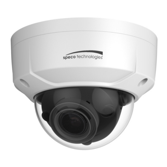
- Page 1 Quick Start Guide 4MP Vandal Dome IP Camera O4D2M...
- Page 2 This owner’s manual is designed to be a reference tool for your system. Please read this manual carefully before operating the unit and retain it for future reference. Should you require any technical assistance, please contact Speco Technologies Technical Support.
- Page 3 Important Safeguards and Warnings . . . . E lectrical safety All installation and operation here should conform to local electrical safety codes. Use a certified/listed 12VDC Class 2 power supply only. Please note: Do not connect two power supplying sources to the device at the same time; it may result in device damage! The product must be grounded to reduce the risk of electric shock.
- Page 4 Speco Technologies is not liable for any loss caused by improper operation. Note: Before installation, check the package and make sure that all components are included. Contact your rep or Speco customer service department immediately if something is broken or missing in the package. Accessory Name...
-
Page 5: Table Of Contents
Table of Contents Structure ..........................1 Port Description ......................1 Dimensions ......................... 2 Bidirectional Audio ..................... 2 1.3.1 Device-end to PC-end ................... 2 1.3.2 PC-end to Device-end ................... 2 Alarm Setup ........................ 3 Device Installation ........................5 Installation Steps ......................5 Micro SD Card Installation................... -
Page 6: Structure
1 Structure 1.1 Port Description You can refer to the following figure for more details. See Figure 1-1 Figure 1-1 Please refer to the following sheet for detailed information. Port Port Name Function Description Zoom W Adjusts lens to wide angle end (image min zoom) RESET Reset button Restores device to factory default. -
Page 7: Dimensions
1.2 Dimensions Please refer to the following figure for dimension information. The unit is mm. See Figure 1-2 Figure 1-2 1.3 Bidirectional Audio 1.3.1 Device-end to PC-end Device Connection First, connect a microphone to the audio input port of the device. Then connect a speaker to the audio output port of the PC. -
Page 8: Alarm Setup
1.4 Alarm Setup Figure 1-3 Alarm input, output description: Step 1 Step 1 Connect alarm input device to the alarm input Connect alarm input device to the alarm input port. Step 2 Step 2 Connect alarm output device to the alarm output Connect alarm output device to the alarm output port. - Page 9 Figure 1-5 Figure 1-6 Mode A: Level application. Alarm output high and low level, alarm output is OC; it needs to increase pull-up resistance externally to work normally. Max external pull-up level is 5V, max port current is 5mA. After external pull-up resistance is increased, the default of output signal is high level (external pull-up voltage), and it switches to low level when there is alarm output (when the working current is 5mA, output voltage is less than 0.8V).
-
Page 10: Device Installation
2 Device Installation Note: Before installation, please make sure the installation surface can support a minimum of 3 times the weight of the camera 2.1 Installation Steps Figure 2-1 Please follow the steps listed below to install the device. Please refer to Figure 2-1 for reference. Step 1 Use star-shaped wrench in the accessories bag to unscrew the three star-shaped screws on the dome enclosure, and then open the dome enclosure. - Page 11 both sides; Hold the IR light decoration cover to rotate horizontally, adjust the image and adjust the lens horizontal direction to the targeted location; Range of adjusting lens angle: vertical rotation direction (0° ~ +65°), horizontal rotation direction (0° ~ + 355°), image horizontal rotation direction (0°...
-
Page 12: Micro Sd Card Installation
2.2 Micro SD Card Installation Note: Please shut down the device before you install a Micro SD card. Step 1 Open the device enclosure according to the step 1 in the device installation. Step 2 Find the “Micro SD” slot in the device; adjust the direction of Micro SD card according to the direction shown on the device and insert the card into the slot. -
Page 13: Ip Scanner
3 IP Scanner IP Scanner can search for the device on the local network. IP Scanner can search for the device on the local network. Please note that only devices that are on the same subnet can be discovered. Please note that only devices that are on the same subnet can be discovered. The device is set to DHCP mode by default. -
Page 14: Web Operation
4 Web Operation This device supports viewing and management via a web browser on a PC. This device supports viewing and management via a web browser on a PC. 4.1 Login and Main Interface Login and Main Interface Open the browser and input network camera address in the address bar or double click the device in IP S Open the browser and input network camera address in the address bar or double click the device in IP Scanner.
Need help?
Do you have a question about the O4D2M and is the answer not in the manual?
Questions and answers