StarTech.com DuraView RACKCONS1708 Instruction Manual
Rack console with kvm switch
Hide thumbs
Also See for DuraView RACKCONS1708:
- User manual (27 pages) ,
- Instruction manual (25 pages)

Subscribe to Our Youtube Channel
Related Manuals for StarTech.com DuraView RACKCONS1708


Summary of Contents for StarTech.com DuraView RACKCONS1708
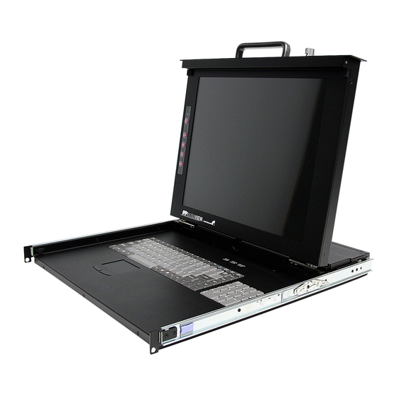
- Page 1 Rack Console with KVM Switch 17” LCD Rackmount Console with 8 Port KVM 19” LCD Rackmount Console with 16 Port KVM RACKCONS1708 Instruction Manual RACKCONS1916 Actual product may vary from photo...
- Page 2 StarTech.com. Where they occur these references are for illustrative purposes only and do not represent an endorsement of a product or service by StarTech.com, or an endorsement of the product(s) to which this manual applies by the third-party company in question.
-
Page 3: Table Of Contents
Package Contents ........1 Accessory Products from StarTech.com ..... . .1 Installation and usage . -
Page 4: Introduction
I I n n t t r r o o d d u u c c t t i i o o n n Thank you for purchasing a StarTech.com LCD Rack Console with KVM. This product allows you to manage multiple computers using an integrated keyboard, mouse, and TFT screen that slides into a compact 1U of rack space when not in use. - Page 5 Instruction Manual SV125 Sun to PS/2 Keyboard/Mouse Converter SVECONUS10 10 ft Ultra-Thin USB 2-in-1 KVM Cable SVECONUS15 15 ft Ultra-Thin USB 2-in-1 KVM Cable SVECONUS6 6 ft Ultra-Thin USB 2-in-1 KVM Cable SVECON10 6 ft. IEEE-1394 FireWire Cable 6-pin to 6-pin SVECON15 15 ft Ultra-Thin PS/2 3-in-1 KVM Cable SVECON25...
-
Page 6: Installation And Usage
I I n n s s t t a a l l l l a a t t i i o o n n a a n n d d u u s s a a g g e e Hardware kit contents Side Rails with front and rear brackets (2) -
Page 7: Mounting The Console
Instruction Manual Mounting the Console 1. Loosen the rear screws (pre-installed in side rails) and adjust the length of the rear bracket to fit the depth of your cabinet: 2. Install the rail into the cabinet: 3. Tighten the screws that were loosened in Step 1: 4. - Page 8 5. Slide the Module onto the Console side rails, connecting the Module and Console using the male Centronics connector provided by the Console, and the female Centronics connector provided by the Module. Ensure the connection is secure, and that the module is firmly seated within the Console side rails. 6.
-
Page 9: Connecting The Console/Module
Instruction Manual 8. Installation is now complete: Connecting the Console/Module To connect the KVM Console/Module to a computer, perform the following steps: 1. Remove the four screws from both sides of the KVM console. Be sure to retain these screws for the next installation step. 2. - Page 10 Instruction Manual 3. From the rear of the cabinet, slide the KVM console onto the mounting rails. 4. Install one screw on each side of the console (as depicted below). Connecting computers to the module Attach each of your managed computers to your StarView KVM console’s PC ports using ultra-thin KVM cables.
-
Page 11: Cascade Configuration
TFT screen. The LED located to the left of the monitor panel should turn from orange to green, verifying that the unit is operational. -
Page 12: Testing The Console
Whenever you change the resolution, color, or refresh rate, the image size, position, or shape may change. This behavior is normal. You can readjust the image using the monitor on-screen controls. For more information on the monitor on-screen controls, refer to Panel controls and OSD functions. For more information on configuring the display settings, please refer to the manual that accompanied your video card. -
Page 13: Auto Tune
Auto tune Press the Auto tune button. The panel will adjust the display size automatically and also tune the panel to its optimized state. Input Source 1. Press the Menu button. 2. Use the Down and Up buttons to scroll. 3. -
Page 14: Color
Color 1. Press the Menu button. 2. Use the Down and Up button to scroll. 3. Highlight Color, and press the Menu button to enter, which will launch the following screen: Icon Description 9300°K To set CIE coordinates at 9300°K color 7500°K To set CIE coordinates at 7500°K color 6500°K... -
Page 15: Language
Language 1. Press the Menu button. 2. Use the Down and Up buttons to scroll. 3. Highlight Language, and press the Menu button to select, which will launch the following screen: English German French Italian Spanish 4. Use the Down and Up buttons to scroll, and highlight the preferred language. -
Page 16: Module Operation
Instruction Manual M M o o d d u u l l e e o o p p e e r r a a t t i i o o n n Push Button Selection A computer may be selected by pressing the push buttons above the keyboard on the Console, by issuing hot-key commands or by activating the OSD window. - Page 17 select it. Or, you may press <ESCAPE> to exit the OSD and remove the OSD menu from the display; the status window returns to the display and indicates the currently selected computer or operating status. A triangle mark to the right of a name indicates the port is cascaded to a Slave; the number at the left of the triangle mark shows the number of ports the Slave has, i.e.
- Page 18 Function key <F4> - More functions are available by hitting <F4>. A new screen pops up displaying more functions as described below. Most of them are marked with a triangle ( ) indicating there are options to choose from. Using the < > and < > arrow keys, select the functions and press <ENTER>.
-
Page 19: Hot-Key Commands
the Keyboard Speed setting. Hotkey Menu When you hit the left <CTRL> key twice within two seconds, the Hotkey Menu appears displaying a list of hot-key commands if the option is On. The Hotkey Menu can be turned Off if you prefer not to see it when the left <CTRL> key is hit twice. - Page 20 Left Ctrl + left Ctrl + 7 Selects a computer connected to port 7 of the Master. Left Ctrl + left Ctrl + 6 + C Selects a computer connected to port C of a Slave connected to port 6 of the Master.
- Page 21 Instruction Manual Change Configuration while Running A device (a computer or a KVM switch) at any 'PC x' port can be changed at any time after initial power-up. If you change any one of the PC 1 to PC 8 ports connection from a computer to a Slave or vice versa, or replace the devices of a port, the OSD will update this change the next time it is activated.
-
Page 22: Power Indicator
S S p p e e c c i i f f i i c c a a t t i i o o n n s s RACKCONS1708 Certifications 8 x VGA female input 1 x VGA female output Connectors 1 x PS/2 Keyboard 6-pin Mini-Din (Female) -
Page 23: Limitation Of Liability
Limitation of Liability In no event shall the liability of StarTech.com Ltd. and StarTech.com USA LLP (or their officers, directors, employees or agents) for any damages (whether direct or indirect,... - Page 24 Visit www.startech.com for complete information about all our products and to access exclusive interactive tools such as the Parts Finder and the KVM Reference Guide. StarTech.com makes it easy to complete almost any IT solution. Find out for yourself why our products lead the industry in performance, support, and value.
Need help?
Do you have a question about the DuraView RACKCONS1708 and is the answer not in the manual?
Questions and answers