Table of Contents
Advertisement
Quick Links
Advertisement
Chapters
Table of Contents

Subscribe to Our Youtube Channel
Related Manuals for Beckhoff CP79-14 Series


Summary of Contents for Beckhoff CP79-14 Series
- Page 1 Manual | EN CP79xx-14xx Control Panel 2023-1-31 | Version: 1.0...
-
Page 3: Table Of Contents
Table of contents Table of contents 1 Notes on the documentation........................ 5 2 For your safety ............................ 6 Description of safety symbols ...................... 6 Intended use ............................. 6 Fundamental safety instructions ....................... 7 Operator's obligation to exercise diligence.................. 7 Notes on information security...................... 8 3 Product overview ............................ - Page 4 Table of contents Version: 1.0 CP79xx-14xx...
-
Page 5: Notes On The Documentation
Copyright © Beckhoff Automation GmbH & Co. KG. Publication of this document on websites other than ours is prohibited. Offenders will be held liable for the payment of damages. All rights reserved in the event of the grant of a patent, utility model or design. -
Page 6: For Your Safety
Exclusion of liability Beckhoff shall not be liable in the event of non-compliance with this documentation and thus the use of the devices outside the documented operating conditions. -
Page 7: Fundamental Safety Instructions
For your safety Fundamental safety instructions The following safety instructions must be observed when handling the device. Application conditions • Do not use the device under extreme environmental conditions. Protect the device from heat. • Never use the device in potentially explosive atmospheres. •... -
Page 8: Notes On Information Security
For your safety Notes on information security The products of Beckhoff Automation GmbH & Co. KG (Beckhoff), insofar as they can be accessed online, are equipped with security functions that support the secure operation of plants, systems, machines and networks. Despite the security functions, the creation, implementation and constant updating of a holistic security concept for the operation are necessary to protect the respective plant, system, machine and networks against cyber threats. -
Page 9: Product Overview
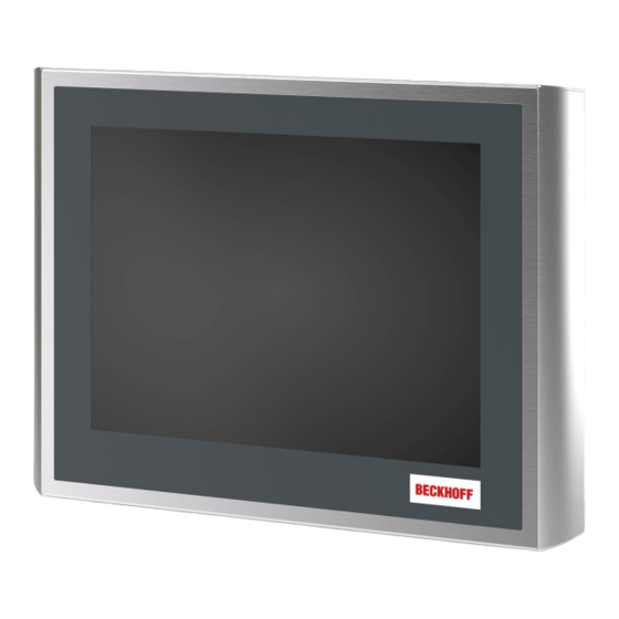
Product overview Product overview The stainless steel control panel is designed for installation on the mounting arm. It offers suitable solutions for a variety of applications. The model variety ranges from different display sizes to custom models. The control panel has the following features: •... -
Page 10: Structure
Product overview Structure Fig. 2: CP79xx-14xx_structure Table 1: Legend CP79xx-14xx structure Component Description Display and touch screen glass Operating the control panel Stainless steel front Use in environments with higher hygiene requirements Threaded bolts Bolts for installation on the mounting arm system Connection compartment Access to the interfaces Version: 1.0... -
Page 11: Interface Description
Product overview Interface description The number of interfaces of the control panel varies depending on whether the device is equipped with a push button extension. The following table provides information about the interfaces of the device without and with push button extension. Table 2: Interface assignment CP79xx-14xx Control Panel Interfaces... -
Page 12: Fig. 4 Cp79Xx-14Xx_Disassembly Cover
Product overview Fig. 4: CP79xx-14xx_Disassembly cover Version: 1.0 CP79xx-14xx... -
Page 13: Dvi Extended Input
Product overview 3.2.1 DVI Extended input The control panel has a DVI Extended input (X101) according to IP65. It is used to transmit the graphics signal from the industrial PC to the control panel. The graphics signal is transferred directly via a DVI cable over a distance of 50 m max. Such a cable length leads to strong distortion of the graphics signal on arrival at the control panel. -
Page 14: Power Supply
The plug is included in the delivery. You can obtain a replacement plug from your Beckhoff Sales using the following ordering option: • C9900-P916: power supply connector for CP79xx, round connector IP65 with strain relief for the external supply cable 3.2.3... -
Page 15: Emergency Stop And Push Button Connection
Product overview 3.2.4 Emergency stop and push button connection The CP79xx-1401 Control Panels with integrated push button extension have an additional connection (XS01) at the rear side in the connection section. The 19-pin M23 connector can be used to connect the emergency stop button and the three electromechanical push buttons S2-S4 of the push button extension. -
Page 16: Name Plate
Product overview Name plate The name plate provides information about the control panel equipment. The name plate shown here serves only as an example. xxxxxxx Fig. 9: CP79xx-14xx_name plate Table 7: Legend for CP79xx-14xx name plate Description Model Serial number (BTN) Date of manufacture Display Touch screen Touch pad... -
Page 17: Connection Cables/Connection Kits
Product overview Connection cables/connection kits Ready-made connection cables for connecting emergency stop and push buttons (XS01) as well as connection kits for the DVI-E/USB-E 2.0 connection are available. Table 8: Connection cable XS01 Connection cable Description C9900-K604 Signal and power supply cable for CP770x-1401 and CP790x-1401, length 10 m, 18 x 0.75 mm , pre-assembled, M23 socket IP65, screwable, 19-pin, second end open C9900-K593... -
Page 18: Commissioning
If you, as the user, require additional protection for the touch screen against dirt and scratching, for example due to dirty hands, this can be achieved with a Beckhoff protective film. The film provides short-term protection for a few days. -
Page 19: Transport And Unpacking
5. Check the contents for visible shipping damage. 6. In case of discrepancies between the package contents and the order, or in case of transport damage, please inform Beckhoff Service (see Chapter 9.1 Service and Support [} 30]). CP79xx-14xx Version: 1.0... -
Page 20: Mounting
The control panel is designed for installation on a mounting arm system. There are eight M6 x 20 threaded bolts on the back of the unit for mounting. The dimensions of the device can be found on the Beckhoff website: https://www.beckhoff.com/de-de/support/downloadfinder/technische-zeichnungen/. All dimensions are in mm. -
Page 21: Fig. 11 Cp79Xx-14Xx_Installation Mounting Arm Tube
Fig. 11: CP79xx-14xx_installation mounting arm tube Alternatively, you can order a ready-configured mounting arm tube with already welded connection piece from Beckhoff: • C9900-M167: Adapter with welded tube (length: 1.50 m, diameter: 48 mm) for mounting arm adapter C9900-M177 or C9900-M178 on CP790x-140x Control Panel. Stainless steel 1.4301, brushed... -
Page 22: Connecting The Control Panel
If you have equipped your device with a Beckhoff mounting arm adapter, you will find the information for accessing the connections in Chapter 3.2 Interface description [} 11]. -
Page 23: Connecting Cables And Power Supply
The connections are located at the rear in the connection section of the device. If you have equipped your device with a Beckhoff mounting arm adapter, you will find the information for accessing the connections in Chapter 3.2 Interface description [} 11]. -
Page 24: Decommissioning
Decommissioning Decommissioning NOTE Hardware damage due to power supply A connected power supply can cause damage to the control panel during disassembly. • Disconnect the power supply from the device before starting to disassemble it. When taking the control panel out of operation, you must first disconnect the power supply and cables. You can then dismantle the device. -
Page 25: Disassembly And Disposal
Decommissioning Disassembly and disposal Before you can remove the control panel from the mounting arm, you must first disconnect the power supply and the cables (see chapter 5.1 Disconnecting the power supply and cables [} 24]). NOTE Damage to property due to falling down If the control panel hangs from the ceiling and you start disassembly from the mounting arm without secur- ing it, the control panel will fall down. -
Page 26: Maintenance
Cleaning the front screen You can clean the front screen of the control panel during operation. In order to avoid inadvertent touch entries when doing this, you must first set the device to "Cleaning Mode" with the help of the Beckhoff Control Tool. -
Page 27: Fig. 14 Cp69Xx_Select Cleaning Mode
5 and 120 seconds. Right-click the sun symbol again and click "Options". Now select the appropriate period (see fig. 15). Fig. 15: CP69xx_Options Repair Only the vendor may repair the device. If a repair should be necessary, contact Beckhoff Service (see Chapter 9.1 Service and Support [} 30]). CP79xx-14xx Version: 1.0... -
Page 28: Troubleshooting
Cycle time in TwinCAT set to 10 ms Increase the cycle time to TwinCAT via USB (standard) between 50 ms and 80 ms No picture/backlight Problem with the cable connections Check the cable connection Beckhoff recommends using Beckhoff connection cables and connection kits. Version: 1.0 CP79xx-14xx... -
Page 29: Technical Data
Technical data Technical data Table 12: Technical data Product designation CP79xx-14xx Weights without / with mounting CP7901-1400: 5.3 kg / 7.2 kg arm adapter CP7901-1401: 7.0 kg / 8.9 kg CP7902-1400: 7.2 kg / 9.1 kg CP7902-1401: 8.9 kg / 10.8 kg CP7903-1400: 10.6 kg / 12.5 kg CP7903-1401: 12.3 kg / 14.2 kg Supply voltage 20.4-30 V (24 V... -
Page 30: Appendix
Telephone: + 49 (0) 5246/963-0 Fax: + 49 (0) 5246/963-198 email: info@beckhoff.de The addresses of the worldwide Beckhoff subsidiaries and agencies can be found on our website at http:// www.beckhoff.com/. You will also find further documentation for Beckhoff components there. -
Page 31: Approvals
Appendix Approvals The Control Panel has the following approvals: • CE • EAC • UKCA • FCC You will find all other applicable approvals on the name plate of your device. FCC approvals for the United States of America FCC: Federal Communications Commission Radio Frequency Interference Statement This device was tested and complies with the limits for a digital device of class A, according part 15 of the FCC regulations. - Page 32 List of figures List of figures Fig. 1 CP79xx-14xx_without and with push button extension..............Fig. 2 CP79xx-14xx_structure........................ Fig. 3 CP79xx-14xx_connection section ....................Fig. 4 CP79xx-14xx_Disassembly cover....................Fig. 5 CP79xx-14xx_DVI Extended input pin numbering ............... Fig. 6 CP79xx-14xx_voltage socket pin numbering ................Fig.
- Page 33 List of tables List of tables Table 1 Legend CP79xx-14xx structure....................Table 2 Interface assignment CP79xx-14xx ..................... Table 3 DVI extended interface pin assignment ..................Table 4 Voltage socket pin assignment ....................Table 5 USB E input pin assignment ......................Table 6 XS01 pin assignment ........................Table 7 Legend for CP79xx-14xx name plate...................
- Page 35 More Information: www.beckhoff.com/de-de/produkte/ipc/control-panels/cp39xx- cp79xx-edelstahl-control-panels Beckhoff Automation GmbH & Co. KG Hülshorstweg 20 33415 Verl Germany Phone: +49 5246 9630 info@beckhoff.com www.beckhoff.com...
Need help?
Do you have a question about the CP79-14 Series and is the answer not in the manual?
Questions and answers