Table of Contents
Advertisement
Quick Links
Advertisement
Table of Contents

Subscribe to Our Youtube Channel
Related Manuals for Transcell Technology TI-1500


Summary of Contents for Transcell Technology TI-1500
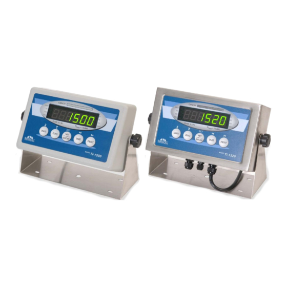
- Page 1 Digital Weight Indicator Setup / Operation Manual Revision 1.71 February 25, 2009...
-
Page 2: Table Of Contents
©Transcell Technology, Inc. 2009. All rights reserved. The information contained herein is the property of Transcell Technology and is supplied without liability for errors or omissions. No part may be reproduced or used except as authorized by contract or other written permission. The copyright and the foregoing restriction on reproduction and use extend to all media in which the information may be embodied. -
Page 3: Introduction
All setup parameters may be entered via the front panel keys, including calibration. If your Model TI-1500 Series Digital Indicator is part of a complete floor scale or has already been installed for you, you may skip to the operating instructions. Prior to using the indicator, please read this chapter carefully and completely. -
Page 4: Installation
Electrical Power The TI-1500 indicators have been designed to operate from 100 to 240 VAC at 50/60 Hz. All units ship with the appropriate power plug for its area of intended use. To avoid electrical noise interference and/or stray AC electrical transients, try to operate the indicator from a circuit separate from any equipment containing inductive devices such as a contactor coil, solenoid, relay coil, or motor. -
Page 5: Connecting The Weigh Platform
CONNECTING THE WEIGH PLATFORM The TI-1500 model ships with a 15 ft shielded load cell cable for connection to weigh platform’s load cell(s) or junction box. 1. Plug the cable’s 14-pin parallel interface connector into the load cell port on the rear panel of the indicator. -
Page 6: Configuration
CONFIGURATION OVERVIEW The indicator contains two main configuration menus: The Setup (“F”) menu, which configures the indicator to your weigh platform The User (“A”) menu, which configures the serial communication port and enables some user options The Setup and User menus consist of several menu selections, each with its own sub-menu of selections or programming procedures. -
Page 7: Menu Structure
MENU STRUCTURE All menus consist of a top level (heading) and a secondary level. The top level contains the code (e.g. F1) for the parameter to be configured. The secondary level contains the selection list or allows access to a programming sequence. - Page 8 CODE/NAME DESCRIPTION SELECTION LIST Sets the level at which motion is detected. If motion is not detected, Key-in the scale can process a Print or Zero command. Maximum value 0.0d/s – 32.0d/s Motion Band varies depending on local regulations. Expressed as scale divisions per second (d/s).
-
Page 9: Setup Menu Procedures
CODE/NAME DESCRIPTION SELECTION LIST This sub-menu will reset all parameters in the “F” and “A” menu to the Press the ZERO Factory Reset default settings for North America. USE WITH CAUTION! key twice to North America execute. This sub-menu will reset all parameters in the “F” and “A” menu to the Press the ZERO default settings for Europe. -
Page 10: User Menu Descriptions
USER MENU DESCRIPTIONS This section provides more detailed descriptions of the selections found in the User Menu Chart. Factory-set defaults are shown in bold; (NA) for North America and ( ) for Europe. € CODE/NAME DESCRIPTION SELECTION LIST Selects the baud rate for data transmission through the serial port. 300, 600, 1200, 2400, 4800, Baud Rate... -
Page 11: User Menu Procedures
USER MENU PROCEDURES This section provides instructions for all of the User Menu procedures. ID Number Entry (A8) 1. While in the User Menu mode, scroll to "A 8", then scroll down once using the ZERO key to enter the ID Number menu. 2. -
Page 12: Exiting The Menus
Set Date (A16) Your indicator will keep track of the current date for you, which can then be printed on the print ticket. Use this procedure to set the date, which must be set in mm/dd/yy format. For example, for January 7, 2008, you would enter 010708. -
Page 13: Calibration
CALIBRATION CALIBRATION OVERVIEW If your indicator was shipped as a complete scale, then calibration is not necessary. Please check with your installer or supplier if you are unsure. Transcell recommends having your weighing equipment checked by a qualified scale technician at least once a year depending on its intended use and working environment. -
Page 14: View Calibration Values (F18)
6. At this time it is suggested that the calibration values be recorded for future use (see next section). If the calibration was not successful, one of the error messages below will appear. Take the indicated action to correct the problem, then perform a new calibration. "Err0"... -
Page 15: Key-In Zero Calibration Value (F19)
KEY-IN ZERO CALIBRATION VALUE (F19) Note: This procedure is intended for emergency use only in the case of non-volatile memory loss. A valid zero calibration value, obtained from a successful F16 calibration procedure, must be used. 1. While in the Setup mode, scroll to "F 19", then scroll down once using the ZERO key. The display will momentarily show "ET C 0", followed by a value of zero 2. -
Page 16: Operation
PCS Indicates the unit of the displayed weight. PCS stands for “pieces”. STABLE This light is on whenever the scale is stable. TABLE 4: TI-1500 Annunciator Definitions KEYBOARD The keyboard is composed of five function keys shown below. ZERO... -
Page 17: Function Keys
FUNCTION KEYS Units – This key toggles the indicator among the available weight units if enabled in the User (“A”) menu. Available weight units include lb, kg and pieces.. Zero - This key sets the indicator to display zero provided the following conditions are met: 1. -
Page 18: Peak Hold Mode
To activate this mode, set F30 to 2. This mode is used to emulate a remote display for a separate indicator. For it to work properly, a remote indicator must be transmitting information to the TI-1500 continuously and at the same transmission (baud) rate configured in A1. -
Page 19: Legal For Trade Sealing
2. On the back of the indicator, locate the setup/calibration switch cover. 3. Thread a wire security seal through both drilled head screws securing the calibration switch cover as well as two single drilled head screws holding on the rear panel. TI-1520 shown – TI-1500 similar... -
Page 20: Appendix A: Specifications
-25° to +70 C MECHANICAL Overall Dimensions (L x W x H) – 8.5" x 3.0" x 4.6" (215mm x 75mm x 117mm) TI-1500 Overall Dimensions (L x W x H) – 10.4" x 3.1" x 7.7" (265mm x 80mm x 195mm) TI-1520... -
Page 21: Appendix B: Serial Port Information
APPENDIX B: SERIAL PORT INFORMATION SERIAL PORT MODES DEMAND DUPLEX MODE The Demand Duplex Mode provides a two way serial transmission mode In this mode, the output information is transmitted on demand; either by pressing the PRINT key on the indicator’s front panel or upon receiving a recognized command from a host device (i.e. -
Page 22: Output String
OUTPUT STRING The indicator contains one editable output string (print format). You can simply choose one of three output strings already created for you or you can edit one of the pre-defined output strings to suit your application. Output strings are created by assigning a hexadecimal value to a decimal address. The addresses start at 0 (displayed as 00) and end at 94. -
Page 23: Text Print Ticket
TEXT PRINT TICKET The Text Print Ticket is designed specifically for a serial printer. ID.NO. 123456 DATE 01/28/09 TIME 10:23 AM GROSS 1067 lb TARE 67 lb 1000 lb Address Value Chart Address Value Charts (Dec) (Hex) (Dec) (Hex) (GWT) (UN) (PRID) ‘... -
Page 24: String Format 1 (Condec Demand String)
STRING FORMAT 1 (Condec Demand String) String Format 1 is designed for two-way communication. <STX> <POL> xxxxx.xx <SP> <LB/KG> <SP> <GR/NT> <CR> <LF> Start Weight Data Space Space Carriage Transmission Return Units: Gross/Net: Line Polarity: LB = pound GR = Gross Feed <SP>... -
Page 25: String Format 2 (Condec Continuous String)
STRING FORMAT 2 (Condec Continuous String) String Format 2 is designed for one-way communication, e.g. remote display. <STX> <POL> xxxxx.xx <L/K> <G/N> <STAT> <CR> <LF> Gross/Net: Start Weight Data Carriage G = Gross Transmission Return N = Net Polarity: Line <SP>... - Page 26 Edit Output String (A31) The programming format is AA__vv where AA is the address (00 to 94) and vv is the programming value (remember a value can be either a printable ASCII character or a print command.) 1. While in the User Menu mode, scroll to "A 31", and then scroll down once using the ZERO key to enter the edit output string menu.
-
Page 27: Appendix C: Displayed Error Codes
APPENDIX C: DISPLAYED ERROR CODES CODE MODE MEANING / POSSIBLE SOLUTION Normal Operating Gross Overload. A weight greater than the rated capacity has been Mode applied to the scale. Remove the weight from the platter or try re- calibrating the scale. Otherwise, check for a bad load cell connection or possible load cell damage due to overloading.
Need help?
Do you have a question about the TI-1500 and is the answer not in the manual?
Questions and answers