Table of Contents
Advertisement
Quick Links
Advertisement
Table of Contents

Related Manuals for Armedica AM-702


Summary of Contents for Armedica AM-702
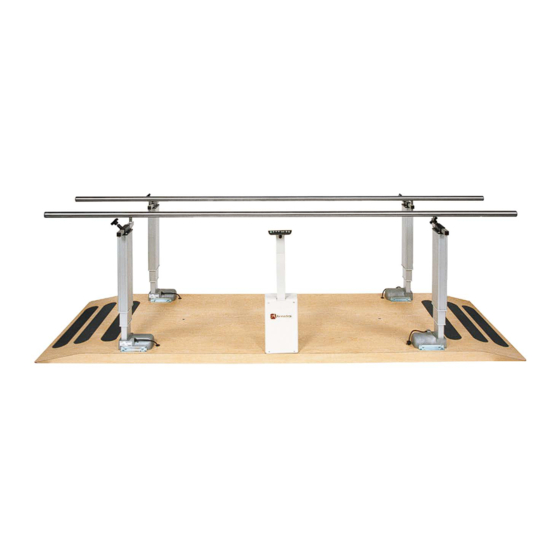
- Page 1 This manual has been prepared for the owners and operators of the ARMEDICA™ AM-700 Series Parallel Bars and contains installation instructions, precautionary instructions and maintenance procedures for the following model numbers: AM-700, AM-702, AM-703, AM-705, AM-706, AM-706HD...
-
Page 2: Table Of Contents
This User's Manual is for the following AM-700 series Parallel platforms only AM-700 - Electric platform mount 10'x43" AM-702 - Electric platform mount 7'x43" AM-703 - Electric platform mount 15'x43" AM-705 - Electric bariatric platform mount 10'x49-1/2" AM-706 - Electric bariatric platform mount 10'X49-1/2"... -
Page 3: Symbols And Indicators
SYMBOLS and INDICATORS WARNING: Read and understand the operating instructions listed in this manual before installing or using this equipment. Failure to follow manufacturer's operating instructions could result in equipment damage or personal injury. ATTENTION: Important information or instructions. WARNING: Follow safe lifting procedures and precautions. WARNING: Identifies electrical shock hazard. -
Page 4: Definitions
Specific instructions for operation of the AM-700 series can be found in this manual. If further training on the operation of the AM-700 is required, it is available by contacting Armedica Mfg. customer service. CAUTION: A patient is not intended to operate this device in any way. - Page 5 Applied part: An applied part is one specifically intended to come into direct contact with patient during normal use. This includes Armedica part #'s 18628, 28320, 18627, 14601, 14605, 14609, 14610 and 14615 only. Applied parts are identified, either in this manual or directly on the part, with this symbol...
-
Page 6: Assembly And Installation
AM SERIES ELECTRIC PARALLEL BARS WARNING: Read and understand this operator’s manual before installing or using this equipment. Failure to follow operating and maintenance instructions could result in equipment damage or personal injury. ELECTRIC PARALLEL BARS INSTALLATION ALL MODELS WARNING: 4 people are required to move this equipment. This unit weighs in excess of 500lbs/1100kg. - Page 7 SCU CONTROLLER 1. SCU CONTROLLER 2. AC MAINS PORT 3. SWITCH PORT 4. PROTECTIVE EARTH TERMINAL 5. MOTOR PORT M1 6. MOTOR PORT M2 7. MOTOR PORT M3 8. MOTOR PORT M4 CAUTION: All cables must be fully inserted into their appropriate receptacles on control box and columns.
- Page 8 CABLE CONNECTIONS • Connect the four cables (36) and (37) (DIN8 connectors) to the appropriate column (13). • Remove cover from the lower section of the SCU controller by rotating the lock screw, located on the front of the cover, to the “UNLOCK” position. Slide cover down to remove. •...
-
Page 9: Operating Instructions
INTENDED POSITIONS Patient position Operator position This unit has been initialized by Armedica Manufacturing Corp. prior to shipment and should not need to be synchronized again unless a column or control box is replaced. If Synchronization becomes necessary, follow these steps: INITIAL RESET FOR MOTORS •... -
Page 10: Maintenance
ARMEDICA™ Manufacturing thoroughly inspects and tests each unit to ensure that it meets all ARMEDICA™ quality standards before it leaves the facility. To ensure the longevity of your device, routine maintenance should be followed. - Page 11 CAUTION: Service to controls and column motors is to be done by the manufacturer only. In the event of a column motor or control unit failure, all 4 columns and control unit must be returned to Armedica Manufacturing Corp. WARNING: Do not alter or modify this device in any way.
-
Page 12: Technical Specifications
Operating/storage temp. 5°C – 40°C / 41°F – 104°F Humidity: 5% to 85% Pressure/altitude: 700hPa to 1060hPa GENERAL SPECIFICATIONS Manufactured and assembled by Armedica Manufacturing Corp. Greenwood, Arkansas, USA Tel.: (479) 996-2612 Static & Dynamic load capacity Max 500Lbs/227Kgs per bar, not exceeding 500Lbs/227Kgs total combined load. -
Page 13: Parts List And Drawings
ITEM NO. PART NO. DESCRIPTION QUANTITY MODEL NUMBERS 706HD 14601 BD PLL COLMN PLATFORM LAMNTD 28156 PLATE 1/4x4-3/4x6-1/2 PLL COLMN MNT PLTD 03021 SCREW TAPTITE M6X25 TUBE 1x1x14GAx13 PLL RAIL ATTACH 11601 SPACER 5/16 X 3/16 ID x 1/2 OD 02146 NUT NYLOCK 8-32 02093... - Page 20 AM-715 BALANCE BEAM PART ITEM NO. DESCRIPTION QTY. NUMBER 14604A BD PLL BAL BEAM 2-1/2X5X80 13003A SCREW 3/-16x3 MODIFIED 2-3/8 PIN AM-714 ABDUCTION BOARD ITEM NO. PART NUMBER DESCRIPTION QTY. 14603A BD PLL ABDUCTION 3/4X5X94 18667 BRKT YOKE PLL BD PIN PLTD 02044 SCREW HX HD CAP 1/4-20x1-1/4 02084...
- Page 22 ARMEDICA™ Manufacturing Corp. or the selling Dealer will repair or replace the unit without charge within a 30 day period from the date on which the unit is returned to ARMEDICA™ Manufacturing Corp. or the selling Dealer. ARMEDICA™ Manufacturing Corp. has a policy of continuous improvement that may result in changes to specifications at any time.
-
Page 23: Maintenance Log
MAINTENANCE NAME DATE PERFORMED MAINTENANCE PERFORMED...
Need help?
Do you have a question about the AM-702 and is the answer not in the manual?
Questions and answers