Advertisement
Quick Links
Advertisement

Related Manuals for Armedica AM-700 Series


Summary of Contents for Armedica AM-700 Series
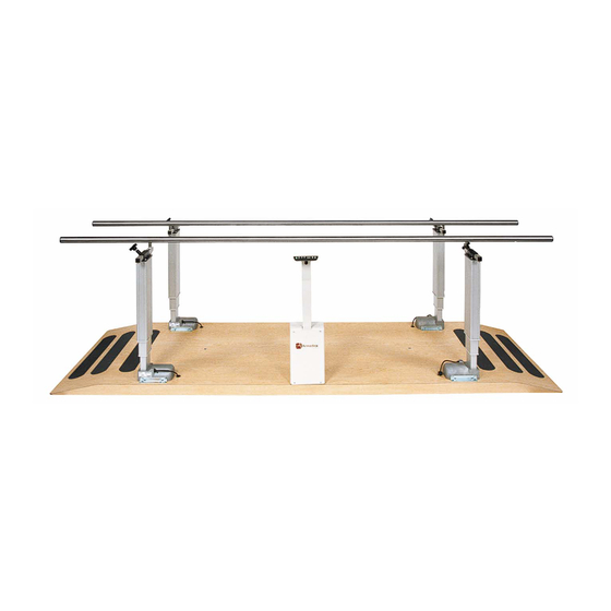
- Page 1 This manual has been prepared for the owners and operators of the ARMEDICA™ AM-700 Series Parallel Bars and contains installation instructions, precautionary instructions and maintenance procedures for the following model numbers: AM-700, AM-707, AM-710, AM-711, AM-712, AM-714, AM-715, AM-716...
- Page 2 AM-700 SERIES PARALLEL BARS ELECTRIC PARALLEL BARS INSTALLATION AM-700 1. Remove platform (1) from crate using handles attached to mounting brackets. (See item #66 on AM700 installation diagram). 4 people are required. (9). Set the platform on supports to get it off the floor far enough to allow access to the bottom of the platform while installing control stand.
-
Page 3: Installation Diagram
ITEM PART DESCRIPTION 14601 PLATFORM 18628 STAINLESS STEEL RAIL ASSEMBLY 03182 TMD CONTROLLER/POWER SUPPLY 03181 TMD COLUMN 13056 SPACER BUSHING 03165 NYLON WASHER 1/2 ID 02095 NUT NYLOCK JAM 1/2-13 02031 HEX HEAD SCREW 8MM-1.25X14Z 12633 COLUMN MOUNTING BRACKET 03183 CONTROL SWITCH 18672 CONTROL STAND... - Page 4 SYNCHRONIZATION AND CALIBRATION UNPLUG POWER CORD BEFORE DISCONNECTING ANY OTHER CABLES This unit has been initialized by Armedica Manufacturing Corp. prior to shipment and • should not need to be synchronized again unless a column or control box is replaced. If it...
-
Page 5: Maintenance
C. In the event the columns become unsynchronized, contact customer service at Armedica Mfg. If there is a failure of one or more of the columns, the control box and the columns must be returned to Armedica Mfg. Corp. Only the manufacturer can service the unit. POWER AM-700 SPECIFICATIONS Magnetic Corp., Olney, Illinois 62450... - Page 6 FLOOR MOUNTED PARALLEL BARS INSTALLATION AM-711, AM-712 NOTICE: Armedica does not supply floor mounting hardware. A qualified professional should install the Floor Mounted Parallel Bars using hardware appropriate for the flooring material. Reference the floor layout drawing on page 9 to position the parallel bar support assemblies on the floor.
- Page 7 PARTS LIST ITEM PART NO. DESCRIPTION power manual 14601 PLATFORM ELECTRIC PARALLEL BAR 18628 HAND RAIL ELECTRIC PARALLEL BAR 03182 CONTROLLER/POWER SUPPLY TMD 03181 LIFTING COLUMN AUTOMATIC PARALLEL 13056 CONTROL ROD BUSHING 3/4"ODx1-1/8 02165 NYLON WASHER 1/2 ID 02095 NYLOCK JAM NUT 1/2-13 02031 HEX HEAD SCREW 8MM-1.25x14Z 12633...
- Page 8 AM-700, AM-702 PARALLEL BARS COVER PLATE...
-
Page 12: This Warranty Does Not Cover
ARMEDICA™ Manufacturing Corp. or the selling Dealer will repair or replace the unit without charge within a 30 day period from the date on which the unit is returned to ARMEDICA™ Manufacturing Corp. or the selling Dealer. ARMEDICA™ Manufacturing Corp. has a policy of continuous improvement that may result in changes to specifications at any time.
Need help?
Do you have a question about the AM-700 Series and is the answer not in the manual?
Questions and answers