Table of Contents
Advertisement
Quick Links
TCD210224AC
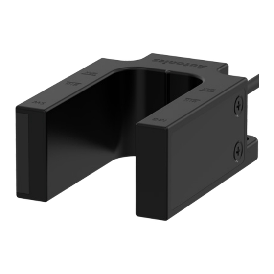
U-shaped Magnetic
Proximity Sensor
MU Series
PRODUCT MANUAL
For your safety, read and follow the considerations written in the instruction
manual, other manuals and Autonics website.
The specifications, dimensions, etc. are subject to change without notice for product
improvement. Some models may be discontinued without notice.
Features
• Non-voltage magnetic detection method
• Two wiring specifications of cable / cable connector type
• IP67 protection structure (IEC standard)
ᜢ
Safety Considerations
• Observe all 'Safety Considerations' for safe and proper operation to avoid hazards.
• symbol indicates caution due to special circumstances in which hazards may occur.
Warning
Failure to follow instructions may result in serious injury or death.
01. Fail-safe device must be installed when using the unit with machinery that
may cause serious injury or substantial economic loss. (e.g. nuclear power
control, medical equipment, ships, vehicles, railways, aircraft, combustion
apparatus, safety equipment, crime/disaster prevention devices, etc.)
Failure to follow this instruction may result in personal injury, economic loss or fire.
02. Do not use the unit in the place where flammable/explosive/corrosive gas,
high humidity, direct sunlight, radiant heat, vibration, impact, or salinity
may be present.
Failure to follow this instruction may result in explosion or fire.
03. Do not disassemble or modify the unit.
Failure to follow this instruction may result in fire.
04. Do not connect, repair, or inspect the unit while the load is connected to a
power source.
Failure to follow this instruction may result in fire.
05. Check 'Connections' before wiring.
Failure to follow this instruction may result in fire.
Caution
Failure to follow instructions may result in injury or product damage.
01. Use the unit within the rated specifications.
Failure to follow this instruction may result in fire or product damage.
02. Use a dry cloth to clean the unit, and do not use water or organic solvent.
Failure to follow this instruction may result in fire.
03. Make cable length as short as possible.
Failure to follow this instruction may result in malfunction.
04. Do not install the switch on the magnetic object or in the environment of
ferromagnetic fields. Use bolt and nut of stainless steel or nonmagnetic
material, when installing the switch.
Failure to follow this instruction may result in malfunction or affect sensing
distance.
05. Do not use a load over the range of rated relay specification.
Failure to follow this instruction may result in fire, relay broken, contact melt,
insulation failure or contact failure.
Cautions during Use
• Follow instructions in 'Cautions during Use'. Otherwise, it may cause unexpected
accidents.
• If excessive shock or vibration is applied to the product, it may cause bounce or
malfunction.
• Use the slow mode filter to avoid bounce and chattering. Bounce and chattering
may occur when high-speed mode (≤ 1 ms) filter is applied.
• This unit may be used in the following environments.
- Indoors (in the environment condition rated in 'Specifications')
- Altitude max. 2,000 m
- Pollution degree 3
- Installation Category Ⅱ
Product Components
• Product
• Instruction manual
Advertisement
Table of Contents

Related Manuals for Autonics MU Series


Summary of Contents for Autonics MU Series
- Page 1 For your safety, read and follow the considerations written in the instruction • This unit may be used in the following environments. manual, other manuals and Autonics website. - Indoors (in the environment condition rated in 'Specifications') The specifications, dimensions, etc. are subject to change without notice for product - Altitude max.
- Page 2 Dimensions This is only for reference, the actual product does not support all combinations. • Unit: mm, For the detailed dimensions of the product, follow the Autonics web site. For selecting the specified model, follow the Autonics website. ■ MU-□-30 ■...
- Page 3 • Install the switch to the position where the target passes the sensing point area. Sensing point area: area between 30 mm point and 40 mm point from the end of the switch Sensing point area MAX MIN 0 18, Bansong-ro 513Beon-gil, Haeundae-gu, Busan, Republic of Korea, 48002 www.autonics.com | +82-2-2048-1577 | sales@autonics.com...
Need help?
Do you have a question about the MU Series and is the answer not in the manual?
Questions and answers