
Subscribe to Our Youtube Channel
Related Manuals for Hoshizaki B Series


Summary of Contents for Hoshizaki B Series
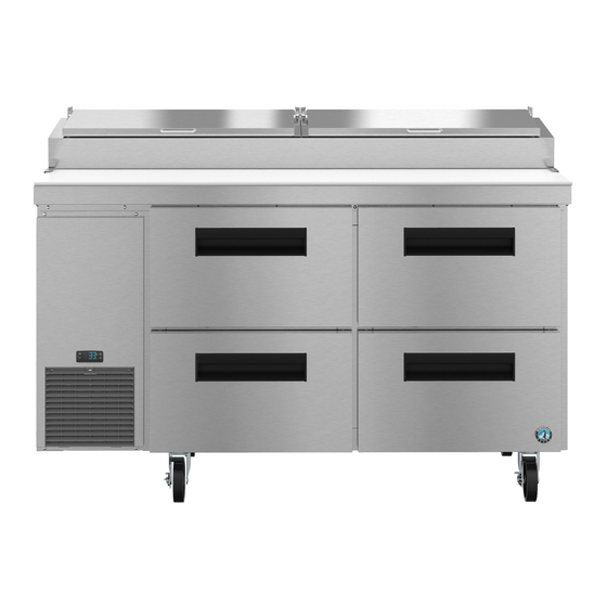
- Page 1 Instruction Manual Refrigerated Kitchen Equipment Steelheart B Series Models Refrigerated Prep Table with Raised Rail hoshizakiamerica.com Issued: 8-10-2022 Revised: 9-15-2022...
- Page 2 Should the reader have any questions or concerns which have not been satisfactorily addressed, please call, send an e-mail message, or write to the Hoshizaki Technical Support Department for assistance. Phone: 1-800-233-1940; (770) 487-2331 Fax: 1-800-843-1056;...
-
Page 3: Table Of Contents
IMPORTANT This manual should be read carefully before the appliance is installed and operated. Read the warnings and guidelines contained in this booklet carefully as they provide essential information for the continued safe use and maintenance of the appliance. Retain this booklet for any further reference that may be necessary. CONTENTS Important Safety Information .................... - Page 4 B. Maintenance ........................ 44 1. Air Filter ........................44 2. Condenser ......................44 3. Condensate Drain Hose ..................44 4. Power Supply Connection ..................44 IV. Preparing the Appliance for Periods of Non-Use ............45 V. Disposal ........................... 46...
-
Page 5: Important Safety Information
Important Safety Information Throughout this manual, notices appear to bring your attention to situations which could result in death, serious injury, damage to the appliance, or damage to property. Indicates a hazardous situation that, if not avoided, will result in DANGER death or serious injury. - Page 6 • THE APPLIANCE MUST BE WARNING GROUNDED. The appliance is equipped The appliance should be destined only to with a NEMA 5-15 three-prong grounding the use for which it has been expressly plug to reduce the risk of potential conceived. Any other use should be shock hazards.
- Page 7 • Do not block air inlets or outlets, otherwise WARNING, continued cooling performance may be reduced. • Children should be properly supervised • Do not tightly pack the cabinet. Allow some around the appliance. space between items to ensure good air •...
- Page 8 NOTICE • Protect the floor when moving the appliance to prevent damage to the floor. • Keep ventilation openings clear of obstruction. • The factory-installed rear bumpers must be in place to ensure proper rear clearance. Blockage of airflow could negatively affect performance and damage the appliance.
-
Page 9: Installation Instructions
I. Installation Instructions WARNING • The appliance must be installed in accordance with all applicable national, state, and local regulations. • Appliance is heavy. Use care when lifting or positioning. Work in pairs when needed to prevent injury or damage. Do not lift using the refrigeration area, the top section, or the doors/drawers. -
Page 10: Checks Before Installation
B. Checks Before Installation WARNING Refer to the nameplate for electrical specifications. The nameplate is located on the right side wall of the cabinet interior. For more electrical connection details, see "I.F. Electrical Connection." We reserve the right to make specification and design changes without prior notice. - Page 11 3) Attach the casters to the bottom of the appliance. Locking casters should be attached to the front of the appliance. NOTICE! Do not place blocks under the refrigeration area or doors/drawers of the appliance. Do not lay the appliance down. a) PR46B(-D2): Attach all 6 casters.
-
Page 12: Check The Refrigeration Circuit
2. Check the Refrigeration Circuit Visually check that the refrigerant lines do not rub or touch other lines or surfaces and that the condenser fan blade turns freely. 3. Position the Appliance and Lock the Front Casters The front casters on the appliance are lockable. After positioning the appliance in its final location, lock the front casters. -
Page 13: Properly Align Pans And Rail Dividers
6. Properly Align Pans and Rail Dividers NOTICE The entire rail must be covered by rail dividers and pans (up to 6" (15 cm) deep) to avoid condensation issues and poor cooling performance. Confirm rail dividers and pans are in place. See Fig. 5. For pan size other than 1/3, see "I.C.6.b) Alternative Pan Sizes"... - Page 14 For alternative pan size combinations, see the table and examples in Figs. 7, 8, and 9 below. HS Kit Pan Size Rail Divider Type Qty per Kit HS-5534 All Sizes Front-to-Back HS-5536 1/9 or 1/6 Outer Side-to-Side HS-5535 Outer Side-to-Side HS-5538 1/9 or 1/6 Center Side-to-Side HS-5537...
-
Page 15: Attach The Cutting Board
7. Attach the Cutting Board 1) Loosen, but do not remove, the screws securing the cutting board brackets. See Fig. 10. 2) Slide the cutting board under the cutting board brackets, then tighten the screws. WARNING! Make sure the cutting board brackets and cutting board are secure. Otherwise, the cutting board could come off and cause injury. -
Page 16: Door Reversal
D. Door Reversal The appliance is provided with a cabinet design which, after being delivered to the installation location, permits changing of the door swing from left to right or right to left. To change the door swing, follow the steps below. Example shows change from right hinged to left hinged. - Page 17 Upper Hinge Bracket Removal and Spring Cartridge Relocation 7) While preventing the upper hinge bracket from rotating, remove the upper hinge bracket from the spring cartridge. See Fig. 15. Note which side of the upper hinge bracket is facing up. 8) Remove the filler cap, filler screws, and spring cartridge.
- Page 18 Door Installation 12) Remove the black plastic filler cap located from the hole above where the spring cartridge screw will line up. Note: The black plastic filler cap is not reusable. 13) Remove the upper hinge bracket screws from the new location and apply Loctite Threadlocker Blue 242 or 243 to the threads.
- Page 19 16) Close the door and tighten the upper hinge bracket outer screw. See Fig. 22. Door Fully Closed Upper Hinge Bracket Outer Screw Upper Hinge Bracket Fig. 22 17) Check the door operation to assure it opens and closes properly. Note: Hold door at 45° angle from closed position and release.
-
Page 20: Door/Drawer Reversal
E. Door/Drawer Reversal The appliance is provided with a cabinet design which, after being delivered to the installation location, permits changing of the drawer and door locations. To change the drawer and door locations, follow the steps below. WARNING • Wear proper PPE (personal protection equipment) when executing these procedures (safety glasses and gloves). - Page 21 4) Remove the 4 rear screws from the left and right drawer cartridge frames (2 per side). See Fig. 25. 5) Remove the 8 front screws from the left and right drawer cartridge frames (4 per side), then remove the cartridge frames from the unit. Rear Screws Left Drawer Front Screws...
- Page 22 7) Remove the shelves from the door section, then remove the pilasters and place and secure them in the new location (current drawer location). See Fig. 27. Note: Other than in a center location, outer pilasters mount on the side wall not the rear wall. 8) Place and secure the pilaster filler screws removed in step 6 into the new drawer location (current door location).
- Page 23 Door Relocation 10) With the door closed, loosen, but do not remove, the upper hinge bracket outer screw. See Fig. 29. Next, open the door to the fully open position and remove the upper hinge bracket inner screw. See Fig. 30. 11) Slide the upper hinge bracket out from under the outer screw and remove the door.
- Page 24 17) Be sure the lower hinge bracket thrust washer is in place, then place the door on the lower hinge bracket in the fully open position. Slide the door upper hinge bracket outer slot onto the upper hinge bracket outer screw. See Fig. 33. 18) Install the upper hinge bracket inner screw and tighten.
- Page 25 Drawer Relocation Drawers and drawer slides are removable. • To remove a drawer: Remove all items from the drawer. Pull the drawer out to its fully extended position. Open the safety clips (one on each side) by sliding them forward. See Fig.
- Page 26 25) Place the mullion in its correct position and secure with screws removed in step 3. 26) Place a bead of food grade silicone down the 2 outside vertical gaps between the mullion and appliance. See Fig. 38. Mullion Silicone Silicone Location for Location for Mullion...
-
Page 27: Electrical Connection
F. Electrical Connection WARNING • Electrical connection must meet national, state, and local electrical code requirements. Failure to meet these code requirements could result in death, electric shock, serious injury, fire, or severe damage to equipment. • The appliance requires an independent power supply of proper capacity. See the nameplate for electrical specifications. -
Page 28: Final Checklist
G. Final Checklist 1) Is the appliance level? 2) Have the casters been properly installed and have the front casters been locked? 3) Is the appliance in a site where the ambient temperature is constantly within 45°F to 86°F (7°C to 30°C)? 4) Have the shipping carton, tape, and packing material been removed from the appliance? Has the protective plastic film been removed from both the exterior panels and the interior door/drawer panel? -
Page 29: Operating Instructions
II. Operating Instructions • The appliance is not intended for use by persons (including children) with reduced A. Important Notes About Usage physical, sensory, or mental capabilities, or lack of experience and knowledge, DANGER unless they have been given supervision or instruction concerning use of the Risk of Fire or Explosion appliance by a person responsible for... - Page 30 WARNING, continued • The entire rail must always be covered by rail dividers and pans. Otherwise, the • The appliance is designed only for appliance will not cool properly. Use only temporary storage of food. Employ pans up to 6" (15 cm) deep. Do not use sanitary methods.
- Page 31 NOTICE • Protect the floor when moving the appliance to prevent damage to the floor. • Keep ventilation openings clear of obstruction. • The factory-installed rear bumpers must be in place to ensure proper rear clearance. Blockage of airflow could negatively affect performance and damage the appliance.
-
Page 32: Pre-Startup And Startup
B. Pre-Startup and Startup WARNING All parts are factory-adjusted. Improper adjustments may adversely affect safety, performance, component life, and warranty coverage. 1. Pre-Startup: 1) Wash the pans and cutting board before use. 2) Confirm all pans and rail dividers are in place. Do not leave any gap between pans or appliance. -
Page 33: Controls And Adjustments
C. Controls and Adjustments This appliance utilizes a rail control module, rail control dial, rail light sensor, and a cabinet control module. See Fig. 42. Rail Control Module Cabinet Control Module Rail Control Dial Rail Light Sensor Fig. 42... -
Page 34: Rail Area Day Mode And Night Mode Temperature Control
1. Rail Area Day Mode and Night Mode Temperature Control This appliance utilizes 2 controls to control the temperature in the rail area: The rail control dial and the rail light sensor. See Fig. 43. The rail light sensor communicates to the rail control module whether the rail cover is open or closed. -
Page 35: Cabinet Temperature Control And Display
2. Cabinet Temperature Control and Display The cabinet temperature is controlled by the cabinet control module and cabinet fan motor(s) in conjunction with the rail control dial, rail control module, and cabinet fan relay. The cabinet control module energizes the cabinet fan motor(s) when needed. Note: The cabinet control module does not energize or de-energize the compressor. -
Page 36: Cabinet Control Display Icons
4) Press the "P" button to save the selection. I.uP is displayed. To return to normal display mode, press and hold the "U" button for 5 sec. Display returns to normal display mode. If no other button is pressed after pressing the "P" button, 25 sec. later, display returns to normal display mode. -
Page 37: Defrost
E. Defrost DANGER Risk of Fire or Explosion Flammable Refrigerant Used • Do not use mechanical devices to defrost. • Do not puncture refrigerant tubing. Risk of fire or explosion due to puncture of refrigerant tubing; follow handling instructions carefully. Risque De Feu Ou D'Explosion Le Frigorigène Est Inflammable •... -
Page 38: Cabinet Control Alarm Safeties
F. Cabinet Control Alarm Safeties No alarms are available for the rail control module. The cabinet control module is the only control with alarm capabilities. Alarm signals are designed to protect the appliance and food product. These alarms give information or warnings in the event the appliance is operating out of acceptable parameters. -
Page 39: Food Storage
G. Food Storage WARNING • The appliance is designed only for temporary storage of food. Employ sanitary methods. Use for any other purposes (for example, storage of chemicals or medical supplies such as vaccine and serum) could cause deterioration of stored items. -
Page 40: Cooling Performance
I. Cooling Performance Be sure the appliance is properly installed and located for optimum cooling performance. If cooling performance is not at its optimum level, check the following items: • Doors/drawers opened too often. • Doors/drawers left open. Close. • Cabinet too tightly packed or air inlets/outlets blocked. Allow some space between items to ensure good air flow. -
Page 41: Cleaning And Maintenance Instructions
III. Cleaning and Maintenance Instructions A. Cleaning WARNING • Unplug the appliance before cleaning to prevent electric shock by unexpected entrance of water into the appliance or injury by moving parts. To reduce the risk of electric shock, do not touch the plug with damp hands. •... -
Page 42: Drawers
6. Drawers Drawers and drawer slides are removable. • To remove a drawer: Remove all items from the drawer. Pull the drawer out to its fully extended position. Open the safety clips (one on each side) by sliding them forward. See Fig. -
Page 43: Rail Air Duct
10. Rail Air Duct 1) Move all foods into another clean refrigerator or freezer. 2) Unplug the appliance. WARNING! To reduce the risk of electric shock, do not touch the plug with damp hands. 3) Remove the pans and rail dividers from the rail. WARNING! Support the rail cover when cleaning. -
Page 44: Maintenance
7) Plug the appliance back into the electrical outlet. 4. Power Supply Connection If the plug or power cord is damaged, contact your local Hoshizaki service representative or local Hoshizaki distributor immediately and ask for repairs. All other maintenance or service on the appliance should be performed in accordance... -
Page 45: Preparing The Appliance For Periods Of Non-Use
IV. Preparing the Appliance for Periods of Non-Use When shutting down the appliance for more than one week, follow the instructions below. WARNING When preparing the appliance for long storage, prevent the doors/drawers from closing to reduce the risk of children getting trapped. NOTICE When preparing the appliance for long storage, clean the appliance. -
Page 46: Disposal
V. Disposal DANGER Risk of Fire or Explosion Flammable Refrigerant Used • Follow handling instructions carefully in compliance with U.S. government regulations. • Do not puncture refrigerant tubing. Risk of fire or explosion due to puncture of refrigerant tubing; follow handling instructions carefully. •... - Page 47 618 Hwy. 74 South, Peachtree City, GA 30269 USA (P) 770.487.2331 (F) 770.487.3360 hoshizakiamerica.com 1A6714-011...
Need help?
Do you have a question about the B Series and is the answer not in the manual?
Questions and answers