
Related Manuals for Hoshizaki RM-7-HCB


Summary of Contents for Hoshizaki RM-7-HCB
- Page 1 Service Manual Version 2 Refrigerator R-290 Model RM-7-HC RM-7-HCB RM-10-HC RM-26-HC RM-45-SD-HC RM-49-HC RM-65-HC Number: MAN-243-R hoshizakiamerica.com Issued: 12-17-2018 Revised: 04-19-2024...
- Page 2 Hoshizaki provides this manual primarily to assist qualified service technicians in the service of this appliance. Should the reader have any questions or concerns which have not been satisfactorily addressed, please call, send an e-mail message, or write to the Hoshizaki Technical Support Department for assistance. Phone: 1-800-233-1940; (770) 487-2331 Fax: 1-800-843-1056;...
-
Page 3: Table Of Contents
1. RM-7-HC, RM-10-HC, RM-26-HC, RM-45-SD-HC, RM-49-HC, RM-65-HC a) Thermistor check ....................18 b) Temperature Setting Dial .................. 19 2. RM-7-HCB ......................20 III. Refrigeration Circuit and Component Service Information ..........21 A. Service for Refrigerant Lines ..................23 1. Refrigerant Recovery ..................... 23 2. -
Page 4: Important Safety Information
Important Safety Information Throughout this manual, notices appear to bring your attention to situations which could result in death, serious injury, damage to the appliance, or damage to property. Indicates a hazardous situation that, if not avoided, will result in DANGER death or serious injury. - Page 5 WARNING This appliance should be destined only to the use for which it has been expressly conceived. Any other use should be considered improper and therefore dangerous. The manufacturer cannot be held responsible for injury or damage resulting from improper, incorrect, and unreasonable use. Failure to install, operate, and maintain the appliance in accordance with this manual will adversely affect safety, performance, component life, and warranty coverage.
- Page 6 WARNING, continued • The appliance is not intended for use by persons (including children) with reduced physical, sensory, or mental capabilities, or lack of experience and knowledge, unless they have been given supervision or instruction concerning use of the appliance by a person responsible for their safety. •...
-
Page 7: General Information
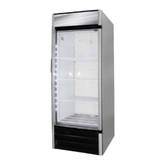
I. General Information A. Construction Illuminated sign Heavy duty hinges Forced-air evaporator for quick temperature pull down Exterior cabinet made of galvanized, pre-painted steel, with baked polyester paint Interior lighting LED lamp strip Reinforced heavy duty shelves NSF compliant interior cabinet Double-pane Low-E glass door for high ambient condition... -
Page 8: Refrigeration Circuit
B. Refrigeration Circuit... -
Page 9: Sequence Of Operation And Service Diagnosis
II. Sequence of Operation and Service Diagnosis A. Sequence Flow Chart 1. RM-7-HC, RM-10-HC, RM-26-HC, RM-49-HC, RM-65-HC... - Page 10 2. RM-7-HCB...
- Page 11 3. RM-45-SD-HC...
-
Page 12: Service Diagnosis
B. Service Diagnosis Risque De Feu Ou D'Explosion DANGER Le Frigorigène Est Inflammable Risk of Fire or Explosion • Suivre attentivement les instructions Flammable Refrigerant Used de manipulation conformément à la • Follow handling instructions carefully réglementation gouvernementale. in compliance with U.S. government •... - Page 13 The maximum allowable voltage variation is ±10 percent of the nameplate rating. 115VAC is used as a reference voltage when checking voltage to components. Voltage may vary depending on power supply. Factory Default Temperature Setpoint: RM-7-HC, RM-7-HCB, RM-10-HC, RM-26-HC, RM-49-HC, RM-65-HC 35°F (1.66°C) RM-45-SD-HC 35.6°F (2°C) Temperature Display Scale: °F (°C)
-
Page 14: Troubleshooting
1. Troubleshooting Check for correct appliance installation per the instruction manual and proper voltage per appliance nameplate. a) Not Cooling Not Cooling - Possible Cause 1. Power Supply a) Unplugged, off, blown fuse, tripped or defective circuit breaker. On three-section receptacle box, only top receptacles have power. - Page 15 b) Too Much Cooling Too much cooling - Possible Cause 1. Cabinet Thermistor a) Defective. c) Extreme Condensation Extreme condensation - Possible Cause 1. Cabinet Thermistor a) Loose. b) Installed improperly. 2. Door a) Door not shut completely (Defective gasket or hinges not adjusted).
- Page 16 g) Alarm Safeties 1. Sollatek control module LEDS Mains Voltage Compressor Description Off.Voltage bad (too high or too low). Wait period. (Intelligent Time Delay). Allows neutralisation of refrigerant pressure. On. Voltage good. No wait time. Cooling demand. Defrost Period. Starts after 6 hours of accumulated compressor run time for 25 minutes.
-
Page 17: Control Module Check
C. Control Module Check 1. RM-7-HC, RM-10-HC, RM-26-HC, RM-45-SD-HC, RM-49-HC, RM-65-HC Coel CT-198-CO control module 1. Control Module. Before replacing CM that does not show a visible defect and that you suspect is bad, conduct the following check procedure. This procedure will help you verify your diagnosis. -
Page 18: A) Thermistor Check
a) Thermistor Check The cabinet thermistor is used for cabinet temperature control. Thermistor resistance varies depending on temperature. The control module monitors the thermistors to control system operation. No adjustment is required. The defrost initiation occurs every 6 hrs. of cumulative compressor run time with a maximum duration of 25-min. -
Page 19: B) Temperature Setting Dial
b) Temperature Setting Dial 1. RM-7-HC, RM-10-HC, RM-26-HC, RM-45-SD-HC, RM-49-HC, RM-65-HC Coel CT-198-CO control module Marking 1 Cut-In/Cut-out: 47.0 39.0 Marking 2 Cut-In/Cut-out: 46.0 38.0 Marking 3 Cut-In/Cut-out: 45.0 37.0 Marking 4 Cut-In/Cut-out: 44.0 36.0 Marking 5 Cut-In/Cut-out: 43.0 35.0 Marking 6 Cut-In/Cut-out: 42.0 34.0... -
Page 20: Rm-7-Hcb
2. RM-7-HCB Carel CT-185-CA control module The temperatures programmed in your control module are indicated on the inside right wall of your unit. Energy saving mode selector To turn OFF the lights of the cooler press the light bulb symbol Energy saving device: 1. -
Page 21: Refrigeration Circuit And Component Service Information
III. Refrigeration Circuit and Component Service Information DANGER Risk of Fire or Explosion Flammable Refrigerant Used • Follow handling instructions carefully in compliance with U.S. government regulations. • Do not use mechanical devices to defrost. • Do not puncture refrigerant tubing. Risk of fire or explosion due to puncture of refrigerant tubing;... - Page 22 WARNING • Wear appropriate personal protective equipment (PPE) when servicing the appliance. • Technician must utilize a combustible gas leak detector at all times. • Notify everyone in the immediate area that you are working with flammable refrigerant. • Do not work on appliance in a confined space. Confirm area is well ventilated. •...
-
Page 23: Service For Refrigerant Lines
A. Service for Refrigerant Lines WARNING • Repairs requiring the refrigeration circuit to be opened must be performed by properly trained and EPA-certified service personnel. • Use an electronic leak detector or soap bubbles to check for leaks. Add a trace of refrigerant to the system (if using an electronic leak detector), and then raise the pressure using nitrogen gas (140 PSIG). -
Page 24: Brazing
2. Brazing DANGER Risk of Fire or Explosion Flammable Refrigerant Used • Servicing shall be done by factory authorized service personnel to minimize the risk of possible ignition due to incorrect parts or improper service. Risque De Feu Ou D'Explosion Le Frigorigène Est Inflammable •... -
Page 25: Evacuation
5) Disconnect the gauge manifold hose from the vacuum pump and attach it to a refrigerant service cylinder. Remember to loosen the connection and purge the air from the hose. For the required refrigerant charge, see the nameplate. Hoshizaki recommends only virgin or reclaimed refrigerant which meets ARI Standard 700 (latest edition) be used. -
Page 26: Maintenance
B. Maintenance WARNING • Unplug the appliance before performing maintenance to prevent electric shock or injury by moving parts. • Before performing maintenance, move all foods into another clean refrigerator or freezer. 1. Condenser Check the condenser once a year and use a brush or vacuum cleaner to clean the condenser as required. -
Page 27: Preparing The Appliance For Periods Of Non-Use
IV. Preparing the Appliance for Periods of Non-Use WARNING • When preparing the appliance for long storage, prevent the doors from closing to reduce the risk of children getting trapped. • To reduce the risk of electric shock, do not touch the attachment plug with damp hands. -
Page 28: Disposal
V. Disposal DANGER Risk of Fire or Explosion Flammable Refrigerant Used • Follow handling instructions carefully in compliance with U.S. government regulations. • Do not puncture refrigerant tubing. Risk of fire or explosion due to puncture of refrigerant tubing; follow handling instructions carefully. •... -
Page 29: Technical Information
See the nameplate for electrical and refrigerant data. The nameplate is located inside the cabinet. Electrical and Refrigerant Data Design Pressure (PSIG) Refrigerant (oz.) Model AC Supply Voltage Amperes HIGH R-290 RM-7-HC 115/60/1 RM-7-HCB 115/60/1 RM-10-HC 115/60/1 RM-26-HC 115/60/1 RM-45-SD-HC 115/60/1 RM-49-HC 115/60/1... -
Page 30: Wiring Diagrams
B. Wiring Diagrams 1. RM-7-HC Coel CT-198-CO control module Model Run Capacitor Starting Capacitor RM-7-HC 12 μF 180 V... - Page 31 2. RM-7-HCB Carel CT-185-CA control module Model Run Capacitor Starting Capacitor RM-7-HCB 12 μF 180 V...
- Page 32 3. RM-10-HC Coel CT-198-CO control module Model Run Capacitor Starting Capacitor RM-10-HC 10 μF 250 V 125 μF 160 V...
- Page 33 4. RM-26-HC Coel CT-198-CO control module Model Run Capacitor Starting Capacitor RM-26-HC 20 μF 180 V...
- Page 34 5. RM-45-SD-HC Coel CT-198-CO control module Model Run Capacitor Starting Capacitor RM-45-SD-HC 10 μF 250 V 150 μF 160 V...
- Page 35 6. RM-49-HC Coel CT-198-CO control module Model Run Capacitor Starting Capacitor RM-49-HC 10 μF 250 V 150 μF 160 V...
- Page 36 7. RM-65-HC Coel CT-198-CO control module Model Run Capacitor Starting Capacitor RM-65-HC 20 μF 180 V...
Need help?
Do you have a question about the RM-7-HCB and is the answer not in the manual?
Questions and answers