Table of Contents
Advertisement
Quick Links
Description ................................. 5
Installation ............................... 12
Start-Up ................................... 22
Troubleshooting ....................... 23
Maintenance ............................. 26
Warranty .................................. 27
Start-Up Checklist .................... 28
Appendix B Reverse Flow w/Economizer
Exhaust Hood Installation ....... 34
Installation ............................... 35
Controller ................................. 36
Industrial Climate Engineering™, An AirX Climate Solutions Brand
E-mail: icesales@airxcs.com • Internet: www.acice.com
The most current version of this manual can be found at www.acice.com.
Installation & Operation Manual
CFA3240A/3300A/3360A
Manufactured By:
P.O. Box 5104 • Cordele, Georgia 31010
2002 Hoover St. • Cordele, Georgia 31015
(229) 273-9558 • Fax (229) 273-5154
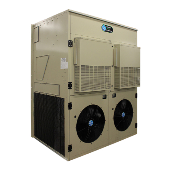
Vertical Air Conditioners
CFA3240A w/Economizer
ICE CFA3240A-3300A-3360A I&O Manual 10/2023 Rev.11
Advertisement
Chapters
Table of Contents
Troubleshooting

Related Manuals for ACS ICE CFA3240A


Summary of Contents for ACS ICE CFA3240A
-
Page 1: Table Of Contents
P.O. Box 5104 • Cordele, Georgia 31010 2002 Hoover St. • Cordele, Georgia 31015 (229) 273-9558 • Fax (229) 273-5154 E-mail: icesales@airxcs.com • Internet: www.acice.com The most current version of this manual can be found at www.acice.com. ICE CFA3240A-3300A-3360A I&O Manual 10/2023 Rev.11... - Page 2 Failure to comply could result in minor personal injury and/or property damage. CAUTION Used to point out helpful info that will result in improved installation, reliability or operation. IMPORTANT SPECIFICATIONS SUBJECT TO CHANGE WITHOUT NOTICE. © 10/2023 Industrial Climate Engineering™, An AirX Climate Solutions Brand ICE CFA3240A-3300A-3360A I&O Manual 10/2023 Rev.11...
- Page 3 Installing the Lifting Brackets ........................16 Mounting the Unit ..........................16 Compressor Chocks Removal ........................17 Unit Support Recommendations ......................18 2.10 Electrical Connections ...........................18 Chapter 3 Start-Up Check-Out of Cooling Cycle .........................22 Check-Out of Heating Cycle ........................22 ICE CFA3240A-3300A-3360A I&O Manual 10/2023 Rev.11...
- Page 4 Cooling Performance and Air Flow .................... 7 Table 2 Filter Sizes/Part Numbers ......................7 Table 3 Shipping Weights & Dimensions ....................7 Table 4 Refrigerant Charge ........................7 Table 5 Minimum Clearances ........................ 13 Table 6 Voltage Limitations ........................13 ICE CFA3240A-3300A-3360A I&O Manual 10/2023 Rev.11...
-
Page 5: Chapter 1 Description
ICE CFA units are designed for easy installation and service. Major components are accessible for service beneath external panels. All units have internal disconnects. Depending upon state and local code requirements, this feature may eliminate the need for an external breaker or disconnect. ICE CFA3240A-3300A-3360A I&O Manual 10/2023 Rev.11... -
Page 6: Model Identification
Note: Follow local codes and standards when designing duct runs to deliver the required airflow. Minimize noise and excessive pressure drops caused by duct aspect ratio changes, bends, dampers and outlet grilles in duct runs. ICE CFA3240A-3300A-3360A I&O Manual 10/2023 Rev.11... -
Page 7: General Operation
Cold liquid refrigerant passing through the evaporator is boiled into gas by heat removed from the air. The warmed refrigerant gas enters the compressor where its temperature and pressure are increased. The hot refrigerant gas condenses to liquid as heat is transferred to outdoor air ICE CFA3240A-3300A-3360A I&O Manual 10/2023 Rev.11... -
Page 8: Optional Controls And Packages
On a call for heat, the thermostat closes the heat relay to energize the indoor fan and the resistance elements. Optional Controls & Packages Protective Coating Packages Coated Coils: Either the condenser or evaporator coil can be coated. For harsh conditions, e.g., ICE CFA3240A-3300A-3360A I&O Manual 10/2023 Rev.11... -
Page 9: Electrical Operation
Power must be applied to the unit for 24 hours before starting the compressor. The condenser (outside fan) motor is energized by the same contactor. The indoor evaporator fan motor is controlled by the fan purge on the electronic control board. ICE CFA3240A-3300A-3360A I&O Manual 10/2023 Rev.11... -
Page 10: Figure 1A. Typical Electrical Schematics For Single Compressor Units
Figure 1a. Typical Electrical Schematic for Single Compressor Units ICE CFA3240A-3300A-3360A I&O Manual 10/2023 Rev.11... -
Page 11: Figure 1B. Typical Electrical Schematics For Dual Compressor Units
Figure 1b. Typical Electrical Schematic for Dual Compressor Units ICE CFA3240A-3300A-3360A I&O Manual 10/2023 Rev.11... -
Page 12: Chapter 2 Installation
C) The unit exhausts air. Be sure that the airflow is not impeded by shrubbery or other obstructions. D) When installing multiple units, please note the recommended clearances noted in Table 4. CAUTION CFA3240, 3300, 3360 units require additional support. The mounting flanges alone are not adequate. ICE CFA3240A-3300A-3360A I&O Manual 10/2023 Rev.11... -
Page 13: Installation Materials
The bracket is shipped attached to the top of the unit. Before installing the unit, remove the bracket and reattach as described in Section 2.5 ICE CFA3240A-3300A-3360A I&O Manual 10/2023 Rev.11... - Page 14 • High voltage wire, sized to handle the MCA (minimum circuit ampacity) listed on the data plate. • Over-Current Protection Device sized in accordance with the MFS (maximum fuse size) listed on the unit data plate. ICE CFA3240A-3300A-3360A I&O Manual 10/2023 Rev.11...
-
Page 15: Porting And Duct Work
Remove the 4 screws in these holes and use these screws to attach the top flange to the air conditioner. 3. Apply a bead of silicone sealer on the wall side of the bottom support brackets on the unit. Circle the mounting holes with the silicone bead. ICE CFA3240A-3300A-3360A I&O Manual 10/2023 Rev.11... -
Page 16: Installing The Lifting Brackets
7. Check the fit of each sleeve to its mating flange for possible air leaks. Apply silicone sealer to close any gaps. Install the air return and supply grilles. ICE CFA3240A-3300A-3360A I&O Manual 10/2023 Rev.11... -
Page 17: Compressor Chocks Removal
Note: There are two chocks to be removed one in the front of the compressor and one at the back of the compressor. Screw Rear Chock Front Chock Figure 4. Compressor Chock Removal ICE CFA3240A-3300A-3360A I&O Manual 10/2023 Rev.11... -
Page 18: Unit Support Recommendations
Verification of proper rotation is made by observing ICE CFA3240A-3300A-3360A I&O Manual 10/2023 Rev.11... - Page 19 Insulate the orange lead. CAUTION The external breaker(s) that provide power to the air conditioner must be sized per the maximum Fuse Size (MFS) shown on the Unit's data label. ICE CFA3240A-3300A-3360A I&O Manual 10/2023 Rev.11...
- Page 20 CommStat Touch Lead/Lag HVAC Controller (See Figure 4b) The CommStat Touch telecom controller with a touch screen interface is designed to allow remote control and monitoring of ICE air conditioners with single or 2-stage compressors in a shelter ICE CFA3240A-3300A-3360A I&O Manual 10/2023 Rev.11...
- Page 21 HVAC configuration. See the CommStat Touch PDS for more details. ICE SIMPLE COMFORT THERMOSTAT CONNECTION DIAGRAM Figure 6. Thermostat Connection Diagram ICE CFA3240A-3300A-3360A I&O Manual 10/2023 Rev.11...
-
Page 22: Chapter 3 Start-Up
1. Raise the heating set point temperature to a setting which is higher than the ambient temperature. The fan and electric heat should immediately cycle on. 2. Move the system switch to the "OFF" position. All functions should stop. ICE CFA3240A-3300A-3360A I&O Manual 10/2023 Rev.11... -
Page 23: Chapter 4 Troubleshooting
Use refrigeration goggles when servicing the refrigeration circuit. WARNING The refrigerant circuit has hot surfaces, and the electrical voltages inside of the unit may be hazardous or lethal. SERVICE MAY BE PERFORMED ONLY BY QUALIFIED AND EXPERIENCED PERSONS. ICE CFA3240A-3300A-3360A I&O Manual 10/2023 Rev.11... -
Page 24: Failure Symptoms Guide
NOTE: It is important to rule out other component failures before condemning the compressor. The following electrical tests will aid diagnosis: 1. Start-Up Voltage: Measure the voltage at the compressor contactor during start-up. The voltage ICE CFA3240A-3300A-3360A I&O Manual 10/2023 Rev.11... -
Page 25: Control Board Diagnosis
The unit must be in the cooling mode (compressor contactor Closed) before a fault condition can occur. ICE CFA3240A-3300A-3360A I&O Manual 10/2023 Rev.11... -
Page 26: Chapter 5 Maintenance
Some solvents can cause the drain pan to corrode. Lubrication The condenser fan motor(s) and the evaporator blower motor(s) never require oiling. ICE CFA3240A-3300A-3360A I&O Manual 10/2023 Rev.11... -
Page 27: Chapter 6 Warranty
THIS WARRANTY GIVES YOU SPECIFIC LEGAL RIGHTS, AND YOU MAY ALSO HAVE OTHER RIGHTS WHICH VARY FROM STATE-TO- STATE. Some states do not allow limitations or exclusions, so the above limitations and exclusions may not apply to you. ICE CFA3240A-3300A-3360A I&O Manual 10/2023 Rev.11... -
Page 28: Chapter 7 Start-Up Checklist
Are all wiring terminals (including main power supply) tight? ❒Yes ❒No If unit has a crankcase heater, has it been energized for 24 hours? ❒Yes ❒No On a 208/230 v. units is control transformer (24 AC) wired for correct voltage? ❒Yes ❒No ICE CFA3240A-3300A-3360A I&O Manual 10/2023 Rev.11... - Page 29 L1 & L3 = 243 Volts = 717 / 3 = 239 Average Voltage L2 & L3 = 233 Volts 239 - 233 = 6 100 x 6/239 =2.5% Voltage Unbalance Three phase units only check fan & compressor rotation. ICE CFA3240A-3300A-3360A I&O Manual 10/2023 Rev.11...
- Page 30 Measured Line to Line Volts L1&L2_______V. L1&L3 ________V. L2&L3______V. (L1&L2 + L1&L3 + L2&L3)/3 = Avg. Voltage = _______________ Max. Deviation from avg. voltage = ______________volts Voltage imbalance = (100 x Max. Deviation)/avg. Voltage = ___________% ICE CFA3240A-3300A-3360A I&O Manual 10/2023 Rev.11...
- Page 31 Evap. Leaving Air WB Temp ________ ________ Compressor Amps (L1) ________ ________ Compressor Amps (L2) ________ ________ Compressor Amps (L3) ________ ________ Notes: _________________________________________________________________________ _________________________________________________________________________ _________________________________________________________________________ _________________________________________________________________________ _________________________________________________________________________ _________________________________________________________________________ _________________________________________________________________________ _________________________________________________________________________ _________________________________________________________________________ _________________________________________________________________________ _________________________________________________________________________ _________________________________________________________________________ ICE CFA3240A-3300A-3360A I&O Manual 10/2023 Rev.11...
-
Page 32: Appendix A Fresh Air Damper Installation
Appendix A Fresh Air Damper Installation ICE CFA3240A-3300A-3360A I&O Manual 10/2023 Rev.11... - Page 33 15% of rated air flow of fresh air, in 5% increments. The hood is shipped from the factory in the closed position (no fresh air). To provide fresh air, remove the two screws on either side of the hood and reposition as desired. Fresh Air Hood Damper ICE CFA3240A-3300A-3360A I&O Manual 10/2023 Rev.11...
-
Page 34: Exhaust Hood Installation
C. ALIGN HOLES IN THE HOOD ASSY FLANGES WITH PREDRILLED HOLES IN THE TOP PANEL OF UNIT (ITEM 2 ) D. SCREW INTO PLACE WITH SHEET METAL SCREWS PROVIDED E. ADD SILICONE BEAD AROUND THE TWO SIDES AND REAR OF THE HOOD ASSY ICE CFA3240A-3300A-3360A I&O Manual 10/2023 Rev.11... -
Page 35: Appendix C Optional Condenser Filter Installation
Division of AIRXCEL, Inc. Cordele, GA FILTER FRAME DECIMAL SCALE DRAWN BY .03" ± APPROVED BY FRACTIONAL TITLE ± ANGULAR DATE DRAWING NUMBER 3090-3360 CONDENSER 2018-12-17 REV. ± FILTER ASSY Appendix A COIL GUARD ICE CFA3240A-3300A-3360A I&O Manual 10/2023 Rev.11... -
Page 36: Appendix D Dpc200 Differential Pressure Controller
Appendix D DPC200 Differential Pressure Controller Installation and operation manual DPC200 - DIFFERENTIAL PRESSURE CONTROLLER Low pressure with PI-control-mode Doc.-no.: DPC200_01_EBM_UK Issue: 12/2015 ICE CFA3240A-3300A-3360A I&O Manual 10/2023 Rev.11... - Page 37 Arthur Grillo GmbH. This applies in particular to duplications, trans- lations, microfilming and storage and processing in electronic systems. Doc.-no.: DPC200_01_EBM_UK Issue: 12/2015 ICE CFA3240A-3300A-3360A I&O Manual 10/2023 Rev.11...
- Page 38 Schematic view inside Pressure connections Electrical connection Zero adjustment Operation Start menu Menu structure Measuring mode Control mode Adjustable parameters Function alarm output Maintenance Warranty Troubleshooting Disposal Specifications 10.1 CE-labelling Ordering information Doc.-no.: DPC200_01_EBM_UK Issue: 12/2015 ICE CFA3240A-3300A-3360A I&O Manual 10/2023 Rev.11...
-
Page 39: General Safety Instructions
This manual contains information for installation and operation of the pressure controller and is exclusively for the operator and ex- pert staff. The guidelines in this manual will help to avoid danger and downtime. Doc.-no.: DPC200_01_EBM_UK Issue: 12/2015 ICE CFA3240A-3300A-3360A I&O Manual 10/2023 Rev.11... -
Page 40: Product Description
0...10 V DC output signal. Instead of the quantity ‘differential pressure’ also the quantity ‘volume flow’ can be used for measuring and for control. Doc.-no.: DPC200_01_EBM_UK Issue: 12/2015 ICE CFA3240A-3300A-3360A I&O Manual 10/2023 Rev.11... -
Page 41: Installation
3.2 Wall mounting Hold the DPC200 against the wall. Mark the mounting holes. Drill mounting holes for properly sized screws. Put the screws through the housing mounting holes. Tighten screws. Doc.-no.: DPC200_01_EBM_UK Issue: 12/2015 ICE CFA3240A-3300A-3360A I&O Manual 10/2023 Rev.11... -
Page 42: Start Up
Button T1 Button T2 Button T1 and T2 serve for the operation of the menu 4.3 Pressure connections Connect all pressure connections properly with plastic tubing (inner diameter 5 or 6mm). Doc.-no.: DPC200_01_EBM_UK Issue: 12/2015 ICE CFA3240A-3300A-3360A I&O Manual 10/2023 Rev.11... -
Page 43: Electrical Connection
+ Versorgung: 10...30 Vdc; ∆P 24 Vac +/-15% Operation - GND + Ausgang 0...10 V 5.1 Start menu For operating the menu, unscrew the front cover to reach buttons T1 and T2. Doc.-no.: DPC200_01_EBM_UK Issue: 12/2015 ICE CFA3240A-3300A-3360A I&O Manual 10/2023 Rev.11... -
Page 44: Menu Structure
OPERATION Menu Operation 5.2 Menu structure Doc.-no.: DPC200_01_EBM_UK Issue: 12/2015 ICE CFA3240A-3300A-3360A I&O Manual 10/2023 Rev.11... -
Page 45: Measuring Mode
Button T1: confirm value, display flashes once Press button T2 to get to the next menu item Press button T1 to leave the menu back and confirm Press button T2 to stay in the menu Doc.-no.: DPC200_01_EBM_UK Issue: 12/2015 ICE CFA3240A-3300A-3360A I&O Manual 10/2023 Rev.11... -
Page 46: Control Mode
/ heating <=> negative / cooling positive / heating Press button T2 to go to the next menu Press button T1 to leave the menu back and confirm Press button T2 to stay in the menu Doc.-no.: DPC200_01_EBM_UK Issue: 12/2015 ICE CFA3240A-3300A-3360A I&O Manual 10/2023 Rev.11... -
Page 47: Adjustable Parameters
The output increases when set value > actual value. Control characteri- positive / heating negative/(cooling): Control deviation = actual value – set value stic: The output increases when actual value > set value Doc.-no.: DPC200_01_EBM_UK Issue: 12/2015 ICE CFA3240A-3300A-3360A I&O Manual 10/2023 Rev.11... -
Page 48: Function Alarm Output
In the default setting the limits are not active. Display 2nd line: „OFF“ Alarm ON: Measurement for 12 seconds constantly greater than 1.0 • limit value Alarm OFF: Measurement for 12 seconds constantly less than 0.95 • limit value Doc.-no.: DPC200_01_EBM_UK Issue: 12/2015 ICE CFA3240A-3300A-3360A I&O Manual 10/2023 Rev.11... -
Page 49: Maintenance
Dispose of parts so as not to endanger human health or the environment. Follow the laws in the country of use for disposing of electronic components and devices during disposal. Doc.-no.: DPC200_01_EBM_UK Issue: 12/2015 ICE CFA3240A-3300A-3360A I&O Manual 10/2023 Rev.11... -
Page 50: Specifications
(depends on measuring range): ± 0.5 % ... ± 1 % Temperature drift, zero point: ± 0.3 % / 10 K Temperature drift, span: ± 0.2 % / 10 K Doc.-no.: DPC200_01_EBM_UK Issue: 12/2015 ICE CFA3240A-3300A-3360A I&O Manual 10/2023 Rev.11... -
Page 51: Ce-Labelling
Differential pressure controller DPC200 2576 Measurement range: 0...2000 Pa Differential pressure controller DPC200 2578 Measurement range: 0...4000 Pa Mounting set M-DS 25110 with screws, bleeders and 2m plastic tube (4 x 1,5 mm) Doc.-no.: DPC200_01_EBM_UK Issue: 12/2015 ICE CFA3240A-3300A-3360A I&O Manual 10/2023 Rev.11...
Need help?
Do you have a question about the ICE CFA3240A and is the answer not in the manual?
Questions and answers