Table of Contents
Advertisement
Quick Links
Installation & Operation Manual
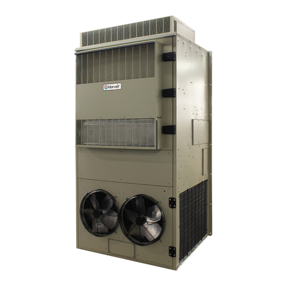
7.5, 10, 12.5 & 15 Ton 10EER Vertical
Wall Mount Air Conditioners
Installation & Operation Manual
10 EER Vertical Wall-Mount Air Conditioners
MODELS:
MGA3090A • MGA3120A
MGA3150A • MGA3180
(Dual Compressor)
IMPORTANT
This manual may include information for options and features which may not be
included on the unit being installed. Refer to the unit data label or Model Identification
to determine which features and options this unit is equipped with.
INSTALLER: Affix the instructions on the inside of the building adjacent to the thermostat.
END USER: Retain this manual for future reference.
Manufactured By:
Marvair, An ACS Brand
P.O. Box 400 • Cordele, Georgia 31010 • 156 Seedling Drive • Cordele, Georgia 31015
(229) 273-3636 • Fax (229) 273-5154
www.Marvair.com
The most current version of this manual can be found at www.Marvair.com.
Marvair MGA3090-3180 Wall Mount AC I&O Manual 05/2023 Rev.14
Advertisement
Table of Contents
Troubleshooting

Related Manuals for ACS Marviar MGA3090A


Summary of Contents for ACS Marviar MGA3090A
- Page 1 INSTALLER: Affix the instructions on the inside of the building adjacent to the thermostat. END USER: Retain this manual for future reference. Manufactured By: Marvair, An ACS Brand P.O. Box 400 • Cordele, Georgia 31010 • 156 Seedling Drive • Cordele, Georgia 31015 (229) 273-3636 • Fax (229) 273-5154 www.Marvair.com...
- Page 2 Failure to comply could result in minor personal injury and/or property damage. CAUTION Used to point out helpful info that will result in improved installation, reliability or operation. IMPORTANT SPECIFICATIONS SUBJECT TO CHANGE WITHOUT NOTICE. © 04/2023 Marvair, An ACS Brand Marvair MGA3090-3180 Wall Mount AC I&O Manual 05/2023 Rev.14...
-
Page 3: Table Of Contents
WARNING • If the information in these instructions are not followed exactly, a fire may result causing property damage, personal injury or loss of life. • Read all instructions carefully prior to beginning the installation. Do not begin installation if you do not understand any of the instructions. •... - Page 4 Chapter 5 Troubleshooting Overview ..............................43 Failure Symptoms Guide ........................44 Compressor Troubleshooting .........................44 Chapter 6 Maintenance Scheduled Maintenance .........................46 Chapter 7 Warranty Limited Product Warranty ........................47 Chapter 8 Start-Up Check List Start-Up Check List ..........................48 Illustrations Figure 1. PLC ............................10 Figure 2. Typical Electrical Schematic ......................15 Figure 3.
-
Page 5: General Description
Chapter 1 Description & Specifications General Description The Marvair MGA3090A, MGA3120A, MGA3150A & MGA3180A are a series of vertical wall- mounted air conditioning systems that provide heating, cooling, and ventilation for telecommunication shelters, and other applications with high internal heat gains. The series is available in nominal cooling capacities of 90,000-180,000 BTUH. -
Page 6: Model Identification
Model Identification The model identification number is found on the data sticker. Rating plate located on side panel. Example Position Unit Designation/Family M = Marvair Wall Mount D = Dry Bulb Sensor Indoor Air Quality E = Dry Bulb Sensor w/Dirty Filter Energy Efficiency Ratio (EER) G = 10 Features G = Dirty Filter Sensor... -
Page 7: Table 1 Efficiency And Capacity Ratings At Ansi/Ahri Standard 390
Note: Follow local codes and standards when designing duct runs to deliver the required airflow. Minimize noise and excessive pressure drops caused by duct aspect ratio changes, bends, dampers and outlet grilles in duct runs. Model Number Cooling BTUH Rated Air Flow (CFM) MGA3090A 89,000 3,500... -
Page 8: Table 4 Dual Compressor Cooling Performance (Btuh) At Various Outdoor Temperatures
Outdoor Temperature Return Air Model Cooling DB/WB 75°F 80°F 85°F 90°F 95°F 100°F 105°F 110°F 115°F 120°F 125°F 130°F Number Capacity °F (°C) (24°C) (27°C) (30°C) (32°C) (35°C) (38°C) (41°C) (43°C) (46°C) (49°C) (52°C) (54°C) BTUH 72/61 Total 92,382 89,178 86,063 82,859 79,655 76,451 73,247 70,132 68,530 66,928 65,326 63,724 (22/16) Sensible 68,795 67,490 66,228 64,938 63,655 62,379 61,110 59,883 59,255 58,629 58,004 57,381... -
Page 9: Table 7 Shipping Weights & Dimensions
Shipping Dimensions Unit Weight Shipping Weight Model Height Width Depth Inches Inches Inches MGA3090A 1,085 1,160 2,489 1,422 1,219 MGA3090A Reverse Flow 1,085 1,160 2,489 1,422 1,219 MGA3090A Reverse Flow w/Economizer 1,131 1,210 2,489 1,422 1,219 MGA3120A 1,195 1,277 2,489 1,422 1,219 MGA3120A Reverse Flow... -
Page 10: General Operation
General Operation Optional Hot Gas By-Pass Normally used in specialty applications (i.e Magnetic Resonance Imaging (MRI) buildings) to prevent magnetic voltage disturbance caused by cycling. This technology is applied in this product to extend the operation envelope for the compressor to 20º F (-6.6ºC). Combined with a condenser low ambient Fan Cycle feature, compressor operation can be extended to 0º... - Page 11 PLC Inputs & Outputs The PLC has inputs located along the top right of the controller and outputs along the bottom right of the controller. An input is a signal to the PLC from either the thermostat, sensors in the air conditioner, or a customer supplied input, e.g., EMS (Energy Management System).
-
Page 12: 1.7 Unit Operation
3. MAINT – (Maintenance) flashes whenever you insert a memory card. The CPU then changes to STOP mode. After the CPU has changed to STOP mode, perform one of the following functions to initiate the evaluation of the memory card: a. -
Page 13: Optional Controls And Packages
PLC Flash Code for Lockout Indicator Number of Flashes Description of Fault High pressure switch A fault Low pressure switch A fault High pressure switch B fault Low pressure switch B fault Phase fault Heater current overload fault Emergencey Management System fault •... -
Page 14: 1.9 Electrical Operation
1.9 Electrical Operation The compressor and condenser fan are energized with a contactor controlled by a 24 VAC pilot signal. Some compressors incorporate an internal PTC crankcase heater that functions as long as primary power is available. The heater drives liquid refrigerant from the crankcase and prevents loss of lubrication caused by oil dilution. -
Page 15: Figure 2. Typical Electrical Schematic
Figure 2. Typical Electrical Schematic Marvair MGA3090-3180 Wall Mount AC I&O Manual 05/2023 Rev.14... -
Page 16: Chapter 2 Electronic Control Board
Chapter 2 Electronic Control Board Introduction WARNING Failure to observe the instructions contained in this document may result in personal injury and/or property damage and may void the warranty. Read this manual before installing, replacing or using this product. Marvair’s proprietary Printed Circuit Board (PCB) sets the standard for the industry in flexibility, reliability and performance. -
Page 17: Installation And Replacement
Item Description Economizer Actuator Output 2-10 VDC Outdoor Motor Control Output 0-10 VDC or PWM Indoor Motor Control Output 0-10 VDC or PWM Enthalpy Sensor Signal Input 4-20mA Outdoor Sensor Signal 10K NTC (Heat Pumps) / Dry Bulb Sensor Signal Input 10K NTC (Systems Equipped with Dry Bulb Economizer) Supply Air Sensor Signal Input 10K NTC (Systems Equipped with Economizer) Defrost Sensor Signal Input 10k NTC (Heat Pumps Only) - Page 18 2.3.1 – Programming Menu Configuration 1. To Enter Programming Mode: • Press and hold the Menu button for 5 seconds until P-01 is displayed. 2. While in Programming Mode main menu: • Press the Menu button to enter the displayed parameter menu. •...
- Page 19 Configuration Menu Details 1. AC/HP Select: This setting allows the PCB to be configured for AC (air-conditioner) or HP (heat- pump). The system type is configured at the factory during production testing for the appropriate system type. The default system type is AC. 2.
- Page 20 for W2 (auxiliary / emergency heat). When the SCKT Set is set to Y (yes) the electric heat will not be allowed to operate with the compressor in the heat-pump mode. When set to Y (yes) and upon a request for W2 (auxiliary / emergency heat) the compressor will shut off and the electric heat will operate.
-
Page 21: Sequence Of Operation
the Dehum speed is 80% of maximum speed. The speed may be adjusted from 60-100% in 1% increments to meet desired airflow requirements. 18. DS Calibration: This setting is used to calibrate the defrost sensor from 0 to -18F. 19. SAS Calibration: This setting is used to calibrate the supply air sensor from 0 to -18F. 20. - Page 22 1.0 Indoor Blower Operation 1.1 G - Indoor Blower Only 1.2 Y1 - Indoor Blower Operation 1.3 Y2 - Indoor Blower Operation 1.4 W2 – Indoor Blower Operation 1.5 HUM – Indoor Blower Operation 2.0 Cooling Operation AC / HP 2.1 Mechanical Cooling (AC systems) 2.1.1 Partial Capacity 2.1.2 Full Capacity...
- Page 23 1.0 Indoor Blower Operation The speed at which the indoor blower will operate is based on the discrete operational inputs that have 24vac applied. These inputs are listed below. 1.1 G Input – A request for Fan Only (independent G-signal via Digital input or Modbus), results in the indoor motor turning “ON”...
- Page 24 2.1 Mechanical Cooling (AC systems) – This section will describe the sequence of operation which takes place during Direct Expansion (DX) cooling from a control standpoint. Note: The system type must be configured for “AC” operation in setting 1 of the configuration menu of the control board for proper AC system operation.
- Page 25 to the “Y1” speed setting on the board or via Modbus. It also outputs a request dependent (based on FCC IN) control signal for the Outdoor Fan Motor (Only applicable to ECM motors). In Stage 1 Cooling operation, the compressor operates at partial capacity and the indoor fan remains on continuously but the outdoor fan modulates based on liquid line temperature.
-
Page 26: Figure 3. Enthalpy Sensor & Temperature Control Points
Enthalpy Setpoint is Setting 14 in control board configuration menu. Options A= 73ºF B= 70ºF C= 67ºF D= 63ºF E= 55ºF All settings are @ 50%Rh Figure 3. Enthalpy Sensor & Temperature Control Points Enthalpy Operation On a call for cooling from the wall-mounted thermostat, if outdoor conditions are suitable, the sensor will open the damper and admit outside air (i.e., economizer free cooling). -
Page 27: Figure 4. Dry Bulb Sensor
Figure 4. Dry Bulb Sensor On a call for cooling from the wall-mounted thermostat, if outdoor conditions are suitable, the sensor will open the damper and admit outside air (i.e., economizer free cooling). If the outdoor ambient is too hot (dry bulb sensor only), the sensor will place the actuator in the closed or minimum open position and activate mechanical cooling. - Page 28 on the fan purge timer setpoint (default 90 seconds) selected in setting 3 of the configuration menu of the control board. Note: A request for Cooling and Heating at the same time is not allowed and control board will not allow the electric heat to operate. 4.2 Heat Pump Heating Operation –...
- Page 29 the heating setpoint is satisfied, the Indoor motor continues to run based on the fan purge timer setpoint (default 90 seconds) selected in setting 3 of the configuration menu of the control board. When the system is operating in Heap Pump mode the electric heat is considered as supplemental heat and will only be allowed under certain conditions due to additional features that may be used.
- Page 30 set on the control board for setting 7 in the configuration menu. The outdoor fan will speed up and slow down between liquid line temperature of 80F and 115F. Systems with (PSC Outdoor Motors) utilizes a Fan Cycle Switch which closes at 400 PSIG to energize the OFR (outdoor fan relay) to start the outdoor fan which runs until the switch reopens (at 290 PSIG).
- Page 31 The sensor is secured to the common suction line of the system to monitor the suction line temperature. This condition describes the abnormal fall in Suction Line Temperature below 9ºF. This fault will only be active when the Low-Pressure Sensor detects suction line temperatures below 9ºF during a request for Cooling / Heat pump heating.
- Page 32 10vdc signal from the ECO output of the control board to drive the motorized damper fully open. Note: The compressor and electric heat WILL NOT operate while in the emergency ventilation mode. 7.3 Forced Cooling (economizer equipped systems) – During economizer cooling, if a request for “Forced Cooling”...
-
Page 33: Chapter 3 Installation
Chapter 3 Installation WARNING Failure to observe and follow Warnings and Cautions and these Instructions could result in death, bodily injury or property damage. Read this manual and follow its instructions and adhere to all Cautions and Warnings in the manual and on the unit. Equipment Inspection Concealed Damage Inspect all cartons and packages upon receipt for damage in transit Remove cartons and check for... -
Page 34: Installation Materials
Duct work should be designed and installed in accordance with all applicable safety codes and standards. Marvair strongly recommends referring to the current edition of the National Fire Pro- tection Association Standards 90A and 90B before designing and installing duct work. The duct system must be engineered to insure sufficient air flow through the unit to prevent over-heating of the heater element. - Page 35 Accessories: The package may include other factory-supplied items (optional): Description S/07846 CommStat 4 HVAC Controller, Solid State Lead/Lag Controller K/40167 CommStat 10 HVAC Controller 50123 Digital thermostat. 1 stage heat, 1 stage cool. 7 day programmable. Fan switch: Auto & On.
-
Page 36: Porting And Duct Work
Porting and Duct Work General Information Note: The following instructions are for general guidance only. Due to the wide variety of installation possibilities, specific instructions will not be given. When in doubt, follow standard and accepted installation practices, or contact Marvair for additional assistance. -
Page 37: Installing The Lifting Brackets
3. Apply a bead of silicone sealer on the wall side of the bottom support brackets on the unit. Circle the mounting holes with the silicone bead. Figure 5 Top Flange and Lifting Bracket Installation (Typical) Installing the Optional Lifting Brackets Lifting brackets are available which can be installed on the top of the side panels. -
Page 38: Electrical Connections
For units with electric heat, a one inch clearance is required around the duct extensions. The duct extensions must be constructed of galvanized steel with a minimum thickness of .019” as per the NFPA standards 90A & 90B. Figure 6 Air Conditioner Wall Mount Detail Electrical Connections WARNING ELECTRICAL SHOCK HAZARD Failure to follow safety warnings exactly could result in serious injury, death, and/or... - Page 39 the installation of gauges may be objectionable, can be made by monitoring the temperature of the refrigerant lines at the compressor. The temperature should rise on the discharge line while the suction line temperature decreases. Reverse rotation also results in a substantially reduced current draw when compared to tabulated values.
-
Page 40: Figure 7A. Humidistat Wiring To A Marvair Air Conditioner With Reheat
Dual Unit Phasing For applications where one controller operates two units, e.g., the CommStat 4. 1. Wire each unit as described in steps 1 through 4 above. 2. Test for proper phasing as follows: A. Power up the units. B. Using an AC volt meter set to the 300 volt scale, measure voltage between terminal L1 on the compressor contactor of unit #1 and terminal L1 on the compressor contactor of unit #2 If voltage is present, units are wired out of phase and must be rewired. -
Page 41: Figure 7B. Thermostat Connection Diagram
Figure 7b. Thermostat Connection Diagram , t l " l " 2 n i l n i l n i l " l " 2 " l " R l i t . t l A " " 1 A " "... -
Page 42: Chapter 4 Start-Up
Chapter 4 Start-Up Check-Out of Cooling Cycle Important: Be sure that the crankcase heater (if used) has been energized for at least 24 hours before starting the unit(s). Double-check all electrical connections before applying power. All air conditioners with scroll compressors running on 3Ø power must be checked for proper rotation during the initial start-up. -
Page 43: Chapter 5 Troubleshooting
Chapter 5 Troubleshooting Overview The middle front panel provides access to the electrical/control box and to the filters. This panel has hinges on the left and right hand side. This panel should ONLY be opened by using the two hinges on the left side OR the two hinges on the right side. -
Page 44: Failure Symptoms Guide
Failure Symptoms Guide PROBLEM/SYMPTOM LIKELY CAUSE(S) CORRECTION A. Unit does not run. 1. Power supply problem. 1. Check power supply for adequate phase and voltage. Check wiring to unit and external breakers or fuses. NOTE: An internal anti-short-cycle 2. Tripped internal disconnect. 2. - Page 45 1. Start-Up Voltage: Measure the voltage at the compressor contactor during start-up. The voltage must exceed the minimum shown in Table 5, section 2.2, or compressor failure is likely. A low voltage condition must be corrected. 2. Running Amperage: Connect a clip-on type ammeter to the (common) lead to the compressor. Turn on the supply voltage and energize the unit.
-
Page 46: Chapter 6 Maintenance
Chapter 6 Maintenance The middle front panel provides access to the electrical/control box and to the filters. This panel has hinges on the left and right hand side. This panel should ONLY be opened by using the two hinges on the left side OR the two hinges on the right side. -
Page 47: Chapter 7 Warranty
Chapter 7 Warranty Marvair, Inc. Limited Product Warranty Marvair Inc., warrants its products to be free from defects in materials and workmanship under normal use to the original purchaser for the period of time in the table below. If any part of your product fails within 12 months from start-up, or 18 months from shipment from the factory, whichever comes first, Marvair, Inc. -
Page 48: Start-Up Check List
Chapter 8 Start-Up Check List The middle front panel provides access to the electrical/control box and to the filters. This panel has hinges on the left and right hand side. This panel should ONLY be opened by using the two hinges on the left side OR the two hinges on the right side. - Page 49 Condensate Section Has water been placed in drain pan to confirm proper drainage? ❒Yes ❒No Are correct filters in place? ❒Yes ❒No Refrigerant Piping If leaks are found, report any leaks to Marvair Warranty Service Dept. C. Check Rated Voltage at Terminal Block for Imbalance before starting of Unit. ❒208/230V 1 Phase ❒208/230V 3 Phase ❒460V 3 Phase...
- Page 50 D. Heating Mode Check & Record Readings Circuit 1 Circuit 2 (if applicable) Room Temperature ________ ________ Outside Temperature ________ ________ Evap. Entering Air DB Temp ________ ________ Evap. Entering Air WB Temp ________ ________ Evap. Leaving Air DB Temp ________ ________ Evap.
- Page 51 Discharge Pressure ________ ________ Discharge Line Temperature ________ ________ Entering Condenser Air ________ ________ Leaving Condenser Air ________ ________ Evap. Entering Air DB Temp ________ ________ Evap. Entering Air WB Temp ________ ________ Evap. Leaving Air DB Temp ________ ________ Evap.
-
Page 52: Fresh Air Damper Installation
Appendix A Fresh Air Damper Installation Marvair MGA3090-3180 Wall Mount AC I&O Manual 05/2023 Rev.14... - Page 53 Fresh Air Hood Adjustment (non-economozer air conditioners only) The fresh air hood is located on the inside, behind the slots on the bottom front panel. To access the hood, remove the screws that hold the front panel. The air flow can be adjusted from no (0%) fresh air to approximately 15% of rated air flow of fresh air, in 5% increments.
Need help?
Do you have a question about the Marviar MGA3090A and is the answer not in the manual?
Questions and answers