ACS Marvair MGA3090A Installation & Operation Manual
7.5, 10, 12.5 & 15 ton 10eer vertical wall mount air conditioners
Hide thumbs
Also See for Marvair MGA3090A:
- Installation & operation manual (46 pages) ,
- Installation & operation manual (53 pages)
Table of Contents
Advertisement
Installation & Operation Manual
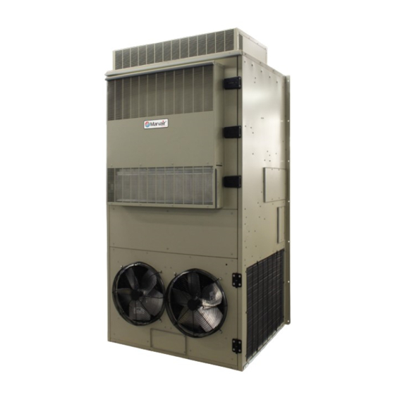
7.5, 10, 12.5 & 15 Ton 10EER Vertical
Wall Mount Air Conditioners
Installation & Operation Manual
10 EER Vertical Wall-Mount Air Conditioners
MODELS:
MGA3090A • MGA3120A
MGA3150A • MGA3180
(Dual Compressor)
IMPORTANT
This manual may include information for options and features which may not be
included on the unit being installed. Refer to the unit data label or Model Identification
to determine which features and options this unit is equipped with.
INSTALLER: Affix the instructions on the inside of the building adjacent to the thermostat.
END USER: Retain this manual for future reference.
Manufactured By:
Marvair, An ACS Brand
P.O. Box 400 • Cordele, Georgia 31010 • 156 Seedling Drive • Cordele, Georgia 31015
(229) 273-3636 • Fax (229) 273-5154
www.Marvair.com
The most current version of this manual can be found at www.Marvair.com.
Marvair MGA3090-3180 Wall Mount AC I&O Manual 03/2024 Rev.19
Advertisement
Table of Contents
Troubleshooting

Related Manuals for ACS Marvair MGA3090A


Summary of Contents for ACS Marvair MGA3090A
- Page 1 INSTALLER: Affix the instructions on the inside of the building adjacent to the thermostat. END USER: Retain this manual for future reference. Manufactured By: Marvair, An ACS Brand P.O. Box 400 • Cordele, Georgia 31010 • 156 Seedling Drive • Cordele, Georgia 31015 (229) 273-3636 • Fax (229) 273-5154 www.Marvair.com...
- Page 2 Failure to comply could result in minor personal injury and/or property damage. CAUTION Used to point out helpful info that will result in improved installation, reliability or operation. IMPORTANT SPECIFICATIONS SUBJECT TO CHANGE WITHOUT NOTICE. © 03/2024 Marvair, An ACS Brand Marvair MGA3090-3180 Wall Mount AC I&O Manual 03/2024 Rev.19...
-
Page 3: Table Of Contents
WARNING • If the information in these instructions are not followed exactly, a fire may result causing property damage, personal injury or loss of life. • Read all instructions carefully prior to beginning the installation. Do not begin installation if you do not understand any of the instructions. •... - Page 4 Chapter 4 Troubleshooting Overview ..............................27 Failure Symptoms Guide ........................28 Compressor Troubleshooting .........................29 Chapter 5 Maintenance Scheduled Maintenance .........................30 Chapter 6 Warranty Limited Product Warranty ........................31 Chapter 7 Start-Up Check List Start-Up Check List ..........................32 Illustrations Figure 1. PLC ............................10 Figure 2a. Typical Electrical Schematic - MGA3090A................13 Figure 2b.
-
Page 5: General Description
Chapter 1 Description & Specifications General Description The Marvair MGA3090A, MGA3120A, MGA3150A & MGA3180A are a series of vertical wall- mounted air conditioning systems that provide heating, cooling, and ventilation for telecommunication shelters, and other applications with high internal heat gains. The series is available in nominal cooling capacities of 90,000-180,000 BTUH. -
Page 6: Model Identification
Model Identification The model identification number is found on the data sticker. Rating plate located on side panel. Example Position Unit Designation/Family M = Marvair Wall Mount D = Dry Bulb Sensor Indoor Air Quality E = Dry Bulb Sensor w/Dirty Filter Energy Efficiency Ratio (EER) G = 10 Features G = Dirty Filter Sensor... -
Page 7: Table 1 Efficiency And Capacity Ratings At Ansi/Ahri Standard 390
Note: Follow local codes and standards when designing duct runs to deliver the required airflow. Minimize noise and excessive pressure drops caused by duct aspect ratio changes, bends, dampers and outlet grilles in duct runs. Model Number Cooling BTUH Rated Air Flow (CFM) MGA3090A 89,000 3,500... -
Page 8: Table 4 Dual Compressor Cooling Performance (Btuh) At Various Outdoor Temperatures
Outdoor Temperature Return Air Model Cooling DB/WB 75°F 80°F 85°F 90°F 95°F 100°F 105°F 110°F 115°F 120°F 125°F 130°F Number Capacity °F (°C) (24°C) (27°C) (30°C) (32°C) (35°C) (38°C) (41°C) (43°C) (46°C) (49°C) (52°C) (54°C) BTUH 72/61 Total 92,382 89,178 86,063 82,859 79,655 76,451 73,247 70,132 68,530 66,928 65,326 63,724 (22/16) Sensible 68,795 67,490 66,228 64,938 63,655 62,379 61,110 59,883 59,255 58,629 58,004 57,381... -
Page 9: Table 7 Shipping Weights & Dimensions
Shipping Dimensions Unit Weight Shipping Weight Model Height Width Depth Inches Inches Inches MGA3090A 1,085 1,160 2,489 1,422 1,219 MGA3090A Reverse Flow 1,085 1,160 2,489 1,422 1,219 MGA3090A Reverse Flow w/Economizer 1,131 1,210 2,489 1,422 1,219 MGA3120A 1,195 1,277 2,489 1,422 1,219 MGA3120A Reverse Flow... -
Page 10: General Operation
General Operation Optional Hot Gas By-Pass Normally used in specialty applications (i.e Magnetic Resonance Imaging (MRI) buildings) to prevent magnetic voltage disturbance caused by cycling. This technology is applied in this product to extend the operation envelope for the compressor to 20º F (-6.6ºC). Combined with a condenser low ambient Fan Cycle feature, compressor operation can be extended to 0º... -
Page 11: Optional Controls And Packages
a common alarm output. All other outputs are used for Air conditioning operation. Along the bottom of the PLC, there are 7 banks of terminals, which represents 4 analog outputs, 8 digital inputs and 8 Analog inputs. The PLC also comes with communication interface for MODBUS RS485, BACnet MSTP, BACnet IP and MODBUS IP. -
Page 12: 1.8 Electrical Operation
Dual Compressors With Lead/Lag Operation Freeze Sensor On Indoor Coil Prevents frost on the indoor coil caused by a loss of air flow or restrictive duct work. Filter Access From Return Air Grille Factory or field installed filter bracket allows changing and access to the filters from the return air grille. See model ID, special option code “I”. -
Page 13: Figure 2A. Typical Electrical Schematic - Mga3090A
480/240/208 TRANSFORMER 24 VAC Figure 2a. Typical Electrical Schematic - MGA3090A Marvair MGA3090-3180 Wall Mount AC I&O Manual 03/2024 Rev.19... -
Page 14: Figure 2B. Typical Electrical Schematic - Mga3120A & Mga3150A
480/240/208 TRANSFORMER 24 VAC Figure 2b. Typical Electrical Schematic - MGA3120A & MGA31050A Marvair MGA3090-3180 Wall Mount AC I&O Manual 03/2024 Rev.19... -
Page 15: Figure 2C. Typical Electrical Schematic - Mga3180A
480/240/208 TRANSFORMER 24 VAC Figure 2c. Typical Electrical Schematic - MGA3180A Marvair MGA3090-3180 Wall Mount AC I&O Manual 03/2024 Rev.19... -
Page 16: Chapter 2 Installation
Chapter 2 Installation WARNING Failure to observe and follow Warnings and Cautions and these Instructions could result in death, bodily injury or property damage. Read this manual and follow its instructions and adhere to all Cautions and Warnings in the manual and on the unit. Equipment Inspection Concealed Damage Inspect all cartons and packages upon receipt for damage in transit Remove cartons and check for... -
Page 17: Installation Materials
Keep duct lengths as short as possible. Do not obstruct airflow through the unit. Duct work should be designed and installed in accordance with all applicable safety codes and standards. Marvair strongly recommends referring to the current edition of the National Fire Pro- tection Association Standards 90A and 90B before designing and installing duct work. - Page 18 Accessories: The package may include other factory-supplied items (optional): Description S/07846 CommStat 4 HVAC Controller, Solid State Lead/Lag Controller K/400119-100 MPC-10 PLC Controller 50123 Digital thermostat. 1 stage heat, 1 stage cool. 7 day programmable. Fan switch: Auto & On. Auto-change over. Keypad lockout. Non-volatile program memory. Supply Grille Description 93189...
-
Page 19: Porting And Duct Work
Porting and Duct Work General Information Note: The following instructions are for general guidance only. Due to the wide variety of installation possibilities, specific instructions will not be given. When in doubt, follow standard and accepted installation practices, or contact Marvair for additional assistance. -
Page 20: Installing The Lifting Brackets
Figure 3 Top Flange and Lifting Bracket Installation (Typical) Installing the Optional Lifting Brackets Lifting brackets are available which can be installed on the top of the side panels. These brackets allow the unit to be picked up using lifting eyes in the brackets. Attach the brackets to the left and right side panels as shown in Figure 3. -
Page 21: Compressor Chocks Removal
Compressor Chocks Removal WARNING Wooden compressor chocks must be removed and discarded when unit is at final shipping destination. If chocks are not removed damage to compressor or copper system may occur. Final installer must remove wooden chocks from beneath compressors. Remove screw from in front of wooden chock, pull chock out from underneath compressor and discard both screw and wooden chock. -
Page 22: Unit Support Recommendations
Unit Support Recommendations Guidelines: 1. For units 15 tons and larger, the base of the unit should be fully supported in transit and in stationary applications to not allow deflection in static or dynamic loading. 2. For units ranging from 7.5 tons to 12.5 tons, the base of the unit should be fully supported in transit to not allow deflection in dynamic loading. - Page 23 The units may incorporate an internal crankcase heater for compressor protection. The crankcase heater must be energized for at least 24 hours prior to starting the compressor. Scroll compressors, like several other types of compressors, will only compress in one rotational direction. The direction of rotation is not an issue with single-phase compressors since they will always start and run in the proper direction.
-
Page 24: Figure 7A. Humidistat Wiring To A Marvair Air Conditioner With Reheat
CAUTION The external breaker(s) that provide power to the air conditioner must be sized per the maximum Fuse Size (MFS) shown on the Unit's data label. Low Voltage Wiring IMPORTANT. The following instructions are generic wiring instructions and may not be applicable for air conditioners with various options. -
Page 25: Figure 7B. Commstat 4 Connection Diagram
COMMSTAT4 HVAC UNIT 24V/ CN10 MODICON M172 SCHNEIDER TM172PDG28RI ELECTRIC O/Y2 CN18 CN19 RS 485-2 24 V RS 485-1 NOTES: 1) CommStat4 need to be set to mechanical cooling mode. That is, "Setting 19" needs to be set to "0". Economizer or Mechanical Cooling operation is decided by the unit. 2) These are field wiring. -
Page 26: Chapter 3 Start-Up
Chapter 3 Start-Up Check-Out of Cooling Cycle Important: Be sure that the crankcase heater (if used) has been energized for at least 24 hours before starting the unit(s). Double-check all electrical connections before applying power. All air conditioners with scroll compressors running on 3Ø power must be checked for proper rotation during the initial start-up. -
Page 27: Chapter 4 Troubleshooting
Chapter 4 Troubleshooting Overview The middle front panel provides access to the electrical/control box and to the filters. This panel has hinges on the left and right hand side. This panel should ONLY be opened by using the two hinges on the left side OR the two hinges on the right side. -
Page 28: Failure Symptoms Guide
Failure Symptoms Guide PROBLEM/SYMPTOM LIKELY CAUSE(S) CORRECTION A. Unit does not run. 1. Power supply problem. 1. Check power supply for adequate phase and voltage. Check wiring to unit and external breakers or fuses. NOTE: An internal anti-short-cycle 2. Tripped internal disconnect. 2. -
Page 29: Compressor Troubleshooting
Compressor Troubleshooting NOTE: It is important to rule out other component failures before condemning the compressor. The following electrical tests will aid diagnosis: 1. Start-Up Voltage: Measure the voltage at the compressor contactor during start-up. The voltage must exceed the minimum shown in Table 5, section 2.2, or compressor failure is likely. A low voltage condition must be corrected. -
Page 30: Chapter 5 Maintenance
Chapter 5 Maintenance The middle front panel provides access to the electrical/control box and to the filters. This panel has hinges on the left and right hand side. This panel should ONLY be opened by using the two hinges on the left side OR the two hinges on the right side. -
Page 31: Chapter 6 Warranty
Chapter 6 Warranty Marvair, Inc. Limited Product Warranty Marvair Inc., warrants its products to be free from defects in materials and workmanship under normal use to the original purchaser for the period of time in the table below. If any part of your product fails within 12 months from start-up, or 18 months from shipment from the factory, whichever comes first, Marvair, Inc. -
Page 32: Start-Up Check List
Chapter 7 Start-Up Check List The middle front panel provides access to the electrical/control box and to the filters. This panel has hinges on the left and right hand side. This panel should ONLY be opened by using the two hinges on the left side OR the two hinges on the right side. - Page 33 Condensate Section Has water been placed in drain pan to confirm proper drainage? ❒Yes ❒No Are correct filters in place? ❒Yes ❒No Refrigerant Piping If leaks are found, report any leaks to Marvair Warranty Service Dept. C. Check Rated Voltage at Terminal Block for Imbalance before starting of Unit. ❒208/230V 1 Phase ❒208/230V 3 Phase ❒460V 3 Phase...
- Page 34 D. Heating Mode Check & Record Readings Circuit 1 Circuit 2 (if applicable) Room Temperature ________ ________ Outside Temperature ________ ________ Evap. Entering Air DB Temp ________ ________ Evap. Entering Air WB Temp ________ ________ Evap. Leaving Air DB Temp ________ ________ Evap.
- Page 35 After 10 minutes of compressor operation, record the following: Circuit 1 Circuit 2 (if applicable) Room Temperature ________ ________ Outside Temperature ________ ________ Suction Pressure ________ ________ Suction Line Temperature ________ ________ Discharge Pressure ________ ________ Discharge Line Temperature ________ ________ Entering Condenser Air ________...
-
Page 36: Appendix A: Plc Setup And Operation
Appendix A: PLC SetUp and Operation These instructions are intended to assist users in navigating through the different PLC screens as well as understanding the variables located on each screen. Note: 1. Screen numbers are referenced from “Digital Inputs” which is the first screen seen when PLC’s display is populated. - Page 37 Figure 1 shows the digital input screen when all pressure switches are properly functioning, and the emergency shutdown is closed. Figure 1 Table 1 shows the designations for each input and their status based on the input. Digital Designation Normal Status Fault Status Input HPS_1 [HIGH PRESSURE - CIRCUIT 1]...
- Page 38 “COOL_OP” represents the setting on the PLC which allows the HVAC unit to operate with a different number of cooling stages. 1. 2 Fixed Compressor – This allows the unit to operate with 2 independent cooling stages. Therefore, allows the stages to be turned on as needed which effective provides a more optimal management of the temperature of the space being cooled.
- Page 39 Motor Operation This screen allows the end user to configure the operation of the air movers in the HVAC unit. 1. FAN STATUS – This setting manages the indoor motor operation. b. AUTO (Default) – This setting allows the indoor blower to run based on a request for an air conditioning operation.
- Page 40 Default Values: Cooling (%) Stage 1: 50 Stage 2: 55 (1st Stage Speed – 2 Fixed Compressor Setting. See “COOL_OP”) Stage 3: 60 Stage 4: 60 Stage 5: 65 (2nd Stage Speed– 2 Fixed Compressor Setting. See “COOL_OP”) Heating (%) Stage 1: 60 Fan Only (%) Stage 1: 60...
- Page 41 3. TEMP SETPOINT – Temperature Differential required between the space and the outside air at which economizing is allowed. (Default = 70.0ºF) 4. ENTHALPY SETPOINT – Enthalpy Differential required between the space and the outside air at which economizing is allowed. (Default = 50%) 5.
- Page 42 REFRIGERATION Allows the user to the monitor the liquid line temperature of each refrigeration circuit as well as offset the measured values. 1. H. PRESS – A|B represents the liquid line temperature of circuit 1 and 2 respectively. 2. S. PRESS – A|B represents the suction pressure of circuit 1 and 2 respectively. (Not monitored) Note: The system modulates to maintain a liquid line temperature of 100ºF.
- Page 43 6. Humidity a. HUMIDITY_SP – This variable represents the reference value used to trigger the dehumidification operation. (Default = 50%) b. EN – This variable allows the end user to Enable or Disable the dehumidification operation. Note that this is unit dependent and supporting utility should be capable of supporting the full load capacity of the HVAC unit.
-
Page 44: Figure 1. Plc
PLC GENERAL PURPOSE INPUT/OUTPUT Analogue Input Name Variable Type AIL1 Liquid Line Temp – Circuit 1 AIL2 Liquid Line Temp – Circuit 2 AIL3 Outdoor Air Temperature VOLTAGE [0-10VDC] AIL4 Outdoor Air Humidity VOLTAGE [0-10VDC] AIL5 Mixed Air Temperature AIL6 Emergency Shutdown Input BOOL [N.C] AIL7... -
Page 45: Appendix B: Plc Sequence Of Operation
Appendix B: PLC Sequence of Operation Equipment should go through a commissioning/start up sequence recommended by manufacturer to ensure safety and system reliability. This document is only valid if the system is used as intended. This document defines the manner and method of control of the system. It will cover the following operations and protections. - Page 46 1.0 - Cooling Operation 1.1 – Mechanical Cooling Only This section will describe the sequence of operation which takes place during Direct Expansion (DX) cooling with the OA dampers at their minimum position. In normal operating mode, a request for “Stage 1 Cooling (Y-input)” via communication (BACnet or MODBUS), Digital Input or Onboard Thermostat, energizes the Indoor Blower Motor and Compressor 1 relay outputs on the PLC continuously.
- Page 47 between 55ºF and 60ºF. The cooling stages remain energized until the Cooling Setpoint is satisfied. Note that in this mode, the economizer and the compressor CANNOT operate simultaneously. 2. Using Off-the-shelf Thermostat If economizer enable setpoint is satisfied, the Economizer Damper modulates to maintain the Room Temperature.
- Page 48 3.3 – Anti-Short Cycle This is a built-in protection mechanism that increases the reliability of the compressor by protecting it from excessive short cycling. When the compressor goes off, due to any fault, emergency or if the cooling setpoint is satisfied, a built-in 3-minute timer locks the compressor out.
-
Page 49: Appendix C: Plc Modbus Variable
Appendix C: PLC MODBUS Variables Address Name Data Type Default Min Max Access Level Description MEMORY LOCATION FOR MONITORING COM- 8965 Y_MEM Boolean READ PRESSOR 1 - STAGE 1 COOLING REQUEST (INPUT) MEMORY LOCATION FOR MONITORING COM- 8966 Y2_MEM Boolean READ PRESSOR 2 - STAGE 1 COOLING REQUEST (INPUT) - Page 50 Address Name Data Type Default Min Max Access Level Description MEMORY LOCATION FOR SETTING INDOOR MO- 9003 IBM_OffDelay Real READ/WRITE TOR TIME OFF DELAY MEMORY LOCATION FOR SETTING OUTDOOR HU- 9005 ECON_HumSP Real READ/WRITE MIDITY ENABLE (ONLY APPLICABLE IF LOCATION “9090”...
- Page 51 Address Name Data Type Default Min Max Access Level Description Signed MONITORS THE CURRENT SPEED OF INDOOR 9063 BlowerSpeed READ/WRITE 16-bit MOTOR. (VALUE SHOULD BE DIVIDED BY 10) Signed SET OPERATING SPEED OF THE INDOOR MOTOR 9064 OFMSpeed READ/WRITE 16-bit 0: OUTDOOR FAN RUNS AT “OFMSpeed”...
-
Page 52: Appendix D: Fresh Air Damper Installation
Appendix D: Fresh Air Damper Installation Marvair MGA3090-3180 Wall Mount AC I&O Manual 03/2024 Rev.19... - Page 53 Fresh Air Hood Adjustment (non-economozer air conditioners only) The fresh air hood is located on the inside, behind the slots on the bottom front panel. To access the hood, remove the screws that hold the front panel. The air flow can be adjusted from no (0%) fresh air to approximately 15% of rated air flow of fresh air, in 5% increments.
-
Page 54: Appendix E: Mga3150A/3180A Reverse Flow W/Economizer Exhaust Hood Installation
Appendix E: MGA3150A/3180A Reverse Flow w/Economizer Exhaust Hood Installation A. MAKE SURE FACTORY SUPPLIED GASKET IS PROPERLY ATTACHED TO THE BOTTOM FLANGES OF THE HOOD ASSY (ITEM 1) B. PLACE HOOD ASSY (ITEM 1) ON TOP OF UNIT WITH SLOTTED VENTS TOWARDS THE FRONT OF THE UNIT C.
Need help?
Do you have a question about the Marvair MGA3090A and is the answer not in the manual?
Questions and answers