Table of Contents
Advertisement
Quick Links
Installation & Operation Manual
11 EER Vertical Wall-Mount Air Conditioners
8AA1024A-8AA1060A (Single Stage)
8AA2036A-8AA2060A (2-Stage)
This manual may include information for options and features which may not be
included on the unit being installed. Refer to the unit data label or Model Identification
to determine which features and options this unit is equipped with.
INSTALLER: Affix the instructions on the inside of the building adjacent to the thermostat.
END USER: Retain this manual for future reference.
Marvair, An AirX Climate Solutions Brand
P.O. Box 400 • Cordele, Georgia 31010 • 156 Seedling Drive • Cordele, Georgia 31015
E-mail: marvairsales@airxcs.com • Internet: www.Marvair.com
The most current version of this manual can be found at www.Marvair.com.
MODELS:
IMPORTANT
Manufactured By:
(229) 273-3636 • Fax (229) 273-5154
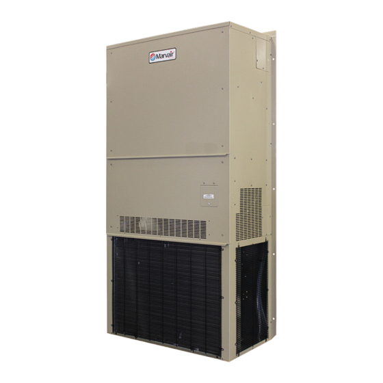
Air Conditioner Product Manual
Vertical Wall-Mount Air Conditioners
with Front Control Box Panel
Marvair 8AA1024A-1060A & 8AA2036A-2060A I&O Manual 05/2023 Rev.3
Advertisement
Table of Contents
Troubleshooting

Subscribe to Our Youtube Channel
Related Manuals for ACS Marvair 8AA1024A-8AA1060A


Summary of Contents for ACS Marvair 8AA1024A-8AA1060A
- Page 1 Air Conditioner Product Manual Vertical Wall-Mount Air Conditioners with Front Control Box Panel Installation & Operation Manual 11 EER Vertical Wall-Mount Air Conditioners MODELS: 8AA1024A-8AA1060A (Single Stage) 8AA2036A-8AA2060A (2-Stage) IMPORTANT This manual may include information for options and features which may not be included on the unit being installed.
- Page 2 How To Use This Manual This manual is intended to be a guide to the Marvair Wall Mount family of vertical air conditioners. It contains installation, troubleshooting, maintenance, warranty, and application information. The information contained in this manual is to be used by the installer as a guide only.
-
Page 3: Table Of Contents
WARNING • If the information in these instructions are not followed exactly, a fire may result causing property damage, personal injury or loss of life. • Read all instructions carefully prior to beginning the installation. Do not begin installation if you do not understand any of the instructions. •... - Page 4 Table of Contents Chapter 5 Troubleshooting Overview ..............................45 Failure Symptoms Guide ........................45 Compressor Troubleshooting .........................46 Control Board Diagnosis ........................47 Chapter 6 Maintenance Scheduled Maintenance .........................48 Chapter 7 Warranty Marvair Limited Product Warranty ......................49 Chapter 8 Start-Up Checklist Start-Up & Commissioning Form ......................50 Appendix A Installation Instructions for Field Installed Electric Heaters ................54 Illustrations...
-
Page 5: General Description
Chapter 1 Description & Specifications General Description The Marvair 8AA are a series of vertical wall-mounted air conditioning systems that provide heating, cooling, and ventilation for electronic equipment shelters, process control centers, and other applications with high internal heat gains. The series includes multiple sizes and nominal cooling capacities from 24,000 to 60,000 BTUH. -
Page 6: Table 3 Cfm @ External Static Pressure
MODEL 0.10 0.15 0.20 0.25 0.30 0.40 0.50 8AA1024A 8AA1030A 1200 1150 1100 1050 1000 8AA1036A 1290 1230 1170 1115 1060 1000 8AA1042A 1500 1430 1360 1295 1230 1160 1070 8AA1048A 1900 1850 1800 1700 1600 1500 1350 8AA1060A 1900 1850 1800 1700... -
Page 7: Model Identification
Model Identification Example Position 10 11 12 13 14 15 16 17 18 19 20 21 22 23 24 25 26 27 28 29 30 Unit Designation/Family 8 = Marvair Wall Mount D = Dry Bulb Sensor E = Dry Bulb Sensor w/Dirty Filter Energy Efficiency Ratio A = 11 17 Indoor Air Quality Features... -
Page 8: General Operation
General Operation Model Ventilation Configuration Temperature Range Non-Economizer Standard ("N"), Desert Duty ("ND") 0ºF – 131ºF (-18ºC – 55ºC) With Economizer Standard ("CE"), Desert Duty ("CD") -40ºF – 131ºF (-40ºC – 55ºC) Table 5. Ambient Temperature Operating Range Refrigerant Cycle (Cooling Mode) Marvair air conditioners use R-410A refrigerant in a conventional vapor-compression refrigeration cycle to transfer heat from air in an enclosed space to the outside. - Page 9 below 50°F (10°C), the fan cycle switch is in the circuit; when temperatures are 50° F (10°C) or higher, the fan cycle switch is not in the circuit. The fan cycle control is used with a TXV to prevent excessive cycling or "hunting"...
- Page 10 ler (CommStat Touch, CommStat 4, CommStat 3 HVAC Controller), most times the dehumidification option is only necessary on one of the two units. It is possible for one unit to be operating in the cooling mode while the unit with dehumidification is operating at the same time. If the cooling unit does not maintain the shelter temperature set point, the unit with dehumidification will go into the cooling mode.
-
Page 11: Electrical Operation
Electrical Operation The compressor and condenser fan are energized with a contactor controlled by a 24 VAC pilot signal. Some compressors incorporate an internal PTC crankcase heater that functions as long as primary power is available. The heater drives liquid refrigerant from the crankcase and prevents loss of lubrication caused by oil dilution. -
Page 12: Figure 1A. Typical Electrical Schematic - Non-Economizer
TEST IBMSEL OFMSEL 0-10V 0-10V IBMSEL OFMSEL Figure 1a. Typical Electrical Schematic (Non-Economizer) Marvair 8AA1024A-1060A & 8AA2036A-2060A I&O Manual 05/2023 Rev.3... -
Page 13: Figure 1B. Typical Electrical Schematic - W/Economizer
TEST IBMSEL OFMSEL 0-10V 0-10V IBMSEL OFMSEL Figure 1b. Typical Electrical Schematic - w/Economizer Marvair 8AA1024A-1060A & 8AA2036A-2060A I&O Manual 05/2023 Rev.3... -
Page 14: Figure 1C. Typical Electrical Schematic - W/Economizer (Alternate Construction)
Figure 1c. Typical Electrical Schematic - w/Economizer (Alternate Construction) Marvair 8AA1024A-1060A & 8AA2036A-2060A I&O Manual 05/2023 Rev.3... -
Page 15: Figure 1D. Typical Electrical Schematic - W/Economizer (Alternate Construction)
Figure 1d. Typical Electrical Schematic - w/Economizer (Alternate Construction) Marvair 8AA1024A-1060A & 8AA2036A-2060A I&O Manual 05/2023 Rev.3... -
Page 16: Figure 1E. Typical Electrical Schematic - W/Economizer (Alternate Construction)
Figure 1e. Typical Electrical Schematic - w/Economizer (Alternate Construction) Marvair 8AA1024A-1060A & 8AA2036A-2060A I&O Manual 05/2023 Rev.3... -
Page 17: Economizer Components
Chapter 2 Electronic Control Board Introduction WARNING Failure to observe the instructions contained in this document may result in personal injury and/or property damage and may void the warranty. Read this manual before installing, replacing or using this product. Marvair’s proprietary Printed Circuit Board (PCB) sets the standard for the industry in flexibility, reliability and performance. -
Page 18: Installation And Replacement
Item Description Economizer Actuator Output 2-10 VDC Outdoor Motor Control Output 0-10 VDC or PWM Indoor Motor Control Output 0-10 VDC or PWM Enthalpy Sensor Signal Input 4-20mA Outdoor Sensor Signal 10K NTC (Heat Pumps) / Dry Bulb Sensor Signal Input 10K NTC (Systems Equipped with Dry Bulb Economizer) Supply Air Sensor Signal Input 10K NTC (Systems Equipped with Economizer) Defrost Sensor Signal Input 10k NTC (Heat Pumps Only) - Page 19 2.3.1 – Programming Menu Configuration 1. To Enter Programming Mode: • Press and hold the Menu button for 5 seconds until P-01 is displayed. 2. While in Programming Mode main menu: • Press the Menu button to enter the displayed parameter menu. •...
- Page 20 Configuration Menu Details 1. AC/HP Select: This setting allows the PCB to be configured for AC (air-conditioner) or HP (heat- pump). The system type is configured at the factory during production testing for the appropriate system type. The default system type is AC. 2.
- Page 21 for W2 (auxiliary / emergency heat). When the SCKT Set is set to Y (yes) the electric heat will not be allowed to operate with the compressor in the heat-pump mode. When set to Y (yes) and upon a request for W2 (auxiliary / emergency heat) the compressor will shut off and the electric heat will operate.
-
Page 22: Operation
the Dehum speed is 80% of maximum speed. The speed may be adjusted from 60-100% in 1% increments to meet desired airflow requirements. 18. DS Calibration: This setting is used to calibrate the defrost sensor from 0 to -18F. 19. SAS Calibration: This setting is used to calibrate the supply air sensor from 0 to -18F. 20. - Page 23 1.0 Indoor Blower Operation 1.1 G - Indoor Blower Only 1.2 Y1 - Indoor Blower Operation 1.3 Y2 - Indoor Blower Operation 1.4 W2 – Indoor Blower Operation 1.5 HUM – Indoor Blower Operation 2.0 Cooling Operation AC / HP 2.1 Mechanical Cooling (AC systems) 2.1.1 Partial Capacity 2.1.2 Full Capacity...
- Page 24 1.0 Indoor Blower Operation The speed at which the indoor blower will operate is based on the discrete operational inputs that have 24vac applied. These inputs are listed below. 1.1 G Input – A request for Fan Only (independent G-signal via Digital input or Modbus), results in the indoor motor turning “ON”...
- Page 25 2.1 Mechanical Cooling (AC systems) – This section will describe the sequence of operation which takes place during Direct Expansion (DX) cooling from a control standpoint. Note: The system type must be configured for “AC” operation in setting 1 of the configuration menu of the control board for proper AC system operation.
- Page 26 to the “Y1” speed setting on the board or via Modbus. It also outputs a request dependent (based on FCC IN) control signal for the Outdoor Fan Motor (Only applicable to ECM motors). In Stage 1 Cooling operation, the compressor operates at partial capacity and the indoor fan remains on continuously but the outdoor fan modulates based on liquid line temperature.
-
Page 27: Figure 2. Enthalpy Sensor Temperature Control Points
Enthalpy Setpoint is Setting 14 in control board configuration menu. Options A= 73ºF B= 70ºF C= 67ºF D= 63ºF E= 55ºF All settings are @ 50%Rh Figure 2. Enthalpy Sensor & Temperature Control Points Enthalpy Operation On a call for cooling from the wall-mounted thermostat, if outdoor conditions are suitable, the sensor will open the damper and admit outside air (i.e., economizer free cooling). -
Page 28: Figure 3. Dry Bulb Sensor
Figure 3. Dry Bulb Sensor On a call for cooling from the wall-mounted thermostat, if outdoor conditions are suitable, the sensor will open the damper and admit outside air (i.e., economizer free cooling). If the outdoor ambient is too hot (dry bulb sensor only), the sensor will place the actuator in the closed or minimum open position and activate mechanical cooling. - Page 29 on the fan purge timer setpoint (default 90 seconds) selected in setting 3 of the configuration menu of the control board. Note: A request for Cooling and Heating at the same time is not allowed and control board will not allow the electric heat to operate. 4.2 Heat Pump Heating Operation –...
- Page 30 the heating setpoint is satisfied, the Indoor motor continues to run based on the fan purge timer setpoint (default 90 seconds) selected in setting 3 of the configuration menu of the control board. When the system is operating in Heap Pump mode the electric heat is considered as supplemental heat and will only be allowed under certain conditions due to additional features that may be used.
- Page 31 set on the control board for setting 7 in the configuration menu. The outdoor fan will speed up and slow down between liquid line temperature of 80F and 115F. Systems with (PSC Outdoor Motors) utilizes a Fan Cycle Switch which closes at 400 PSIG to energize the OFR (outdoor fan relay) to start the outdoor fan which runs until the switch reopens (at 290 PSIG).
- Page 32 The sensor is secured to the common suction line of the system to monitor the suction line temperature. This condition describes the abnormal fall in Suction Line Temperature below 9ºF. This fault will only be active when the Low-Pressure Sensor detects suction line temperatures below 9ºF during a request for Cooling / Heat pump heating.
- Page 33 Note: The compressor and electric heat WILL NOT operate while in the emergency ventilation mode. 7.3 Forced Cooling (economizer equipped systems) – During economizer cooling, if a request for “Forced Cooling” (FC-signal via Digital input or Modbus) is present. The control board will force the economizer to close and start the compressor to operate at full capacity cooling.
-
Page 34: Chapter 3 Installation
Chapter 3 Installation WARNING Failure to observe and follow Warnings and Cautions and these Instructions could result in death, bodily injury or property damage. Read this manual and follow its instructions and adhere to all Cautions and Warnings in the manual and on the unit. -
Page 35: Table 6 Minimum Clearances
the heater element. This includes proper supply duct sizing, sufficient quantity of supply registers, and adequate return and filter areas. Duct work must be of correct material and must be properly insulated. Duct work must be constructed of galvanized steel with a minimum thickness of .019 inches. -
Page 36: Installation Materials
Installation Materials Installation Kits Marvair air conditioners are shipped with one 12 Ga. "L" shaped bottom bracket. If you have not yet unpacked the unit, follow the instructions in section 2.1. All units have built-in full length mounting flanges. Therefore, use of mounting brackets is not required. Kit Components: 1. -
Page 37: Porting And Duct Work
Additional Items Needed: Additional hardware and miscellaneous supplies (not furnished by Marvair ) are needed for installation. ® For example, the list below contains approximate quantities of items typically needed for mounting a unit on a wood frame wall structure. Concrete or fiberglass structures have different requirements. (10) 3/8"... -
Page 38: Fresh Air Hood Installation
When installing the wall sleeve, the supply opening must be on top. The supply opening is smaller than the return air opening. Ducting Extensions should be cut flush with the inside wall for applications without duct work. Applications using duct work should be designed and installed in accordance with all applicable safety codes and standards. -
Page 39: Bracket Installation
Bracket Installation 1. All models have built-in mounting flanges. 2. Apply a bead of silicone sealer on the wall side of the bottom support brackets on the unit. Circle the mounting holes with the silicone bead. 3. Refer to Figure 4. Attach the bottom support bracket to the wall using appropriate 3/8" diameter hardware. -
Page 40: Electrical Connections
Electrical Connections WARNING ELECTRICAL SHOCK HAZARD Failure to follow safety warnings exactly could result in serious injury, death, and/or property damage. Turn off electrical power at fuse box or service panel BEFORE making any electrical connections and ensure a proper ground connection is made before connecting line voltage. - Page 41 2. Connect the wires to the input side of the internal breaker or terminal block (L1 & L2 for single- phase units; L1, L2, & L3 for three-phase models). 3. Install the ground wire on the ground lug. 4. For units designed for operation on 208/230V, 60Hz power supply, the transformer is factory wired for a 230V power supply.
-
Page 42: Figure 6A. Humidistat Wiring To A Marvair Air Conditioner With Reheat
CommStat 4 Lead /Lag Controller Please refer to the Product Data sheet for the Commstat 4 controller for complete instructions on installing and programming this controller. Figure 6a. Humidistat Wiring to a Marvair Air Conditioner with Reheat. Figure 6b. Thermostat Connection Diagram Marvair 8AA1024A-1060A &... -
Page 43: Figure 6C. Commstat™ 4 Hvac Controller Wiring Detail
, t l " l " 2 n i l n i l n i l " l " 2 " l " R l i t . t l A " " 1 A " " 2 n i l n i l n i l Figure 6c. -
Page 44: Chapter 4 Start-Up
Chapter 4 Start-Up Check-Out of Cooling Cycle Important: Be sure that the crankcase heater (if used) has been energized for at least 24 hours before starting the unit(s). Double-check all electrical connections before applying power. Marvair air conditioners with scroll compressors running on 3Ø power must be checked for proper rotation during the initial start-up. -
Page 45: Chapter 5 Troubleshooting
Chapter 5 Troubleshooting Overview A comprehensive understanding of the operation of the air conditioner is a prerequisite to troubleshooting. Please read the Chapter 1 for basic information about the unit. Marvair air conditioners are thoroughly tested before they are shipped from the factory. Although unlikely, it is possible that a defect may escape undetected, or damage may have occurred during transportation. -
Page 46: Compressor Troubleshooting
PROBLEM/SYMPTOM LIKELY CAUSE(S) CORRECTION C. Unit cycles on high/low pressure 1. Loss or restriction of airflow. 1. Check blower assembly for proper operation. Look limit. for airflow restrictions, e.g.. the air filter. Check blower motor and condenser fan. 2. Restriction in refrigerant circuit. 2. -
Page 47: Control Board Diagnosis
3. Motor Winding Resistances: Using a digital volt-ohm meter (VOM), measure the resistance across the compressor windings as shown below. SINGLE THREE PHASE PHASE > R > R Resistance can be measured as shown above. Any deviation from above values could indicate a defective compressor. -
Page 48: Chapter 6 Maintenance
Chapter 6 Maintenance Scheduled Maintenance Marvair strongly recommends that the air conditioner be serviced a minimum of twice a year – once prior to the heating season and once prior to the cooling season. At this time the filters, evaporator coil, condenser coil, the cabinet, and condensate drains should be serviced as described below. -
Page 49: Marvair Limited Product Warranty
Marvair, Inc. Limited Product Warranty Marvair Inc., warrants its products to be free from defects in materials and workmanship under normal use to the original purchaser for the period of time in the table below. If any part of your product fails within 12 months from start-up, or 18 months from shipment from the factory, whichever comes first, Marvair, Inc. -
Page 50: Start-Up & Commissioning Form
Start-Up & Commissioning Form Please complete the information on this form and return to Marvair by mail or fax. The mailing address and fax number can be found at the end of the form. A. Equipment Information Date: ________________Equipment Owner _______________________________________ Installing Company: _____________________________Installer: ____________________ Address: _______________________________________State _______________________ City: __________________________________________... - Page 51 ❒380V 3 Phase 50Hz. ❒575 3 Phase 60 Hz. Measured Line to Line Volts L1&L2_______V. L1&L3 ________V. L2&L3______V. (L1&L2 + L1&L3 + L2&L3)/3 = Avg. Voltage = _______________ Max. Deviation from avg. voltage = ______________volts Voltage imbalance = (100 x Max. Deviation)/avg. Voltage = ___________% A voltage deviation greater than 2% with the unit running should be addressed and corrected.
- Page 52 Circuit 1 Circuit 2 (if applicable) Room Temperature ________ ________ Outside Temperature ________ ________ Evap. Entering Air DB Temp ________ ________ Evap. Entering Air WB Temp ________ ________ Evap. Leaving Air DB Temp ________ ________ Evap. Leaving Air WB Temp ________ ________ Heater Contactor Amps (L1)
- Page 53 Circuit 1 Circuit 2 (if applicable) Room Temperature ________ ________ Outside Temperature ________ ________ Suction Pressure ________ ________ Suction Line Temperature ________ ________ Discharge Pressure ________ ________ Discharge Line Temperature ________ ________ Entering Condenser Air ________ ________ Leaving Condenser Air ________ ________ Evap.
-
Page 54: Installation Instructions For Field Installed Electric Heaters
WARNING FIRE HAZARD Improper adjustment, alteration, service, maintenance or installation could cause serious injury, death and/or property damage. Installation or repairs made by unqualified persons could result in hazards to you and others. Installation MUST conform with local codes or, in the absence of local codes, with codes of all governmental authorities have jurisdiction. - Page 55 Failure to follow safety warnings exactly could result in serious injury, death, and/or property damage. Turn off electrical power at fuse box or service panel BEFORE making any electrical connections and ensure a proper ground connection is made before connecting line voltage.
- Page 56 Marvair 8AA1024A-1060A & 8AA2036A-2060A I&O Manual 05/2023 Rev.3...
Need help?
Do you have a question about the Marvair 8AA1024A-8AA1060A and is the answer not in the manual?
Questions and answers