Table of Contents
Advertisement
Quick Links
Installation & Operation Manual
11 EER Vertical Wall-Mount
Air Conditioners w/Gas Heat
GAA1024A-GAA1030A-GAA1036A
GAA1042A-GAA1048A-GAA1060A
This manual may include information for options and features which may not be
included on the unit being installed. Refer to the unit data label or Model Identification
to determine which features and options this unit is equipped with.
INSTALLER: Affix the instructions on the inside of the building adjacent to the thermostat.
END USER: Retain this manual for future reference.
P.O. Box 400 • Cordele, Georgia 31010 • 156 Seedling Drive • Cordele, Georgia 31015
E-mail: marvairsales@airxcs.com • Internet: www.Marvair.com
The most current version of this manual can be found at www.Marvair.com.
MODELS:
IMPORTANT
Manufactured By:
Marvair, An AirX Climate Solutions Brand
(229) 273-3636 • Fax (229) 273-5154
Air Conditioner Product Manual
Vertical Wall-Mount Air Conditioners
with Gas Heat & Front Control Box Panel
Marvair GAA A/C w/Gas Heat I&O Manual 06/2023 Rev.5
Advertisement
Table of Contents

Related Manuals for ACS Marvair GAA1024A


Summary of Contents for ACS Marvair GAA1024A
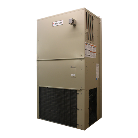
- Page 1 Air Conditioner Product Manual Vertical Wall-Mount Air Conditioners with Gas Heat & Front Control Box Panel Installation & Operation Manual 11 EER Vertical Wall-Mount Air Conditioners w/Gas Heat MODELS: GAA1024A-GAA1030A-GAA1036A GAA1042A-GAA1048A-GAA1060A IMPORTANT This manual may include information for options and features which may not be included on the unit being installed.
- Page 2 How To Use This Manual This manual is intended to be a guide to Marvair GAA family of vertical air conditioners with gas heat. It contains installation, troubleshooting, maintenance, warranty, and application information. The information contained in this manual is to be used by the installer as a guide only. This manual does not supersede or circumvent any applicable national or local codes.
-
Page 3: Table Of Contents
WARNING - SAFETY REQUIREMENTS • If the information in these instructions are not followed exactly, a fire, carbon monoxide poisoning or explosion may result causing property damage, personal injury or loss of life. • Read all instructions carefully prior to beginning the installation. Do not begin installation if you do not understand any of the instructions. - Page 4 Chapter 5 – Checks and Adjustments Gas Supply Pressure ..........................48 Manifold Gas Pressure Adjustment ....................48 Natural Gas Input Rating Check ......................50 Orifice Sizing .............................50 LP Gas Conversion ..........................51 High Altitude Installations .........................53 Changing Orifices ..........................54 Main Burner Flame Check .........................55 Temperature Rise Range ........................55 Chapter 6 –...
-
Page 5: Chapter 1 - Description & Specifications 1.1 General Description
Tables Table 1. Minimum Clearances from Unprotected Combustible Material and For Service .....30 Table 2. Electrical Rating Designations ....................32 Table 3. Minimum Clearances from Unprotected Combustible Material and For Service .....36 Table 4. Gas Pressures ..........................40 Table 5. Natural Gas Input Rating ......................50 Table 6. -
Page 6: Model Identification
1.2 Model Identification Example Position Unit Designation/Family G = Marvair Wall Mount w/Gas Heat D = Dry Bulb Sensor Indoor Air Quality E = Dry Bulb Sensor w/Dirty Filter Energy Efficiency Ratio (EER) A = 11 G = Dirty Filter Sensor Features Refrigerant Type A = R-410a... -
Page 7: Sequence Of Operation - Heating Mode
1.5 Sequence of Operation - Heating Mode On a call for heat, two stage thermostat contact( s ) close, providing 24 VAC to “4” terminal on the ignition control. Draft inducer is energized at high speed ( B -W leads ) at line voltage. Air Pressure Switch ( ... -
Page 8: Ventilation Options
The gas heat and air conditioner has a LED indicator that shows operating status and simplifies service by flashing fault codes. On-Steady Control Operation Normal 1 Flash Open Air pressure switch, limit switch or flame rollout switch 2 Flashes Pressure switch stuck closed 3 Flashes Ignition ... -
Page 9: Economizer Operation - Cooling Cycle (Unit With Economizer Only)
Configuration “E”: Two-Position Motorized Fresh Air Damper w/Pressure Relief Ventilation & Independent Control Control Board/Factory Installed Relay Logic: The 92589 control board allows the position of the “E” damper to be set for desired outside air intake from fully closed to fully open. Setting 15 of the control board configuration menu allows the user to set the position from 20 (2VDC / Closed) to 100 (10VDC 100% open). -
Page 10: Chapter 2 Electronic Control Board
Chapter 2 Electronic Control Board Introduction WARNING Failure to observe the instructions contained in this document may result in personal injury and/or property damage and may void the warranty. Read this manual before installing, replacing or using this product. Marvair’s proprietary Printed Circuit Board (PCB) sets the standard for the industry in flexibility, reliability and performance. -
Page 11: Installation And Replacement
Item Description Economizer Actuator Output 2-10 VDC Outdoor Motor Control Output 0-10 VDC or PWM Indoor Motor Control Output 0-10 VDC or PWM Enthalpy Sensor Signal Input 4-20mA Outdoor Sensor Signal 10K NTC (Heat Pumps) / Dry Bulb Sensor Signal Input 10K NTC (Systems Equipped with Dry Bulb Economizer) Supply Air Sensor Signal Input 10K NTC (Systems Equipped with Economizer) Defrost Sensor Signal Input 10k NTC (Heat Pumps Only) - Page 12 2.3.1 – Programming Menu Configuration 1. To Enter Programming Mode: • Press and hold the Menu button for 5 seconds until P-01 is displayed. 2. While in Programming Mode main menu: • Press the Menu button to enter the displayed parameter menu. •...
- Page 13 Configuration Menu Details 1. AC/HP Select: This setting allows the PCB to be configured for AC (air-conditioner) or HP (heat- pump). The system type is configured at the factory during production testing for the appropriate system type. The default system type is AC. 2.
- Page 14 for W2 (auxiliary / emergency heat). When the SCKT Set is set to Y (yes) the electric heat will not be allowed to operate with the compressor in the heat-pump mode. When set to Y (yes) and upon a request for W2 (auxiliary / emergency heat) the compressor will shut off and the electric heat will operate.
-
Page 15: Operation
the Dehum speed is 80% of maximum speed. The speed may be adjusted from 60-100% in 1% increments to meet desired airflow requirements. 18. DS Calibration: This setting is used to calibrate the defrost sensor from 0 to -18F. 19. SAS Calibration: This setting is used to calibrate the supply air sensor from 0 to -18F. 20. - Page 16 Indoor Blower Operation 1.1 G - Indoor Blower Only 1.2 Y1 - Indoor Blower Operation 1.3 Y2 - Indoor Blower Operation 1.4 W2 – Indoor Blower Operation 1.5 HUM – Indoor Blower Operation Cooling Operation AC / HP 2.1 Mechanical Cooling (AC systems) 2.1.1 Partial Capacity 2.1.2 Full Capacity 2.2 Mechanical Cooling (HP systems)
- Page 17 1.0 Indoor Blower Operation The speed at which the indoor blower will operate is based on the discrete operational inputs that have 24vac applied. These inputs are listed below. 1.1 G Input – A request for Fan Only (independent G-signal via Digital input or Modbus), results in the indoor motor turning “ON”...
- Page 18 2.1 Mechanical Cooling (AC systems) – This section will describe the sequence of operation which takes place during Direct Expansion (DX) cooling from a control standpoint. Note: The system type must be configured for “AC” operation in setting 1 of the configuration menu of the control board for proper AC system operation.
- Page 19 to the “Y1” speed setting on the board or via Modbus. It also outputs a request dependent (based on FCC IN) control signal for the Outdoor Fan Motor (Only applicable to ECM motors). In Stage 1 Cooling operation, the compressor operates at partial capacity and the indoor fan remains on continuously but the outdoor fan modulates based on liquid line temperature.
-
Page 20: Figure 1. Enthalpy Sensor & Temperature Control Points
Enthalpy Setpoint is Setting 14 in control board configuration menu. Options A= 73ºF B= 70ºF C= 67ºF D= 63ºF E= 55ºF All settings are @ 50%Rh Figure 1. Enthalpy Sensor & Temperature Control Points Enthalpy Operation On a call for cooling from the wall-mounted thermostat, if outdoor conditions are suitable, the sensor will open the damper and admit outside air (i.e., economizer free cooling). -
Page 21: Figure 2. Dry Bulb Sensor
Figure 2. Dry Bulb Sensor On a call for cooling from the wall-mounted thermostat, if outdoor conditions are suitable, the sensor will open the damper and admit outside air (i.e., economizer free cooling). If the outdoor ambient is too hot (dry bulb sensor only), the sensor will place the actuator in the closed or minimum open position and activate mechanical cooling. - Page 22 on the fan purge timer setpoint (default 90 seconds) selected in setting 3 of the configuration menu of the control board. Note: A request for Cooling and Heating at the same time is not allowed and control board will not allow the electric heat to operate. 4.2 Heat Pump Heating Operation –...
- Page 23 the heating setpoint is satisfied, the Indoor motor continues to run based on the fan purge timer setpoint (default 90 seconds) selected in setting 3 of the configuration menu of the control board. When the system is operating in Heap Pump mode the electric heat is considered as supplemental heat and will only be allowed under certain conditions due to additional features that may be used.
- Page 24 set on the control board for setting 7 in the configuration menu. The outdoor fan will speed up and slow down between liquid line temperature of 80F and 115F. Systems with (PSC Outdoor Motors) utilizes a Fan Cycle Switch which closes at 400 PSIG to energize the OFR (outdoor fan relay) to start the outdoor fan which runs until the switch reopens (at 290 PSIG).
- Page 25 The sensor is secured to the common suction line of the system to monitor the suction line temperature. This condition describes the abnormal fall in Suction Line Temperature below 9ºF. This fault will only be active when the Low-Pressure Sensor detects suction line temperatures below 9ºF during a request for Cooling / Heat pump heating.
- Page 26 10vdc signal from the ECO output of the control board to drive the motorized damper fully open. Note: The compressor and electric heat WILL NOT operate while in the emergency ventilation mode. 7.3 Forced Cooling (economizer equipped systems) – During economizer cooling, if a request for “Forced Cooling”...
-
Page 27: Chapter 3 Safe Installation Requirements
Chapter 3 Safe Installation Requirements WARNING - SAFETY REQUIREMENTS Improper adjustment, alteration, service, maintenance or installation could cause serious injury, death and / o r property damage. Installation or repairs made by unqualified persons could result in hazards to you and others. Installation MUST conform with local codes or, in the absence of local codes, with codes of all governmental authorities have jurisdiction. -
Page 28: Safety Rules
• Marvair GAA air conditioners with gas heat is only to be installed on the exterior of a building. • Never test for gas leaks with an open flame. Use a commercially available soap solution made spe- cifically for the detection of leaks to check all connections, as specified in Gas Supply and Piping, Final Check check of these instructions. - Page 29 WARNING: FROZEN AND BURST WATER PIPE HAZARD Failure to protect against the risk of freezing could result in property damage and / o r personal injury. Do not leave the structure unattended for long periods during freezing weather without turning off water supply and draining water pipes or otherwise protecting against the risk of frozen pipes and resultant damage.
-
Page 30: Chapter 4 Installation
Chapter 4 Installation WARNING CARBON MONOXIDE POISONING HAZARD Failure to properly vent this furnace or other appliances could result in death, personal injury and / o r property damage. If this furnace is replacing a previously common-vented furnace, it may be necessary to resize the existing vent system to prevent oversizing problems for the other remaining appliance( ... -
Page 31: Installation Requirements
La non-observation des AVERTISSEMENTS de sécurité peut causer des blessures graves ou mortelles ou des dégâts matériels. NE faites PAS fonctionner la chaudière dans une atmosphère corrosive contenant chlore, fluor ou tout produit chimique détériorant qui pourrait attaquer la chaudière et le système de ventilation, et permettre le déversement de produits de combustion dans un lieu habité. -
Page 32: Table 2. Electrical Rating Designations
the coil in the front of the unit. Both the intake and exhaust air must not be impeded or restricted by shrubbery or any other obstructions. 14. The power supply must have the appropriate voltage, phase and ampacity for the model selected. Refer to the data plate on the unit for ampacity requirements. -
Page 33: Dimensional Data
4.3 Dimensional Data Filter Size (inches) Shipping Weight BASIC MODEL GAA1024A GAA1030A GAA1036A BASIC MODEL GAA1024A GAA1030A GAA1036A FILTER SIZE - IN 30 x 16 x 2 SHIP WEIGHT - LBS FILTER SIZE - MM 762 x 406 x 51 SHIP WEIGHT - KG FILTER PART # 80138... -
Page 34: Figure 3B. Models Gaa1042A/Gaa1048A Dimensional Data
10 mm 117 mm 57 mm 502 mm 38 mm 502 mm 1054 mm COMPRESSOR ACCESS FROM LEFT SIDE Filter Size (inches) Shipping Weight BASIC MODEL GAA1042A GAA1048A FILTER SIZE - IN 18 x 24 x 1 BASIC MODEL GAA1042A GAA1048A FILTER SIZE - MM 457 x 610 x 25 SHIP WEIGHT - LBS... -
Page 35: Figure 3C. Models Gaa1060A Dimensional Data
92” [ 2337] 10 mm 117 mm 57 mm 38 mm 502 mm 502 mm 1054 mm COMPRESSOR ACCESS FROM LEFT SIDE Filter Size (inches) Shipping Weight BASIC MODEL GAA1042A GAA1048A GAA1060A FILTER SIZE - IN 18 x 24 x 1 BASIC MODEL GAA1042A GAA1048A GAA1060A FILTER SIZE - MM... -
Page 36: Equipment Inspection
4.4 Equipment Inspection Concealed Damage Inspect all cartons and packages upon receipt for damage in transit. Remove cartons and check for concealed damage. Important: Keep the unit upright at all times. Remove access panels and examine component parts. ( N ote: The top ( o ptional ) and bottom brackets are stored in the condenser air compart- ment. -
Page 37: Installation Materials
4.6 Installation Materials Installation Kits Marvair GAA air conditioners with gas heat have built-in mounting flanges that function as side brackets. All models require and are shipped with a bottom mounting bracket. There is also an air intake hood packed inside each unit and a vent hood. Standard Kit Components 1. -
Page 38: Porting And Duct Work
(10 ) 3 / 8 ” hex nuts 3 / 8 ” x 2-1 / 2 ” lag screws for bottom bracket (6 ) • Silicone Sealer to seal around cracks and openings • 7-conductor low voltage multi-colored wire cable ( i .e. thermostat wire) •... -
Page 39: Ducting
4.11 Ducting Extensions should be cut flush with the inside wall for applications without duct work. Applications using duct work should be designed and installed in accordance with all applicable safety codes and standards. Marvair strongly recommends referring to the current edition of the National Fire Protection Association Standards 90 A and 90 B before designing and installing ductwork. -
Page 40: Gas Supply And Piping
holes with the silicone bead. 6. Using an appropriate and safe lifting device, set the unit on the bottom support bracket mounted on the wall. You must stabilize the unit on the bracket with the lifting device or by some other means - the bracket alone is not sufficient. - Page 41 NOTE: In the state of Massachusetts. a. Gas supply connections MUST be performed by a licensed plumber or gas fitter. b. When flexible connectors are used, the maximum length shall not exceed 36” ( 9 15 mm ) . c. When lever handle type manual equipment shutoff valves are used, they shall be T-handle valves.
- Page 42 WARNING FIRE OR EXPLOSION HAZARD Failure to properly install metal gas connector could result in death, bodily injury and / o r property damage. A flexible corrugated metal gas connector must be properly installed, shall not extend through the side of the furnace, and shall not be used inside the furnace.
-
Page 43: Electrical Connections
Final Check of Gas Piping • Test all pipes for leaks. • If orifices were changed, make sure they are checked for leaks. • During pressure testing of gas supply piping system: a. If test pressure does not exceed 1 / 2 ” psi, isolate the furnace from the gas supply piping system by closing the equipment shutoff valve. - Page 44 CAUTION This system contains components that require phasing for correct rotation. Failure to observe rotation and correct on start-up will cause damage not covered by the warranty. ATTENTION Ce système contient des composants qui nécessitent un phasage pour une rotation correcte. Il faut observer le sens de rotation et le corriger tout de suite s’il y a lieu au démarrage, sous peine de dommages qui ne seraient pas couverts par la garantie.
-
Page 45: Figure 5A. Typical Electrical Schematic - 1Ø Power Supply
Figure 5a. Typical Electrical Schematic - 1Ø Power Supply Marvair GAA A/C w/Gas Heat I&O Manual 06/2023 Rev.5... -
Page 46: Figure 5B. Typical Electrical Schematic - 3Ø Power Supply
Figure 5b. Typical Electrical Schematic - 3Ø Power Supply Marvair GAA A/C w/Gas Heat I&O Manual 06/2023 Rev.5... -
Page 47: Venting Of The Furnace
4.17 Venting of the Furnace The wall mounted air conditioner with gas heat furnace is a Category I furnace, i.e., a central furnace which operates with a non-positive vent static pressure and with a flue loss not less than 17%. The furnace is fan assisted, i.e., an appliance equipped with an integral means to either draw or force products of combustion through the combustion changer and ... -
Page 48: Chapter 5 Checks And Adjustments
Chapter 5 Checks and Adjustments The unit must be operating in the heating mode while doing the following check and adjustments. Refer to the Start up instructions for starting the unit. WARNING ELECTRICAL SHOCK, FIRE, EXPLOSION OR CARBON MONOXIDE POISONING HAZARD Failure to follow safety warnings exactly could result in serious injury, death and ... -
Page 49: Figure 7. Gas Valve Manifold Pressure Tap
Figure 7. Gas Valve Manifold Pressure Tap 2. Turn gas ON. Operate furnace by using a jumper wire on the “10” and “4” thermostat connections on the low voltage board. The board is located in the electrical compartment in the unit. 3. -
Page 50: Natural Gas Input Rating Check
6. Remove jumper wire. 7. Check for gas leaks at the plug and repair as required. 5.3 Natural Gas Input Rating Check The gas meter can be used to measure the input to the furnace. Check with the gas supplier for the actual BTU content of the gas. 1. -
Page 51: Lp Gas Conversion
5.5 LP Gas Conversion The following instructions are for the field conversion of a Marvair gas heat with air conditioning from using Natural Gas to LP ( p ropane ) gas. This kit includes parts required to convert a burner assembly beginning with model number HMG075-125 only. -
Page 52: Figure 9. Gas Valve Manifold Pressure Tap
5. Remove the screws holding the manifold pipe assembly to the burner assembly. 6. Remove manifold. 7. Loosen and remove the Natural Gas Orifices and remove from the manifold. 8. Install LP gas orifices provided with the kit. 9. Open the Gas Valve Regulator conversion kit and follow the instructions provided for conversion of the gas valve regulator. -
Page 53: High Altitude Installations
Figure 10. Gas Valve Protective Dust Cover WARNING FIRE, EXPLOSION HAZARD Failure to replace the 1 / 8 ” NPT tapping will result in accumulation of gas and an explosion. AVERTISSEMENT DANGER D’INCENDIE OU EXPLOSION Ne pas remplacer le taraudage 1 / 8 ” NPT peut entraîner une accumulation de gaz suivie d’une explosion. 21. -
Page 54: Changing Orifices
HMG 22,500 BTUH / B urner HMG 25,000 BTUH / B urner ( U sed with GAA1024-1036 Heat Exchangers ) ( U sed with GAA1042-1060 Heat Exchangers ) Orifice- Natural Orifice- Propane Orifice- Natural Orifice- Propane Altitude Altitude Drill Size Dia. -
Page 55: Main Burner Flame Check
11. After reassembly, turn on the gas and check for leaks using a soapy solution. Correct all leaks immediately. 12. Turn power back on to the unit. 13. Turn gas ON at the shut off valve. 5.8 Main Burner Flame Check Allow the furnace to run for at least 10 minutes. -
Page 56: Chapter 6 Start-Up
Chapter 6 Start-Up Before lighting the unit, smell around the unit for gas. Be sure to smell next to the floor because LP gas is heavier than air and will settle on the floor. The gas valve on your unit is equipped with an ON/OFF knob. Use only your hand to turn the knob Never use tools. - Page 57 5. Replace heat section access panel. 6. Turn on electrical power to the unit. 7. Set room thermostat to desired temperature. 8. On a call for heating, the air switch closes, initiating a 30 second pre-purge. 9. At end of pre-purge period, the Spark and Gas valve is energized for up to a 5 second ignition trial. Gas valve will open.
-
Page 58: Start-Up Checklist
6.3 Start-Up Checklist Marvair GAA A/C w/Gas Heat I&O Manual 06/2023 Rev.5... -
Page 59: Chapter 7 Maintenance
Chapter 7 Maintenance WARNING ELECTRICAL SHOCK, FIRE OR EXPLOSION HAZARD Failure to follow safety warnings exactly could result in dangerous operation, serious injury, death or property damage. Improper servicing could result in dangerous operation, serious injury, death or property damage. •... -
Page 60: Drains
WARNING CARBON MONOXIDE POISONING A crack or hole in the heat exchanger could result in carbon monoxide gas which can cause death or serious injury. Carbon monoxide is colorless and odorless. Signs that there is a hole or crack in the heat exchanger include: •... -
Page 61: Burner
Distorted flame or yellow tips of the natural gas flame or long yellow tips on LP gas flames may be caused by one or more of the following: 1. Lint or dirt inside the burner or burner ports, 2. Lint or dirt at the air inlet between the burner and the manifold pipe, or any obstruction over the burner plate. -
Page 62: Chapter 8 Parts List
Chapter 8 Parts List MAJOR PURCHASED PARTS GAA1042 GAA1048 10052 10202 Compressor, Scroll 10093 10203 10094 10204 50322 50294 Capacitor, Scroll Compressor 55 / 370 60 / 440 Refrigerant R410A (Oz) 60 Hz Sound Blanket, Compressor 20017 20038 Crankcase Heater, Compressor 70044 60348 60348... - Page 63 MAJOR PURCHASED PARTS GAA1042 GAA1048 Relay, Outdoor Fan Motor (OFR) 50205 50205 Relay, B Damper 50420 50420 Low Voltage Transformer (50 VA) 50199 50199 50147 50147 Transformer (460 to 230 Volts) 1.5 KVA 1.5 KVA P/50007 P/50007 Transformer (460 to 230 Volts), GreenWheel 2.0 KVA 2.0 KVA Duct Furnace Heat Module: 45,000 Btu/Hr...
-
Page 64: Chapter 9 - Warranty Policy
Chapter 9 Warranty 9.1 Marvair Limited Product Warranty Marvair Inc., warrants its products to be free from defects in materials and workmanship under normal use to the original pur- chaser for the period of time in the table below. If any part of your product fails within 12 months from start-up, or 18 months from shipment from the factory, whichever comes first, Marvair, Inc.
Need help?
Do you have a question about the Marvair GAA1024A and is the answer not in the manual?
Questions and answers