Chapters
Table of Contents

Related Manuals for Gemu 1235


Summary of Contents for Gemu 1235
- Page 1 GEMÜ 1235 / 1236 24V, 3S, 4S Elektrischer Stellungsrückmelder Electrical position indicator Betriebsanleitung Operating instructions Weitere Informationen Webcode: GW-1235 / 1236...
- Page 2 All rights including copyrights or industrial property rights are expressly reserved. Dokument zum künftigen Nachschlagen aufbewahren. Keep the document for future reference. © GEMÜ Gebr. Müller Apparatebau GmbH & Co. KG 25.09.2023 GEMÜ 1235 / 1236 2 / 56 www.gemu-group.com 24V, 3S, 4S...
-
Page 3: Table Of Contents
4 GEMÜ CONEXO ............ 5 Bestimmungsgemäße Verwendung ..... 6 Bestelldaten ............7 Technische Daten ..........8 Abmessungen ............Stellungsrückmelder 1235 / 1236 ....Befestigungsbügel 1235/1236 PTAZ für di- rekten Anbau an Schwenkantriebe ....9 Herstellerangaben ..........Lieferung ............Verpackung ............ -
Page 4: Allgemeines
Warnhinweise sind dabei immer mit einem Signalwort und teilweise auch mit einem gefahrenspezifischen Symbol gekennzeich- net. Folgende Signalwörter bzw. Gefährdungsstufen werden eingesetzt: GEFAHR Unmittelbare Gefahr! ▶ Bei Nichtbeachtung drohen schwerste Verletzungen oder Tod. GEMÜ 1235 / 1236 4 / 56 www.gemu-group.com 24V, 3S, 4S... - Page 5 ▶ Bei Nichtbeachtung drohen mittlere bis leichte Verletzungen. HINWEIS Möglicherweise gefährliche Situation! ▶ Bei Nichtbeachtung drohen Sachschäden. Folgende gefahrenspezifische Symbole können innerhalb eines Warnhinweises verwendet werden: Symbol Bedeutung Explosionsgefahr! www.gemu-group.com 5 / 56 GEMÜ 1235 / 1236 24V, 3S, 4S...
-
Page 6: Sicherheitshinweise
13. Das Produkt ordnungsgemäß instand halten. 14. Wartungsarbeiten bzw. Reparaturen, die nicht in dem Dokument beschrieben sind, nicht ohne vorherige Abstimmung mit dem Hersteller durchführen. Bei Unklarheiten: 15. Bei nächstgelegener GEMÜ Verkaufsniederlassung nachfragen. GEMÜ 1235 / 1236 6 / 56 www.gemu-group.com 24V, 3S, 4S... -
Page 7: Produktbeschreibung
3.1 Aufbau GEMÜ 1235 GEMÜ 1236 Position Benennung Werkstoffe Gehäuseoberteil Gehäuseunterteil GEMÜ 1235: PVDF GEMÜ 1236: VA Elektrischer Anschluss PVDF Adaptionsstück PVDF Anbausatz, ventilspezifisch Materialien ventilspezifisch Dichtelemente EPDM, PUR www.gemu-group.com 7 / 56 GEMÜ 1235 / 1236 24V, 3S, 4S... -
Page 8: Status-Leds
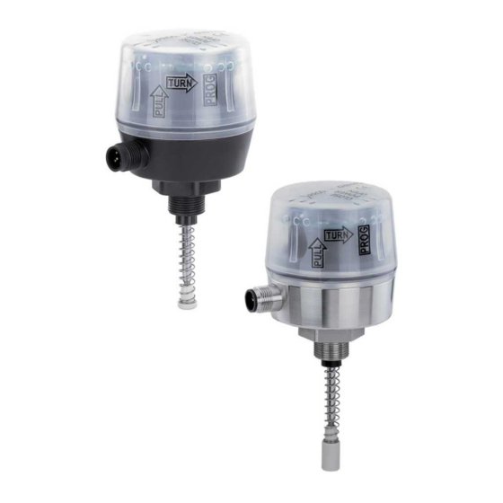
3.3 Beschreibung Die Stellungsrückmelder GEMÜ 1235 / 1236 sind für die Montage auf pneumatisch betätigte Antriebe geeignet. Die Position der Ventilspindel wird durch die spielfreie und kraftschlüssige Adaption zuverlässig elektronisch erfasst und ausgewertet. Intelligen- te mikroprozessorgesteuerte Funktionen erleichtern die Inbetriebnahme und unterstützen im Betrieb. Die aktuelle Stellung des Ventils wird über Weitsicht-LEDs angezeigt und über elektrische Signale zurückgemeldet. -
Page 9: Funktion
3 Produktbeschreibung 3.4 Funktion Der Stellungsrückmelder GEMÜ 1235 / 1236 signalisiert die Stellung des Ventils. Wird das Ventil geöffnet, bewegt sich die Spin- del des Stellungsrückmelders nach oben und signalisiert über die Weitsicht-LEDs und die Kommunikationsschnittstelle die Ven- tilposition AUF. Wird das Ventil geschlossen, drückt die Feder des Anbausatzes die Spindel des Stellungsrückmelders nach un- ten und signalisiert über die Weitsicht-LEDs und die Kommunikationsschnittstelle die Ventilposition ZU. -
Page 10: Gemü Conexo
(Potentiometer). Dieses wird kraftschlüssig mit Hilfe eines Anbausatzes (Feder, Betätigungsspindel) mit der Spin- del des Antriebes verbunden. Über die elektrischen Anschlüsse können die Ventilendlagen und der integrierte Weggeber über- wacht werden. ● Das Produkt gemäß den technischen Daten einsetzen. GEMÜ 1235 / 1236 10 / 56 www.gemu-group.com 24V, 3S, 4S... -
Page 11: Bestelldaten
Weitsichtstellungsanzeige, IO-Link Kommunikation 5 Elektrischer Anschluss M125 M12 Stecker, 5-polig 6 Weggeberausführung Potentiometer 30 mm Länge 7 Gehäusewerkstoff Unterteil 1.4301, Oberteil PP, M16 Gewinde, 1.4305 8 Sonderausführung UL-Zulassung www.gemu-group.com 11 / 56 GEMÜ 1235 / 1236 24V, 3S, 4S... -
Page 12: Technische Daten
Störfestigkeit: DIN EN 61000-6-2 (Nov. 2019) Störaussendung: DIN EN 61000-6-3 SIL: Produktbeschreibung: Elektrischer Stellungsrückmelder GEMÜ 1235 / 1236 Gerätetyp: Gültige Software-Version: V 1.0.0.4 Sicherheitsfunktion: Die Sicherheitsfunktion wird definiert als High (24 V DC) Signal an Pin 5 (Geräteausführung 3S/4S) und an Pin 4 (Geräteausführung 3E/4E), wenn die aktuelle Position... - Page 13 Schaltpunkt AUF 0,5 mm 0,9 mm 1,25 mm Sind die prozentualen Schaltpunkte in Abhängigkeit vom programmierten Hub kleiner als die zuläs- sigen min. Schaltpunkte gelten automatisch die min. Schaltpunkte. www.gemu-group.com 13 / 56 GEMÜ 1235 / 1236 24V, 3S, 4S...
-
Page 14: Abmessungen
ø 60 TURN SW 27 Weggeberausführung Code 65,5 87,5 112,5 30,5 55,5 19,0 41,0 66,0 Maße in mm 8.2 Befestigungsbügel 1235/1236 PTAZ für direkten Anbau an Schwenkantriebe Ø37 Wellenhöhe Lochabstand 20,0 80,0 40,0 100,0 30,0 80,0 50,0 100,0 50,0 130,0... -
Page 15: Herstellerangaben
2. UV-Strahlung und direkte Sonneneinstrahlung vermeiden. 3. Maximale Lagertemperatur nicht überschreiten (siehe Kapitel „Technische Daten“). 4. Lösungsmittel, Chemikalien, Säuren, Kraftstoffe u. ä. nicht mit GEMÜ Produkten und deren Ersatzteilen in einem Raum la- gern. www.gemu-group.com 15 / 56 GEMÜ 1235 / 1236 24V, 3S, 4S... -
Page 16: Montage Und Installation
2. Optische Stellungsanzeige 2 und / oder Abdeckkappe 1 vom Antriebsoberteil entfernen. 10.2 Montagevorbereitung des Ventils (Schwenkantrieb) 1. Antrieb A in Grundstellung (Antrieb entlüftet) bringen. 2. Schraube 1 von Puck 2 demontieren. GEMÜ 1235 / 1236 16 / 56 www.gemu-group.com 24V, 3S, 4S... -
Page 17: Montage Anbausatz An Stellungsrückmelder
ð Hierzu die seitlichen Schrauben 5 lösen und die Haltefüße auf die Gewinde des Antriebs setzen und mit Schrauben 4 montieren. 2. Bügel 3 wie abgebildet an den Haltefüßen fixieren, dabei muss die Abgriffswelle spielfrei in der Welle des Antriebs sitzen. www.gemu-group.com 17 / 56 GEMÜ 1235 / 1236 24V, 3S, 4S... -
Page 18: Montage Hubbegrenzung (Linearantrieb)
Abdeckkappe Dichtung Stellungsanzeige Scheibe Betätigungsspindel Distanzstück Spindel Antriebsspindel Weggeber 1) nur bei Ventilen mit Steuerfunktion NO und DA verfügbar. 2) nur bei erforderlichen Anbausätzen beiliegend. Die Ausführung ist ventilabhängig. GEMÜ 1235 / 1236 18 / 56 www.gemu-group.com 24V, 3S, 4S... -
Page 19: Montage Stellungsrückmelder (Linearantrieb)
5. Das Produkt initialisieren. 6. Das Produkt mit Anbausatz ist komplett montiert. 7. Das Produkt mit Anbausatz und Adapter ist komplett montiert. 8. Das Produkt mit Anbausatz und Hubbegrenzung ist komplett montiert. www.gemu-group.com 19 / 56 GEMÜ 1235 / 1236 24V, 3S, 4S... -
Page 20: Montage Stellungsrückmelder (Schwenkantrieb)
11 Elektrischer Anschluss 11.1 24 V, Bestelloption Geräteausführung, Code 3S/4S/3X/4X Beschreibung U, 24 V DC, Versorgungsspannung U, GND 24 V DC, Ausgang Endlage Auf n.c. 24 V DC, Ausgang Endlage Zu GEMÜ 1235 / 1236 20 / 56 www.gemu-group.com 24V, 3S, 4S... -
Page 21: Programmierung Der Endlagen
TURN 4. Ventil auffahren bis Endlage erreicht ist. 5. Ventil zufahren bis Endlage erreicht ist. 6. Gehäuseoberteil im Uhrzeigersinn zurück drehen und nach unten drücken. ð Endlagen sind eingestellt. www.gemu-group.com 21 / 56 GEMÜ 1235 / 1236 24V, 3S, 4S... -
Page 22: Fehlerbehebung
OPEN und CLOSED blinken alternierend Sensorfehler Position AUF Position ZU Kurzschluss Ausgang AUF Signalausgang Ausgang ZU AUF+ZU Interner Fehler OPEN und CLOSED blinken simultan Versorgungsspannung zu niedrig leuchtet nicht relevant blinkt GEMÜ 1235 / 1236 22 / 56 www.gemu-group.com 24V, 3S, 4S... - Page 23 Überprüfung der Verkabelung und Gerä- teausführung Kommunikationsfehler Kommunikation gestört oder abgebro- Überprüfung der Verkabelung chen Versorgungsspannung zu niedrig Versorgungsspannung zu niedrig Versorgungsspannung gemäß Kapitel „Technische Daten“ gewährleisten Interner Fehler Speicherfehler Gerät einschicken www.gemu-group.com 23 / 56 GEMÜ 1235 / 1236 24V, 3S, 4S...
-
Page 24: Inspektion Und Wartung
Reparatur, sondern eine kostenpflichtige Entsorgung. 1. Das Produkt reinigen. 2. Rücksendeerklärung bei GEMÜ anfordern. 3. Rücksendeerklärung vollständig ausfüllen. 4. Das Produkt mit ausgefüllter Rücksendeerklärung an GEMÜ schicken. GEMÜ 1235 / 1236 24 / 56 www.gemu-group.com 24V, 3S, 4S... -
Page 25: Original Eu-Einbauerklärung Im Sinne Der Eg-Maschinenrichtlinie 2006/42/Eg, Anhang Ii B
Verantwortung, dass das nachfolgend bezeichnete Produkt den einschlägigen grundlegenden Si- cherheits- und Gesundheitsschutzanforderungen nach Anhang I der oben genannten Richtlinie entspricht. Texte MRL Produkt: GEMÜ 1235 / 1236 Produktname: Elektrischer Stellungsrückmelder Folgende grundlegenden Sicherheits- 1.1.2.; 1.1.3.; 1.1.5.; 1.3.2.; 1.3.4.; 1.3.7.; 1.5.1.; 1.5.5.; 1.6.1.; 1.6.3.; 1.6.4.; 1.7.1.;... -
Page 26: Original Eu-Konformitätserklärung Gemäß 2014/30/Eu (Emv-Richtlinie)
D-74653 Ingelfingen-Criesbach erklären hiermit in alleiniger Verantwortung, dass das nachfolgend bezeichnete Produkt den Vorschriften der oben genannten Richtlinie entspricht. Texte EMV Produkt: GEMÜ 1235 / 1236 Produktname: Elektrischer Stellungsrückmelder Folgende harmonisierte Normen (oder EN 61326-1:2013; EN 61000-6-2:2005/AC:2005 Teile hieraus) wurden angewandt: ______________________________________________ i.V. -
Page 27: Original Eu-Konformitätserklärung Gemäß 2011/65/Eu (Rohs-Richtlinie)
D-74653 Ingelfingen-Criesbach erklären hiermit in alleiniger Verantwortung, dass das nachfolgend bezeichnete Produkt den Vorschriften der oben genannten Richtlinie entspricht. Texte EMV Produkt: GEMÜ 1235 / 1236 Produktname: Elektrischer Stellungsrückmelder Folgende harmonisierte Normen (oder EN IEC 63000:2018 Teile hieraus) wurden angewandt: ______________________________________________ i.V. -
Page 28: Ul Zertifikat
PROCESS CONTROL EQUIPMENT, ELECTRICAL This certificate confirms that representative samples of Open Type Electro-Pneumatic Positioner/Controller models: 1235, 1236, and 1436 Eco Have been investigated by UL in accordance with the Standard(s) indicated on this Certificate. UL 61010-1 Safety Requirements For Electrical Equipment... - Page 29 5 Correct use ............6 Order data ............7 Technical data ............. 8 Dimensions ............1235/1236 electrical position indicator ..1235/1236 PTAZ mounting bracket for dir- ect mounting on quarter turn actuators ..9 Manufacturer's information ........Delivery ............Packaging ............
-
Page 30: General Information
The following signal words and danger levels are used: DANGER Imminent danger! ▶ Non-observance can cause death or severe injury. WARNING Potentially dangerous situation! ▶ Non-observance can cause death or severe injury. GEMÜ 1235 / 1236 30 / 56 www.gemu-group.com 24V, 3S, 4S... - Page 31 Potentially dangerous situation! ▶ Non-observance can cause damage to property. The following symbols for the specific dangers can be used within a warning note: Symbol Meaning Danger of explosion! www.gemu-group.com 31 / 56 GEMÜ 1235 / 1236 24V, 3S, 4S...
-
Page 32: Safety Information
14. Do not carry out any maintenance work and repairs not described in this document without consulting the manufacturer first. In cases of uncertainty: 15. Consult the nearest GEMÜ sales office. GEMÜ 1235 / 1236 32 / 56 www.gemu-group.com 24V, 3S, 4S... -
Page 33: Product Description
GEMÜ 1236 Item Name Materials Housing cover Housing base GEMÜ 1235: PVDF GEMÜ 1236: SS Electrical connection PVDF Adapter piece PVDF Mounting kit, valve-specific Valve-specific materials Seals EPDM, PUR www.gemu-group.com 33 / 56 GEMÜ 1235 / 1236 24V, 3S, 4S... -
Page 34: Status Leds
3.2.1 LED conditions Function – Device version 3S / 4S CLOSED ERROR OPEN Valve in OPEN position Valve in CLOSED position Programming mode LED conditions lit (on) irrelevant flashes GEMÜ 1235 / 1236 34 / 56 www.gemu-group.com 24V, 3S, 4S... -
Page 35: Description
3 Product description 3.3 Description GEMÜ 1235 / 1236 electrical position indicators are suitable for mounting on pneumatically operated actuators. The position of the valve spindle is reliably electronically detected and evaluated using play-free and non-positive mounting. Intelligent micro- processor controlled functions facilitate commissioning and support during operation. The current position of the valve is dis- played via high-visibility LEDs and fed back via electrical signals. -
Page 36: Gemü Conexo
(spring, operating bush). The valve end positions and the integrated travel sensor can be controlled via the electrical connections. ● Use the product in accordance with the technical data. GEMÜ 1235 / 1236 36 / 56 www.gemu-group.com... -
Page 37: Order Data
5 Electrical connection M125 M12 plug, 5-pin 6 Travel sensor version Potentiometer, 30 mm length 7 Housing material Base 1.4301, PP cover, M16 thread, 1.4305 8 Special version UL approval www.gemu-group.com 37 / 56 GEMÜ 1235 / 1236 24V, 3S, 4S... -
Page 38: Technical Data
30.0 mm 50.0 mm 75.0 mm Hysteresis: 0.2 mm 0.4 mm 0.5 mm Accuracy: 0.2% Full Scale 7.4 Operating conditions Ambient conditions: Use in indoor spaces (only relevant for UL) GEMÜ 1235 / 1236 38 / 56 www.gemu-group.com 24V, 3S, 4S... - Page 39 0.9 mm 1.25 mm If the percentage switch points dependent on the programmed stroke are smaller than the permiss- ible min. switch points, the min. switch points apply automatically. www.gemu-group.com 39 / 56 GEMÜ 1235 / 1236 24V, 3S, 4S...
-
Page 40: Dimensions
SW 27 Travel sensor version code 65.5 87.5 112.5 30.5 55.5 19.0 41.0 66.0 Dimensions in mm 8.2 1235/1236 PTAZ mounting bracket for direct mounting on quarter turn actuators Ø37 Shaft height Hole spacing 20.0 80.0 40.0 100.0 30.0 80.0 50.0 100.0... -
Page 41: Manufacturer's Information
3. Do not exceed the maximum storage temperature (see chapter "Technical data"). 4. Do not store solvents, chemicals, acids, fuels or similar fluids in the same room as GEMÜ products and their spare parts. www.gemu-group.com 41 / 56 GEMÜ 1235 / 1236 24V, 3S, 4S... -
Page 42: Assembly And Installation
10.2 Preparations for assembly to the valve (quarter turn actuator) 1. Move the actuator A into zero position (actuator vented). 2. Remove the screw 1 from the trigger cam 2. GEMÜ 1235 / 1236 42 / 56 www.gemu-group.com 24V, 3S, 4S... -
Page 43: Mounting Kit Assembly On Electrical Position Indicator
2. Secure the bracket 3 to the retaining feet as shown. In doing so, the tap shaft must sit free of play in the shaft of the actu- ator. www.gemu-group.com 43 / 56 GEMÜ 1235 / 1236 24V, 3S, 4S... -
Page 44: Assembling The Stroke Limiter (Linear Actuator)
Actuator spindle Travel sensor 1) Only available for valves with the NO and DA control functions. 2) Only included in required mounting kits. The design depends on the valve. GEMÜ 1235 / 1236 44 / 56 www.gemu-group.com 24V, 3S, 4S... -
Page 45: Installing The Electrical Position Indicator (Linear Actuator)
6. The product with mounting kit is fully assembled. 7. The product with mounting kit and adapter is fully assembled. 8. The product with mounting kit and stroke limiter is fully assembled. www.gemu-group.com 45 / 56 GEMÜ 1235 / 1236 24V, 3S, 4S... -
Page 46: Installing The Electrical Position Indicator (Quarter Turn Actuator)
11.1 24 V, ordering option device version, code 3S/4S/3X/4X Description U, 24 V DC, supply voltage U, GND 24 V DC, Open end position output n. c. 24 V DC, Closed end position output GEMÜ 1235 / 1236 46 / 56 www.gemu-group.com 24V, 3S, 4S... -
Page 47: Programming The End Positions
4. Open valve until end position is reached. 5. Close valve until end position is reached. 6. Turn the housing cover back clockwise and press it down. ð The end positions are set. www.gemu-group.com 47 / 56 GEMÜ 1235 / 1236 24V, 3S, 4S... -
Page 48: Troubleshooting
Sensor error OPEN position CLOSED position Short-circuit Output OPEN signal output Output CLOSED OPEN+CLOSED Internal error OPEN and CLOSED flash simultaneously Supply voltage too low lit (on) irrelevant flashes GEMÜ 1235 / 1236 48 / 56 www.gemu-group.com 24V, 3S, 4S... - Page 49 Communication disturbed or interrupted Check the wiring Supply voltage too low Supply voltage too low Ensure supply voltage in accordance with chapter "Technical data" Internal error Memory error Return device www.gemu-group.com 49 / 56 GEMÜ 1235 / 1236 24V, 3S, 4S...
-
Page 50: Inspection And Maintenance
1. Clean the product. 2. Request a return delivery note from GEMÜ. 3. Complete the return delivery note. 4. Send the product with a completed return delivery note to GEMÜ. GEMÜ 1235 / 1236 50 / 56 www.gemu-group.com 24V, 3S, 4S... -
Page 51: Eu Declaration Of Incorporation According To The Ec Machinery Directive 2006/42/Ec, Annex Ii B
Machinery Directive 2006/42/EC. M. Barghoorn Head of Global Technics Ingelfingen, 21/08/2023 GEMÜ Gebr. Müller Apparatebau GmbH & Co. KG www.gemu-group.com Fritz-Müller-Straße 6-8 D-74653 Ingelfingen-Criesbach info@gemue.de www.gemu-group.com 51 / 56 GEMÜ 1235 / 1236 24V, 3S, 4S... -
Page 52: Eu Declaration Of Conformity In Accordance With 2014/30/Eu (Emc Directive)
EN 61326-1:2013; EN 61000-6-2:2005/AC:2005 parts thereof) have been applied: M. Barghoorn Head of Global Technics Ingelfingen, 21/08/2023 GEMÜ Gebr. Müller Apparatebau GmbH & Co. KG www.gemu-group.com Fritz-Müller-Straße 6-8 D-74653 Ingelfingen-Criesbach info@gemue.de GEMÜ 1235 / 1236 52 / 56 www.gemu-group.com 24V, 3S, 4S... - Page 53 EN IEC 63000:2018 parts thereof) have been applied: M. Barghoorn Head of Global Technics Ingelfingen, 21/08/2023 GEMÜ Gebr. Müller Apparatebau GmbH & Co. KG www.gemu-group.com Fritz-Müller-Straße 6-8 D-74653 Ingelfingen-Criesbach info@gemue.de www.gemu-group.com 53 / 56 GEMÜ 1235 / 1236 24V, 3S, 4S...
- Page 54 PROCESS CONTROL EQUIPMENT, ELECTRICAL This certificate confirms that representative samples of Open Type Electro-Pneumatic Positioner/Controller models: 1235, 1236, and 1436 Eco Have been investigated by UL in accordance with the Standard(s) indicated on this Certificate. UL 61010-1 Safety Requirements For Electrical Equipment...
- Page 55 21 UL certificate www.gemu-group.com 55 / 56 GEMÜ 1235 / 1236 24V, 3S, 4S...
- Page 56 GEMÜ Gebr. Müller Apparatebau GmbH & Co. KG Fritz-Müller-Straße 6-8, 74653 Ingelfingen-Criesbach, Germany Änderungen vorbehalten Phone +49 (0) 7940 1230 · info@gemue.de Subject to alteration www.gemu-group.com 09.2023 | 88885704...
Need help?
Do you have a question about the 1235 and is the answer not in the manual?
Questions and answers